AccidentalRebel
-
Tell Time Contest
12/11/2019 at 00:37 • 0 commentsI just recently learned about the Tell Time Contest here on Hackaday and immediately thought that TIRO is a good fit for it.
I feel that my project is unique enough and has a function that can easily tell time (Although without a display). These tick two out of the three judging criterias. What's lacking is in the craftsmanship department.
I might re-build TIRO and add some improvements to it, like having an external crystal for accurate timing. I will also need to ditch protoboards and have a proper one printed. And for the case, maybe a 3D printed case?
I'm not fully committed to joining yet as I do have a lot of other projects that are pending. Updating TIRO has been in my backlog for quite awhile though and this might be the perfect time to revive it.
We'll see.
-
Current state and next steps
04/07/2019 at 00:01 • 0 commentsI've been wearing the watch constantly for two weeks already and it has been working great. Thanks to the slider switch that I added the battery life has been extended even more.
The only thing that I want to improve with this build is how it looks. The case is too bulky and, i admit, not that good looking that my wife is always unsure whenever I try to wear it in public. This of course, defeats the purpose of my design. So the next obvious step is to go smaller. And this can be done by using SMD components.
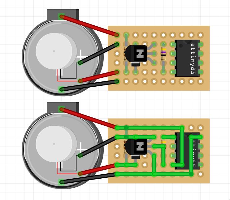
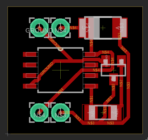
I've already designed a circuit in Eagle which has been a fun experience.
![]() ---------- more ----------
---------- more ----------The only thing keeping me from continuing with this is delivery costs of the printed PCB and the parts. I can go with the cheapest delivery options but I'm afraid it'll get lost in transit, or worse, in our country's customs.
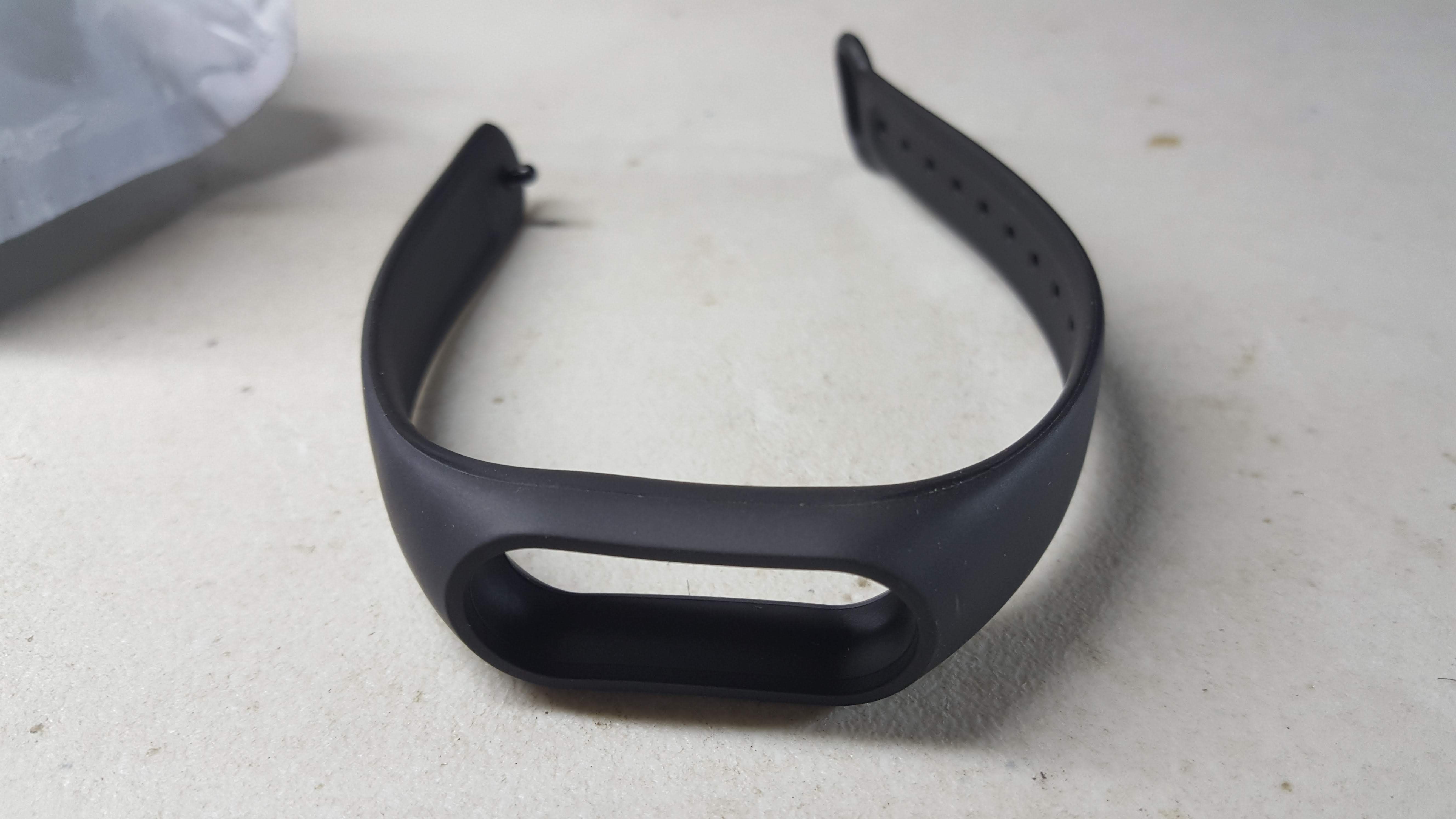
Another option that I'm leaning towards right now is to re-layout the circuit and making it more compact as possible. For me to know what new layout I should aim for, I bought a watch band that looks better looking but also has limited space.
![]()
Here are some not-so-well-thought-out ideas that might help make this possible:
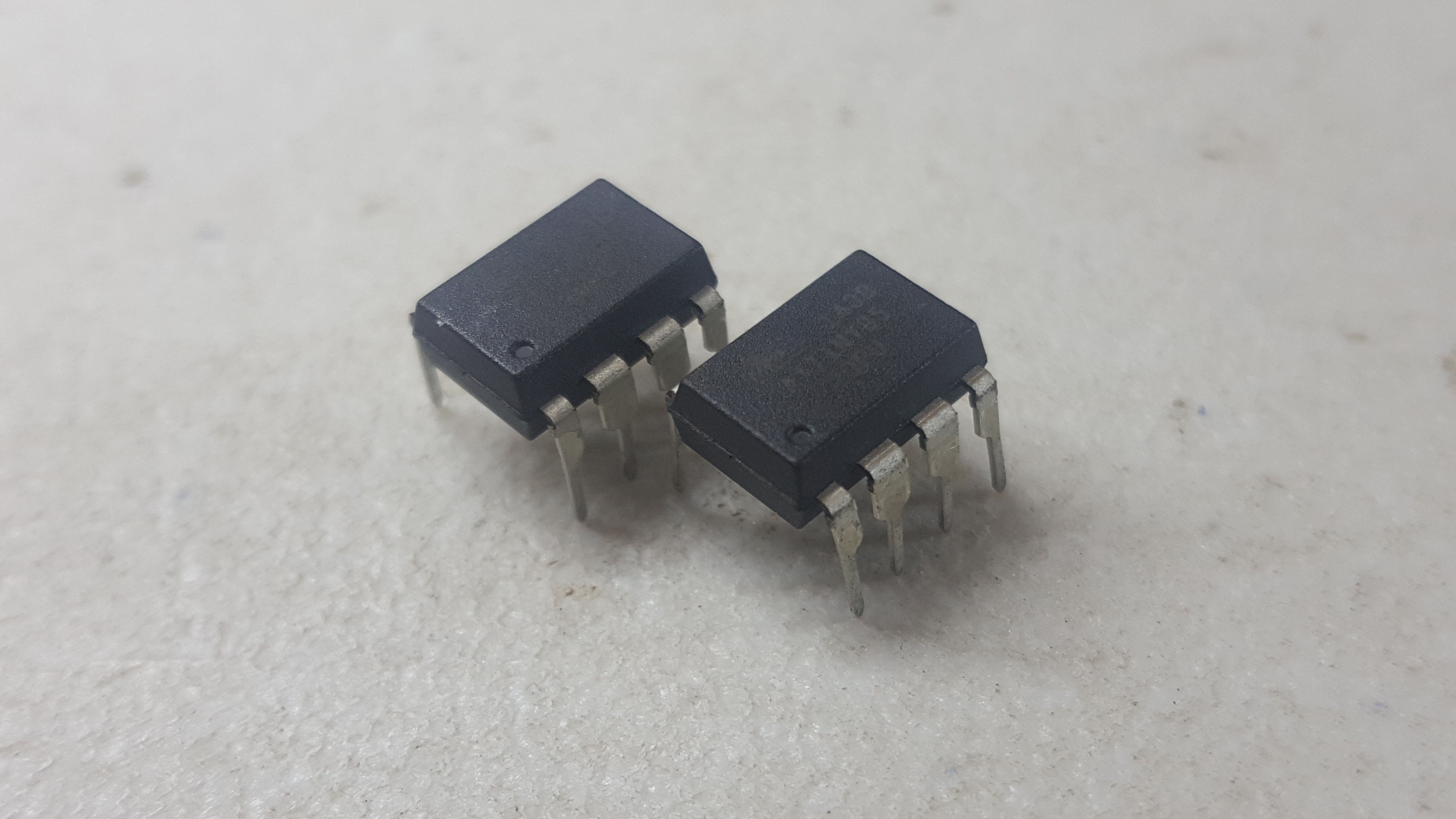
- Don't use an IC socket as it is too bulky. This would mean I'd have to solder the ATTiny85 directly, which I'm fine with as I am pretty happy with the program and have no need to change it.
- Consider removing the R1 resistor connecting to the transistor. I've had tests before where it still worked without it. I just need to make sure it won't fry anything.
- Solder the legs directly of the diode directly to the components. It'll save board space and would allow us to move it to someplace else where there is free space.
- Use thinner and more flexible wires so I can stuff them inside without worrying about them.
- Use a smaller battery than the CR2032. It'll mean less capacity but I can hook up 2-3 small ones in parallel to extend it.
It's a long shot but I think it's doable. I'll think about this some more and will post an update when I'm ready.
-
Created an instructable for this project
03/26/2019 at 06:38 • 0 comments![]()
I've created a how-to guide on how to build the TIRO watch over at Instructables.com.
I had fun making the guide as it allowed me to go through the steps myself and contemplate about my design decisions. It was a lot of work though. It's a good thing that the project is not that complex.
I've mentioned this a couple of times already, but the next step for this project is for me to redesign the circuit by using SMD components. This will result in a smaller watch. This is my first time doing this though so I might take the time to learn and research about it first.
-
Adding a power on-and-off switch
03/19/2019 at 23:38 • 0 commentsAn on-and-off switch is a feature that I didn't have in the design of the initial prototype, but became obvious is needed during testing. This allows users to turn off the watch when not worn to conserve battery life.
Initially my plan was to have the ATTiny85 go to low power sleep when the power down button is pressed and then awaken using an interrupt when pressed again. But I later realized that I don't need something as complicated as this. It's the correct approach if I have an external crystal for timing. For my current design, a simple slide switch in between the battery and the circuit is simpler.
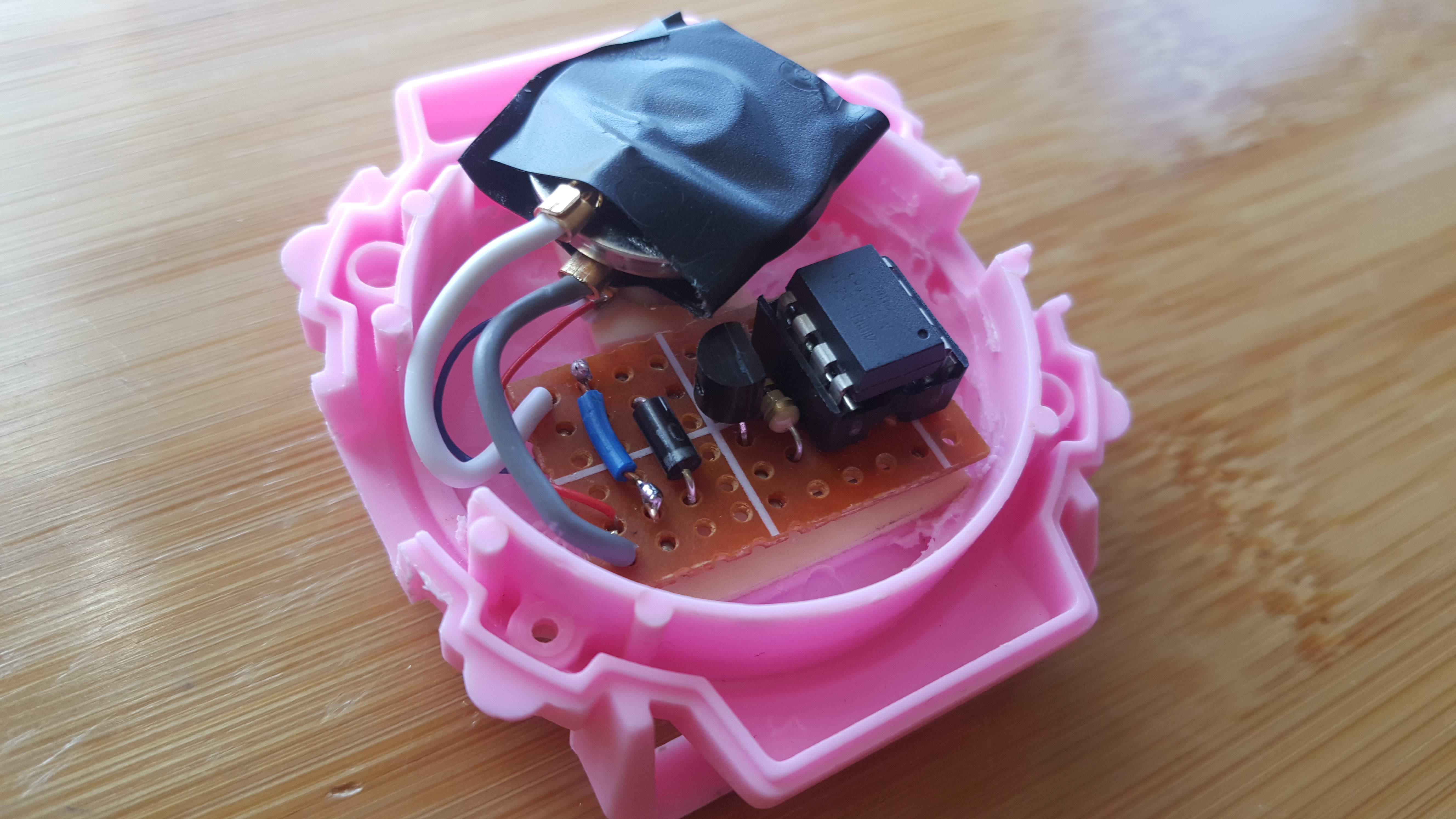
![]()
As you can see there is a slot that allowed me to secure the slider in place. I also had to rotate and move motor which I am not sure is okay as it may have affected how strong the motor is felt.
The next and possibly last step for this version of the prototype is testing how long it would run under normal use. I'll also begin plans for the next prototype iteration which I am excited for. -
Prototype can now be worn
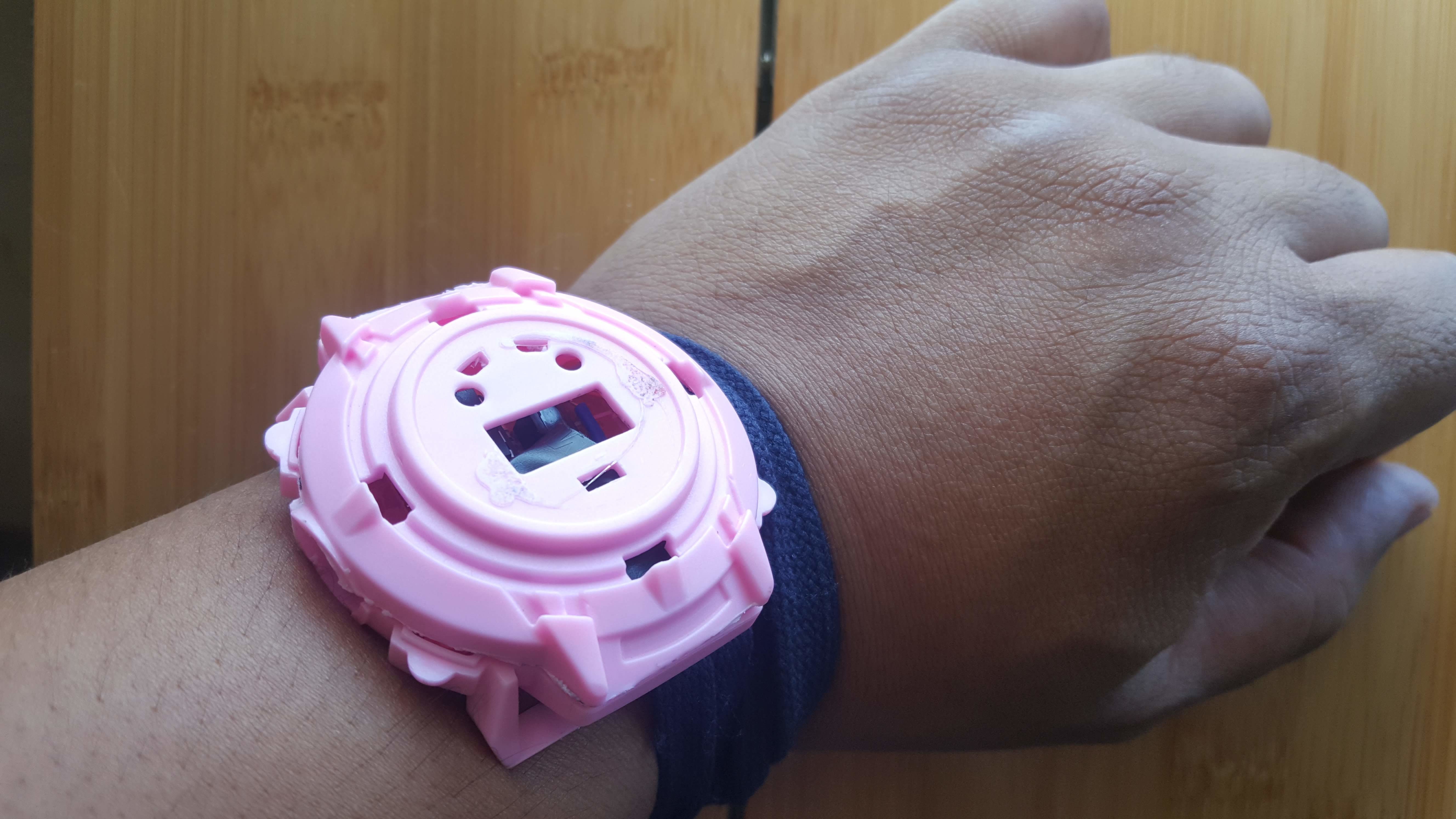
03/18/2019 at 07:34 • 0 commentsThe first prototype for the TIRO Watch (Time is Running Out) can now finally be worn and tested under real world conditions. It looks ugly and too pink right now, but aside from that everything works!
![]()
After wearing the prototype I immediately noticed how weak the vibration of the motor was. This makes sense because the vibration motor now needs to vibrate while attached to the back side of the casing not unlike when it was vibrating freely when it was running on a breadboard.
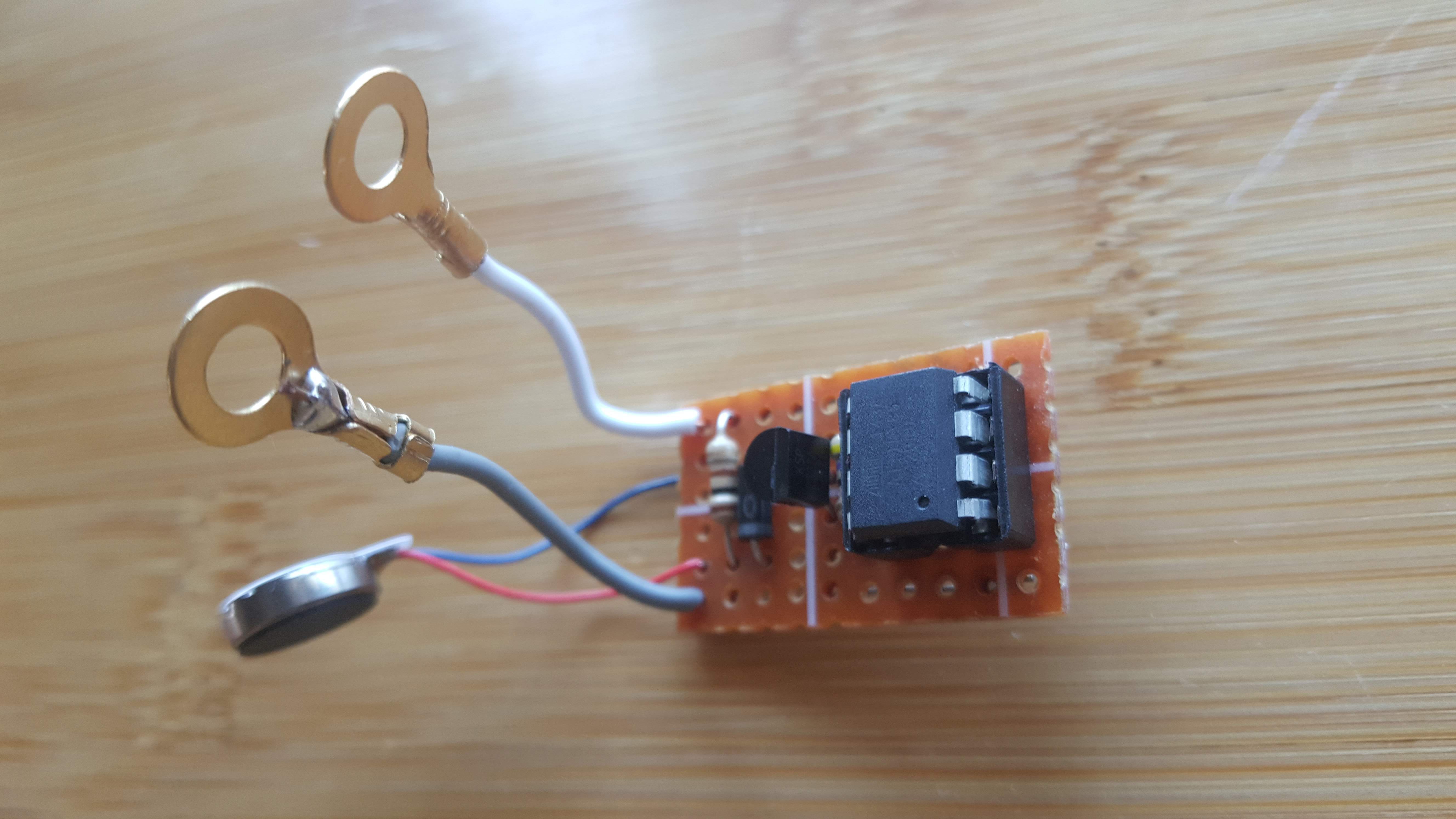
A quick fix I made was that I removed the Resistor 1 in the circuit (At 47 ohms) and placed a wire in it's place (See below image). This made the vibration stronger making it easier to notice. A downside to this change is that the current draw will increase. I have not measured it but based on previous experiments it should be around 20mA more.
![]() ---------- more ----------
---------- more ----------Another thing I did was I tried to come up with a quick hack to hold the CR2032 coin cell battery (Also seen on same image above). I initially went with just bare wires and wrapping the ends with electrical tape but it was not good as the ends tend to get loose easily. I then had this bright idea of using crimp terminal connectors as the contacts and wrapped them with electrical tape. It's better than just the wires but a more cleaner solution would be to wrap with a heatshrink. I currently don't have one available that could fit the battery so this would do for now.
![]()
Also, there currently isn't any way to turn the circuit off to conserve power. This can easily be solved with a simple on and off slider switch in between the battery and the rest of the circuit. It's ugly, but it's the easiest to insert within the circuit without needing to change the whole thing.
So far the prototype is running quite well. I'll be continuing to improve this design until I feel it's ready to be in PCB form.
-
Found a new case
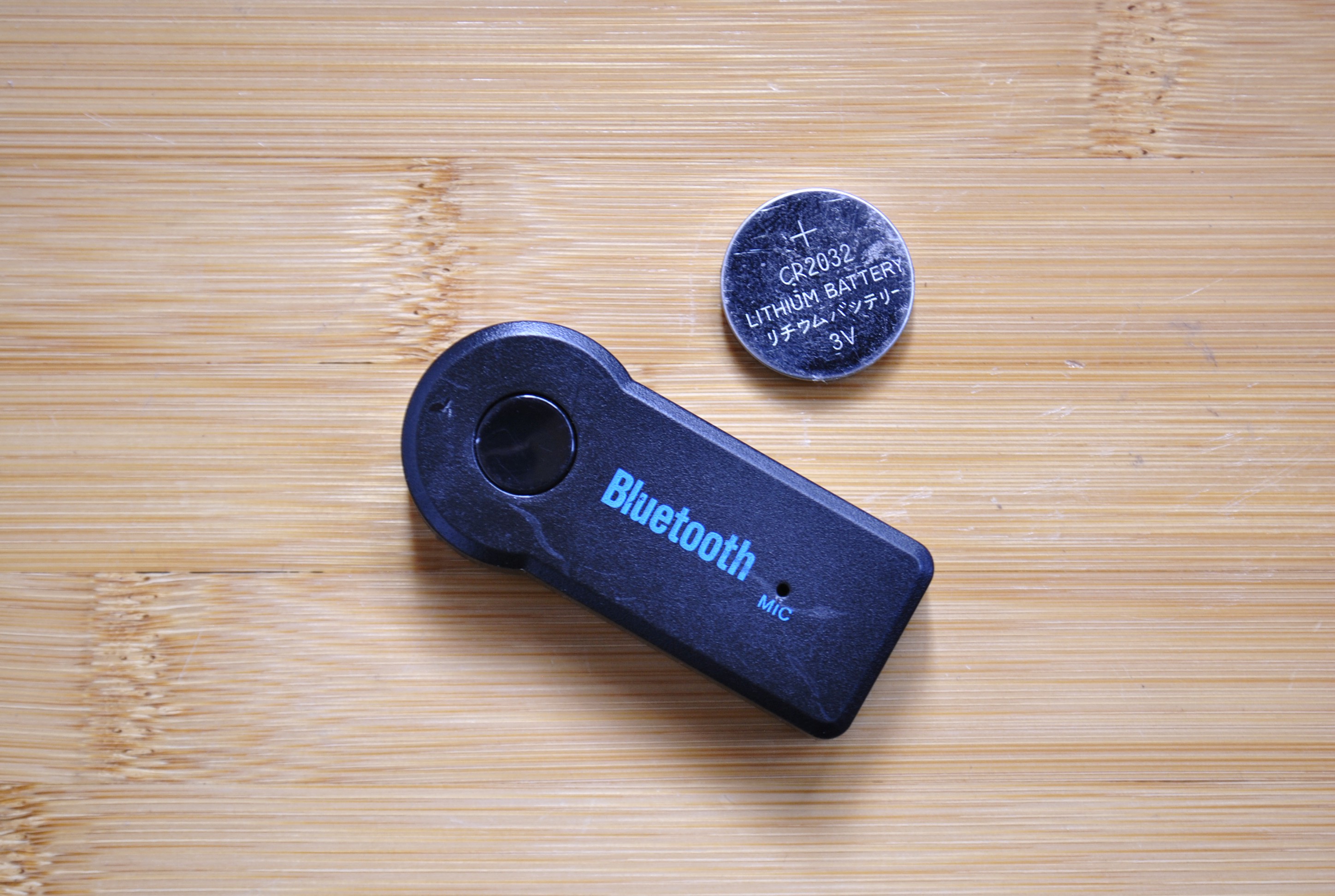
03/15/2019 at 08:37 • 0 commentsInitially I was planning to use the case of a bluetooth dongle as the container for my prototype. Even though I said that aesthetics is not important for now, it did bug me that the case did not look like a watch at all.
I reasoned to myself that in order for me to properly evaluate my prototype, I need to be able to wear it as a watch. To most makers this is an easy problem thanks to 3D printing. Sadly, I don't have one so I have no choice but to use whatever is lying around.
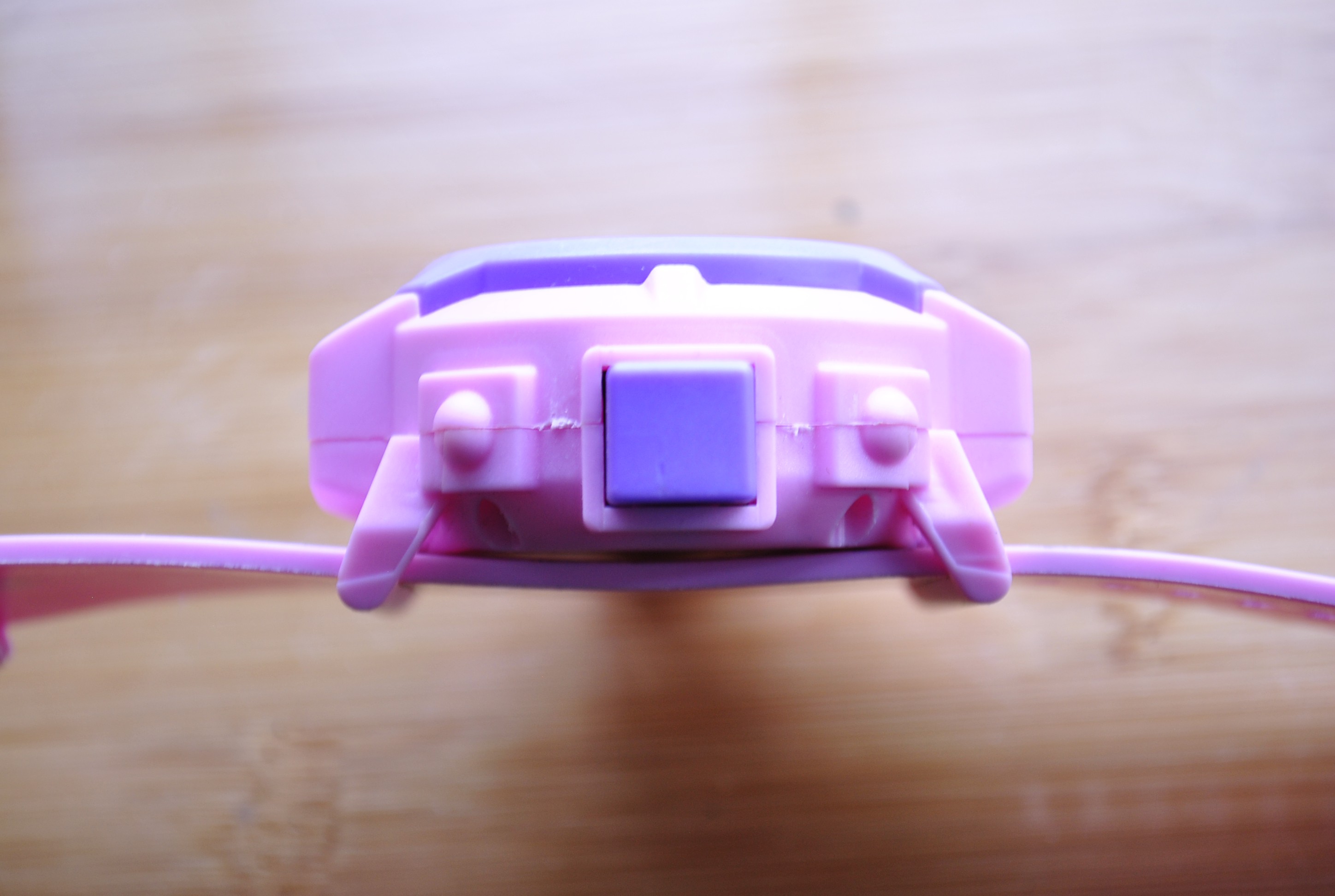
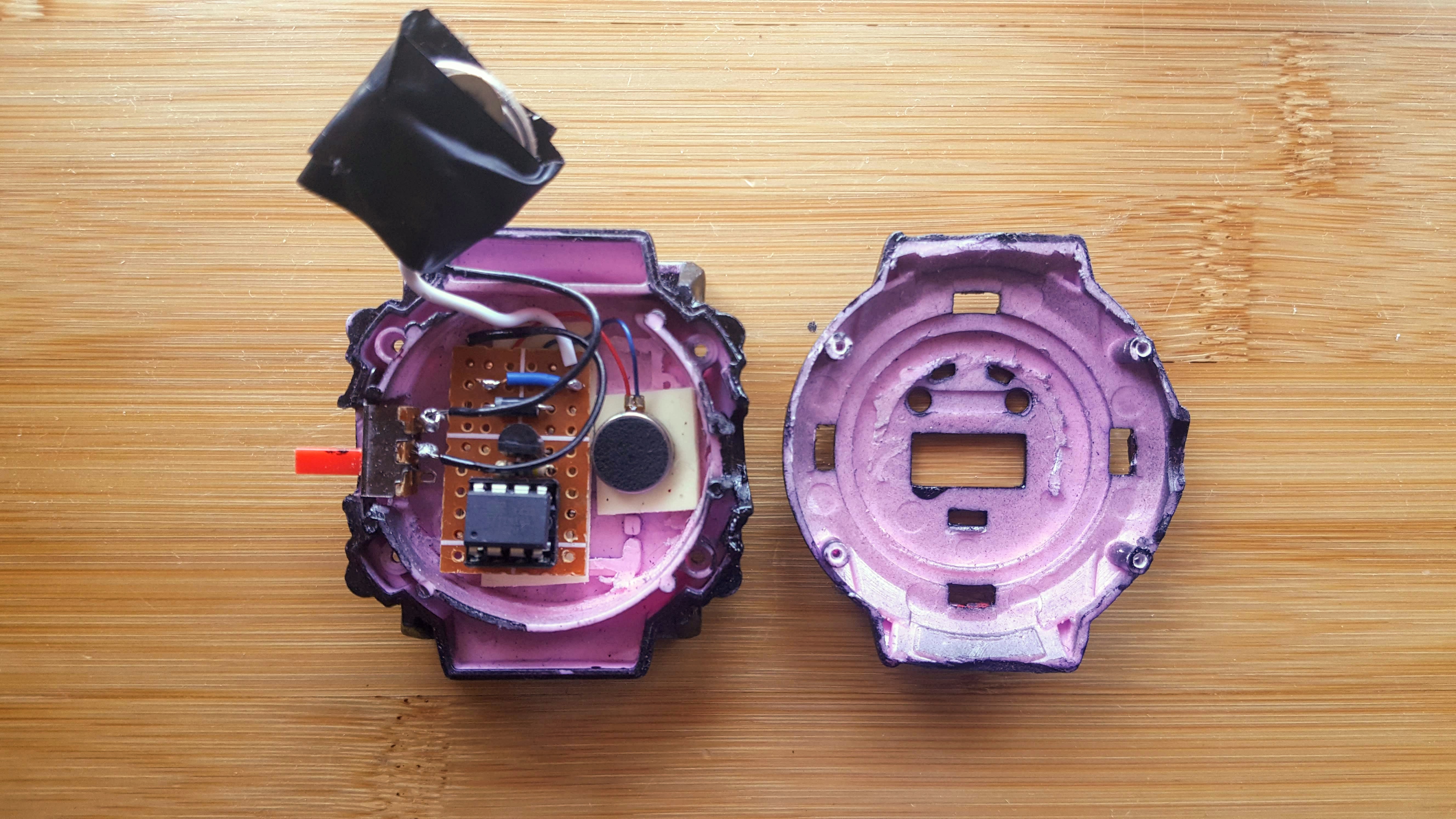
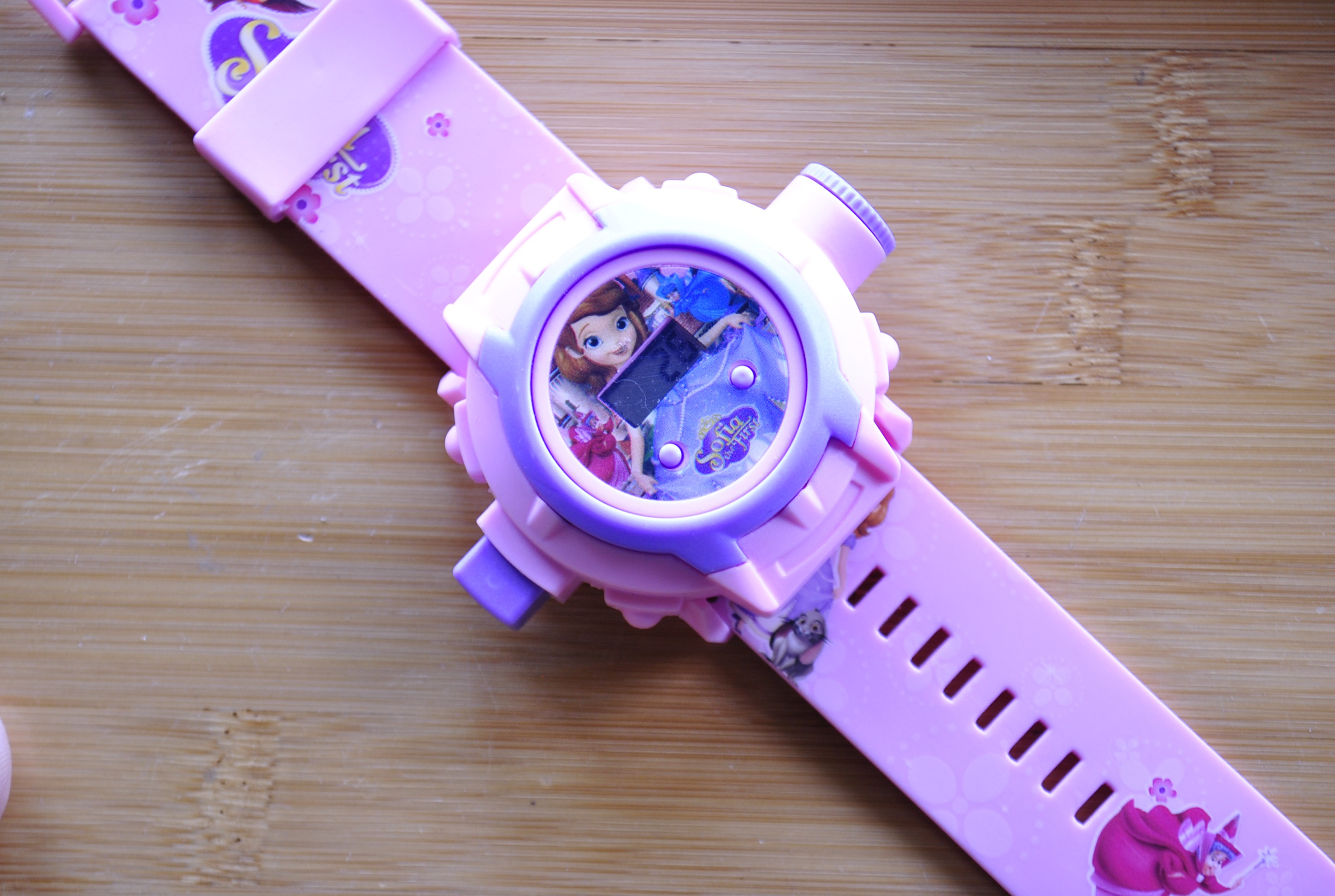
Here's a toy watch that I "borrowed" from my daughter (She's 4, she wouldn't mind).
![]()
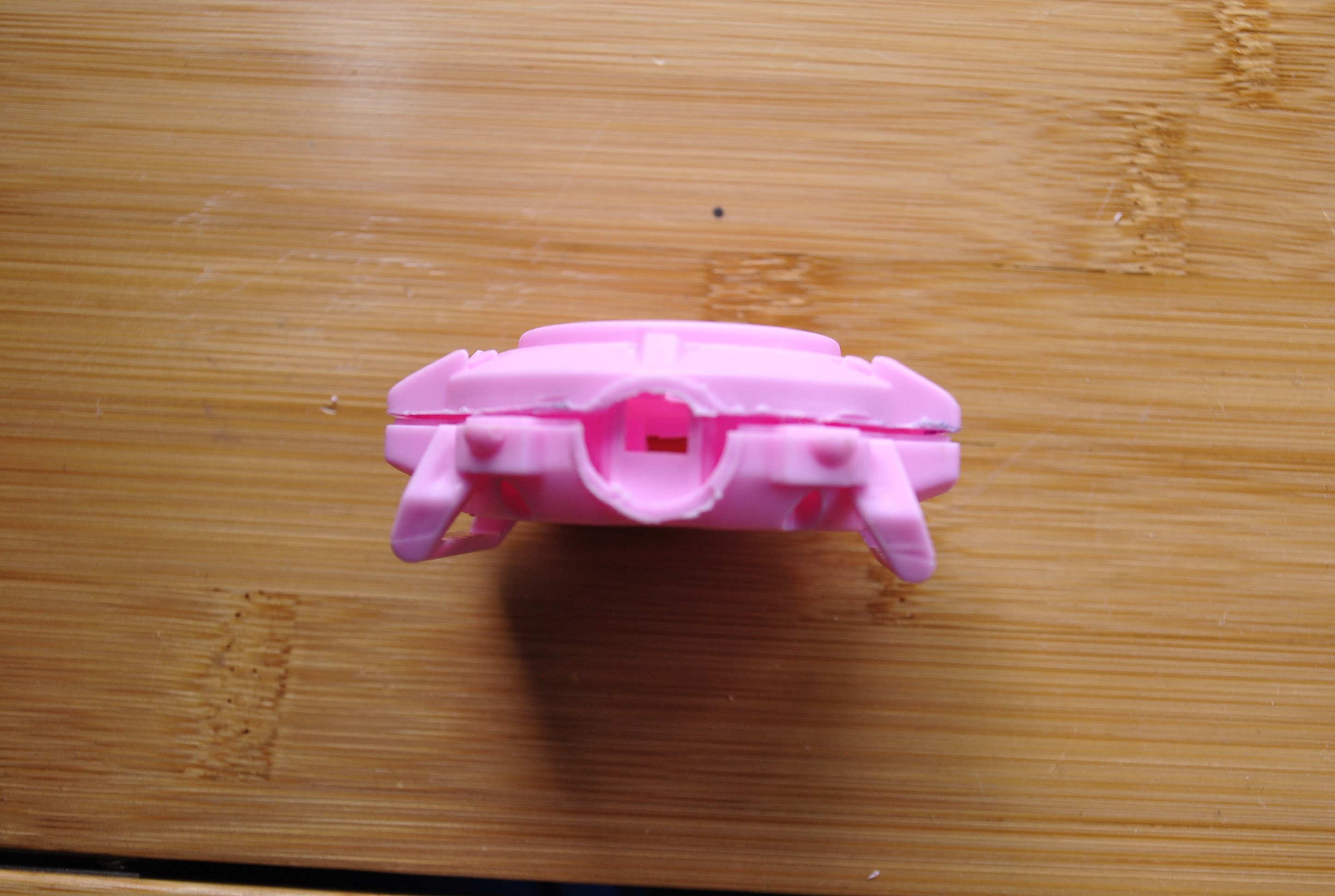
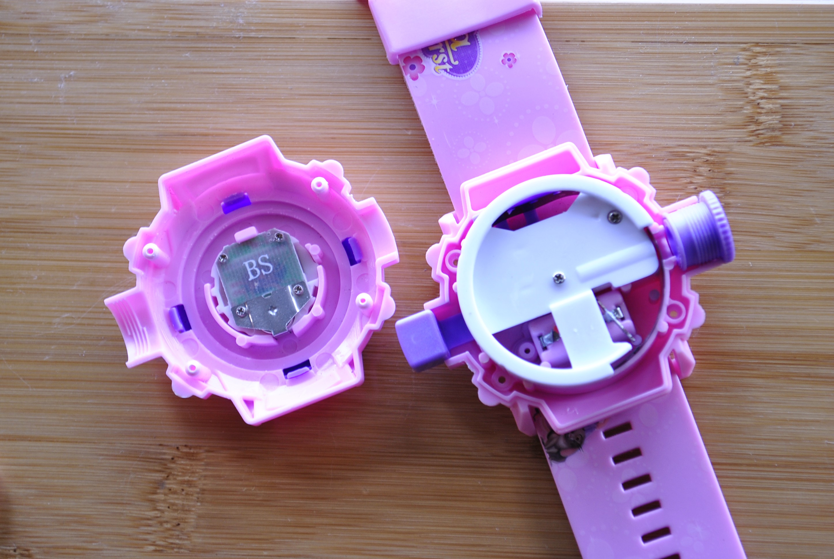
Opening it up shows that there is a lot of room for my project.
![]() There was actually too much room that I cut it so it's not too bulky. So it turned from this:
There was actually too much room that I cut it so it's not too bulky. So it turned from this:![]()
To this:
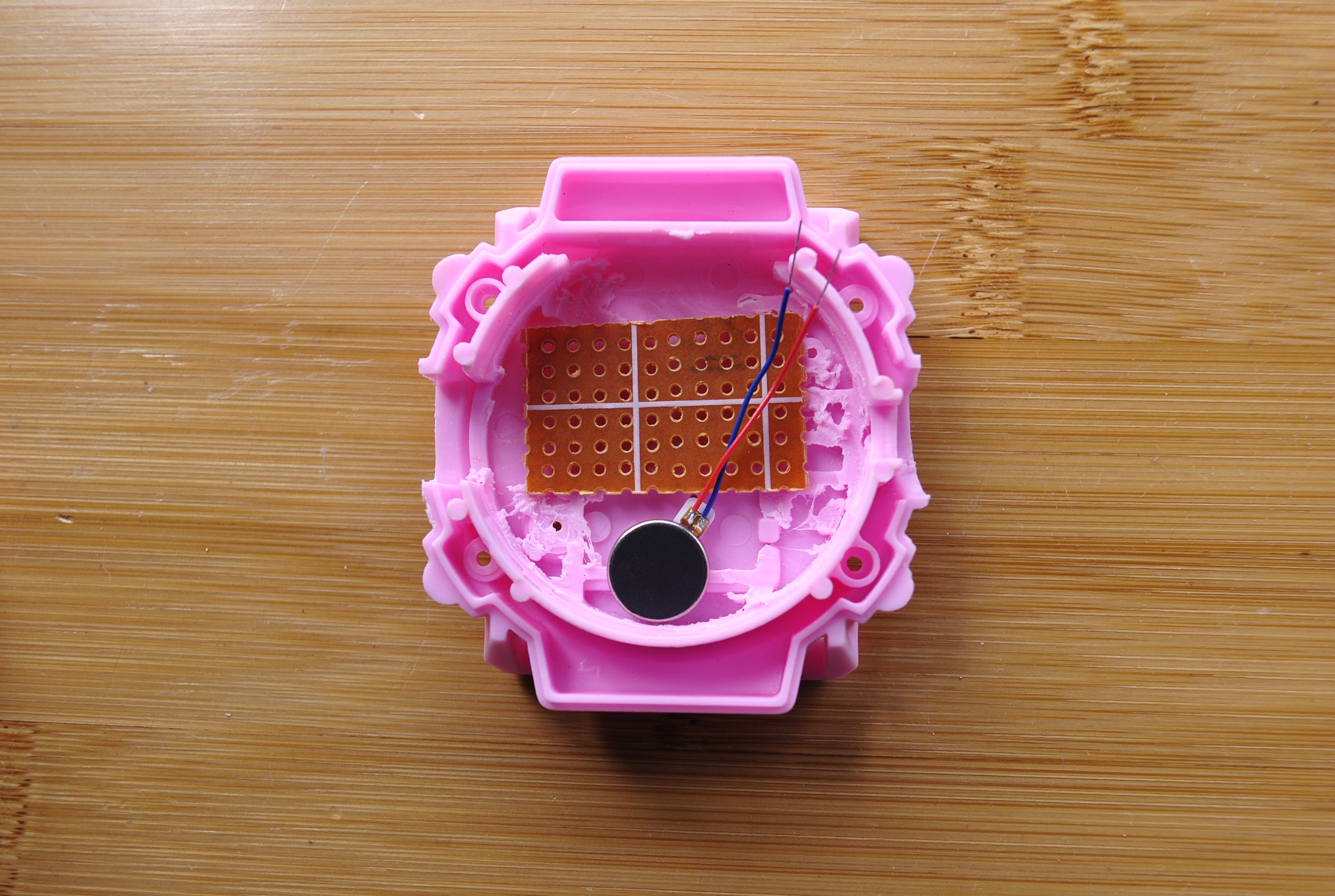
![]() ---------- more ----------
---------- more ----------I'll still be using the circuit diagram I posted before which means we'll still have our 6x10 perfboard which will be hotglued onto the back side of the watch, along with the disc motor.
![]()
The CR2032 battery, on the other hand, I might hotglue to the other side. If there is enough space, I might even add one more battery, and run them in parallel. This will give us a longer lifespan (BTW, lifespan experiments is still ongoing. It's still running 5 days in).
I've ordered a bigger watch band for adults. I'm expecting it to arrive by next week. Hopefully, I'm done soldering this thing together by then.
-
Planning the perfboard layout
03/14/2019 at 08:16 • 0 commentsI am now moving to the next stage of my prototype, which is moving the circuit from the breadboard to perfboard. This means no more new hardware features will be added anymore, at least for this version of the project. I have plans on adding an on-off button and hooking up external clock, but that would be for the next iteration.
Before I could do the move I needed a container first. Sadly, 3D printing a case is out of my reach at the moment, so I have to make do with using the shell of a car Bluetooth device that I have lying around.
![]()
Using this case means that I can't be able to wear it as a watch. I was thinking of drilling holes on the sides and slip a watch band through the case. It would not look good but since it's only a prototype, aesthetics is not my priority at the moment.
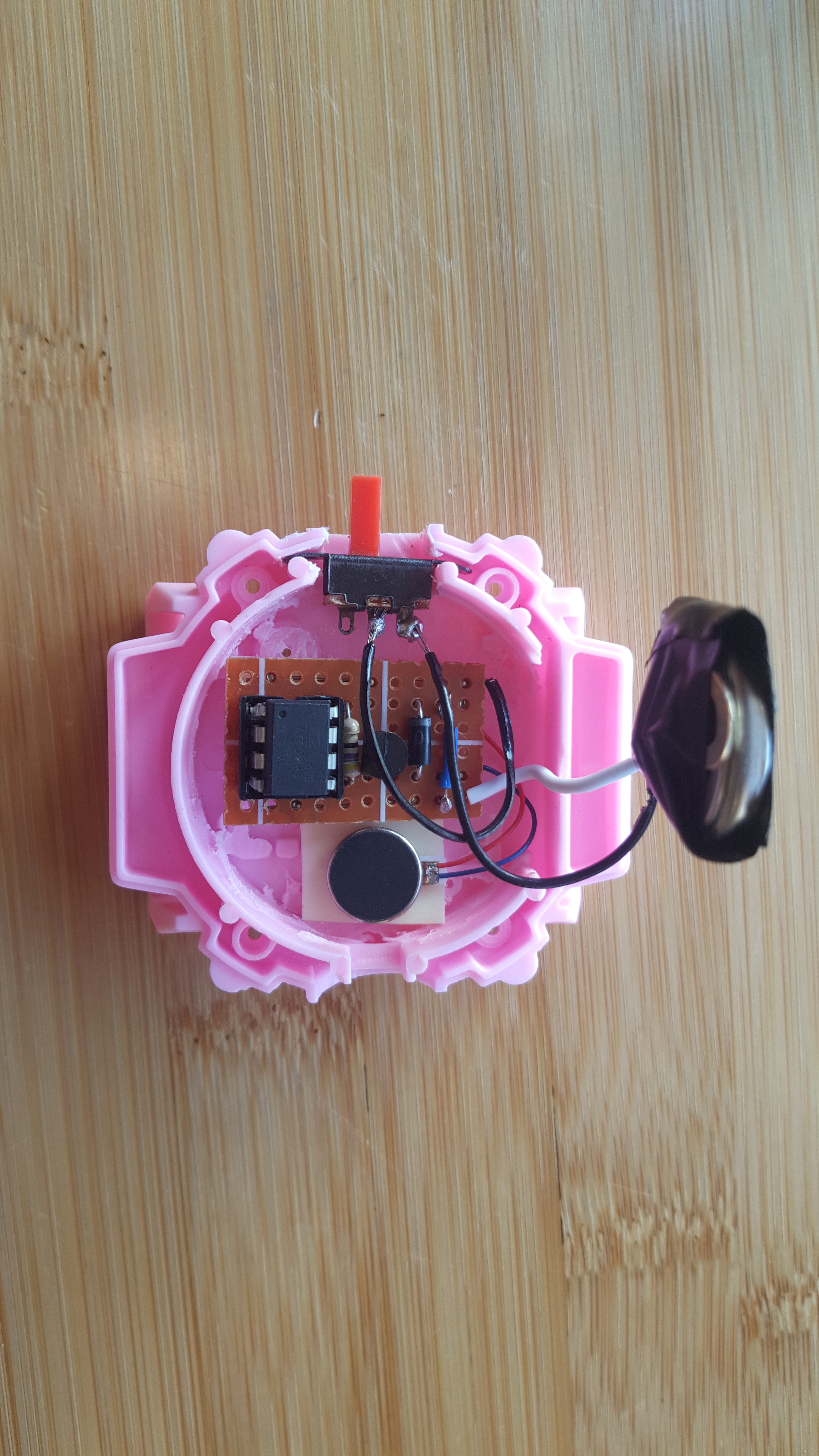
Thankfully, the CR2032 coin cell fits perfectly! I just had to modify the arrangement and placement of the components and ended up with the one below:
![]()
The top image is the top view of the prototype with the components shown, while the bottom image shows the solder connections underneath.
It's a bit tight but I am very happy with the placement. The disc motor I'd have to secure to the casing in some way to make sure that the vibration is more pronounced. Maybe tape it to the top wall, or maybe put it at the bottom of the board? We'll see.
I'll be starting the soldering possibly this weekend.
-
Uploaded code to Github
03/12/2019 at 02:17 • 0 commentsThe results of my recent tests have proven that my code is working and that I can now be confident in sharing it. Here's a link to the repository.
![]()
It has all the basic code that handles running the motor, delays, watchdog timing, and sleeping. It's actually really short but a lot is happening.
If you are interested, you also may want to look into the previous commits. How I started off from the code made by the user Azeria from the Arduino forums, how I then slowly modified it to try out various optimizations, up to the cleaned-up version it is today.
There are still more features to be added to the project (e.g. A button to turn the watch on and off) so the code will definitely be changes to the code in the near future.
-
More than 24 hours uptime. Very promising!
03/09/2019 at 14:07 • 0 comments[Update 2: 72 hours!]
[Update: It's now more than 48 hours!]
More than 24 hours ago I started the test to find out how long my project would run on a CR2032 coin cell battery (More info about the project here). Thankfully, it is still running with still a lot of power left.
![]()
Of course, 24 hours is not a lot, especially for a watch, but it is a big deal because the project that inspired me only run for around 10-11 hours. Plus, my initial pen and paper calculations based on the current drain was around 5-6 hours.
Before this test started I measured the voltage at around 3.17 Volts. Now it's at 2.97 Volts and it seems that the optimizations backed by my research is paying off. I'll continue to run this test until the battery dies out. Will make another log to summarize my findings.
-
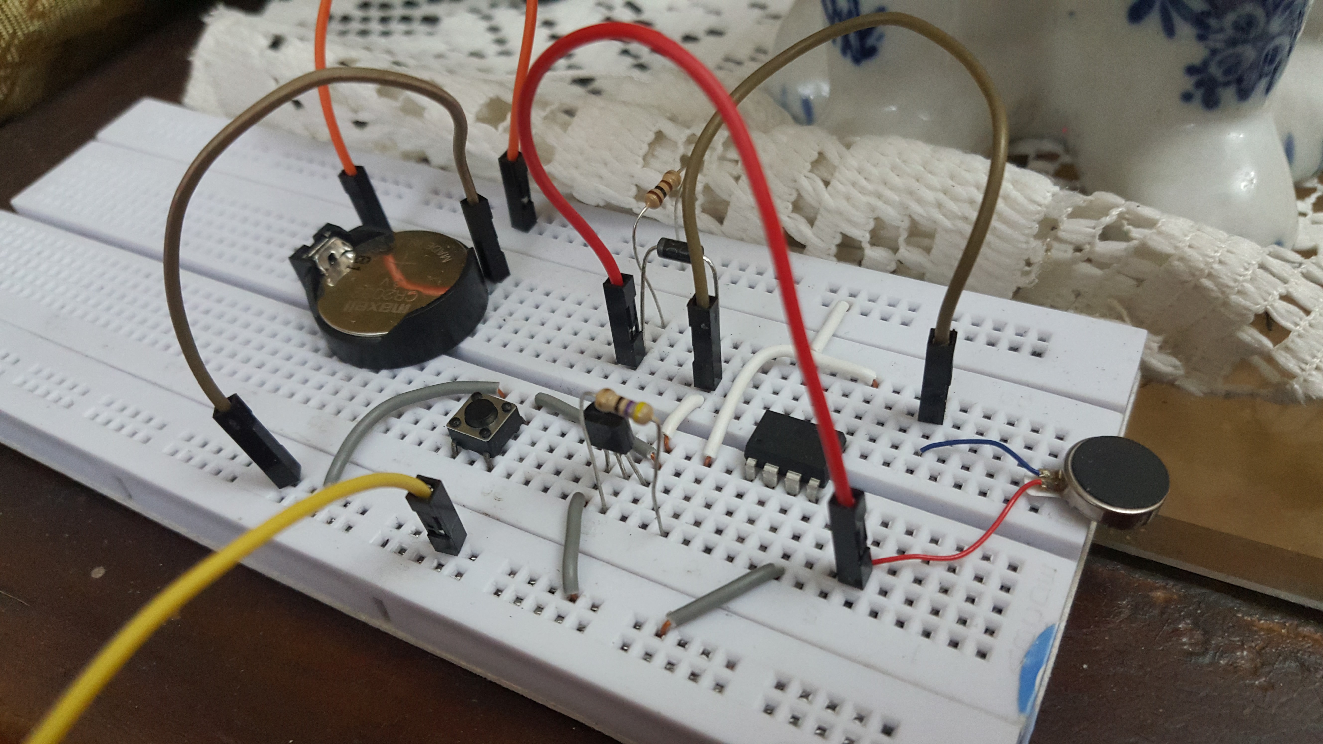
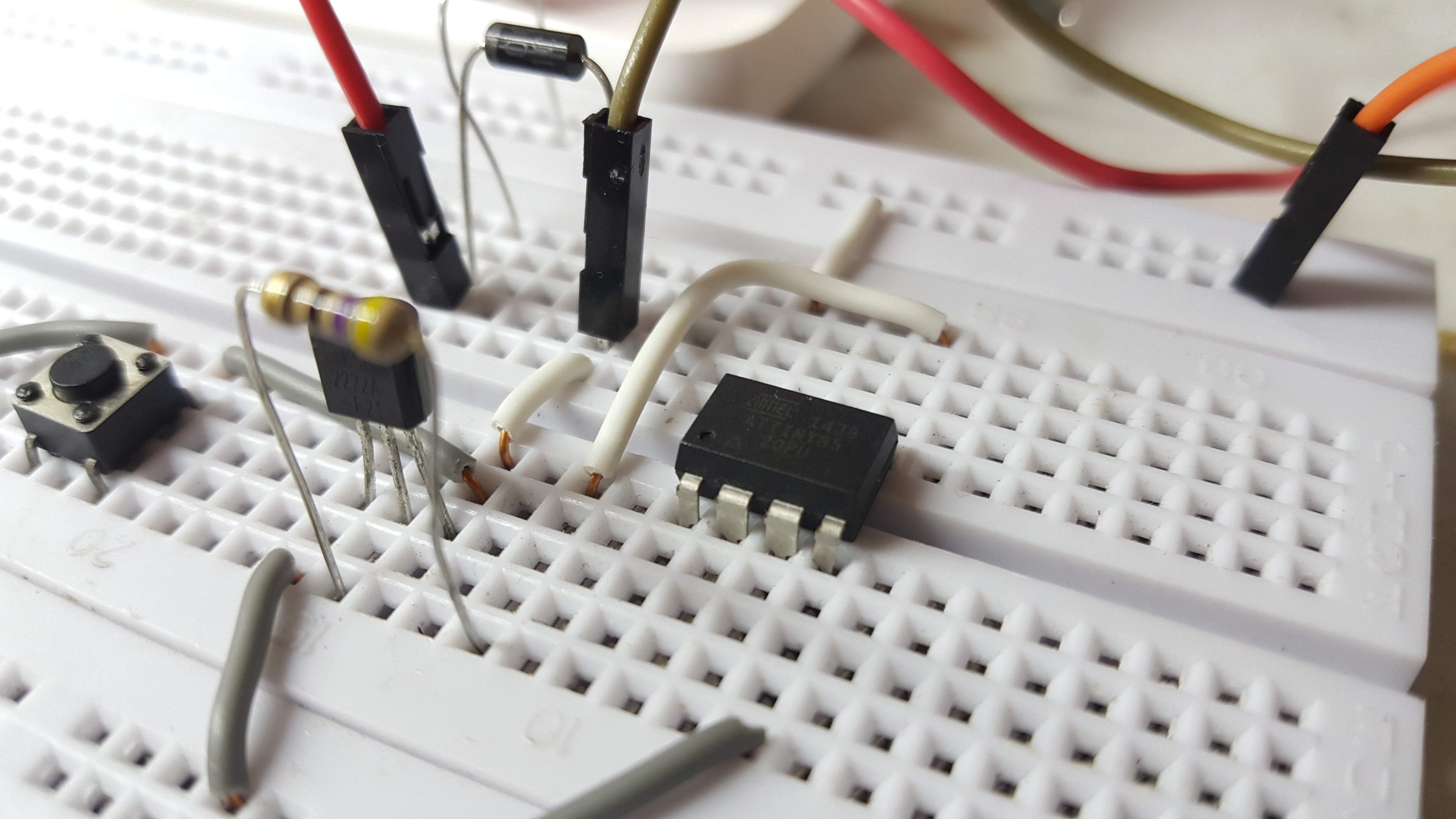
Measuring the unreliability of the ATTiny85's internal clock
03/07/2019 at 14:53 • 0 commentsI've read it countless of times: the internal clock on the ATTiny85 is very unreliable. It's said that it's accuracy vary wildly depending on various factors like temperature and voltage.
I still wanted to test it out for myself. I wanted to find out just how unreliable it is. And if it is possible at all to do some hacks to it to increase the accuracy. What followed was a lot of lessons learned mixed with frustrations.
![]()
First, a brief overview of what my project is about. TIRO (Time is Running Out) is a simple wearable that vibrates every 5 minutes to remind the user of the passage of time. I don't need exact intervals between vibrations, since the timing does not need to be exact (The user won't be able to tell if the vibrations were late or early, anyway),
---------- more ----------Before I began the experiments, I wanted to do some baseline tests. Note that the experiments were done multiple times but I've only picked out datasets that are important to us.
Legends: T1-T3 are the times when the vibrations started running. Tn is when the timing was already off by around 1 second. And Tx is the longest time I've let the circuit run for that trial.
This first iteration runs a motor for a duration of 0.5 seconds, waits 10 seconds using delay(), and then repeats.
Watchdog? Voltage Source Trial No. T1 T2 T3 Tn Tx No 3.072 V 1 00:10 00:20 00:30 02:31 12:44 No 3.072 V 2 00:10 00:20 00:30 02:21 02:41 The results are not showing too much promise as there is already a noticeable one second offset at around the 2 minute mark. The times as to when the offset happens also vary per trial which forced me to do multiple tries.
Later on I learned that the delay() function is not really suited for measuring delicate timings as it is a blocking function. I then updated my code to make use of millis() to determine how much time has passed before running the motor. The results were a bit more promising this time.
Watchdog? Voltage Source Trial No. T1 T2 T3 Tn Tx No 3.072 V 1 00:10 00:20 00:30 05:09 - No 3.072 V 2 00:10 00:20 00:30 04:39 - It's promising but still not enough. Plus, the offset is now negative instead of positive (05:09 instead of 05:11). I later figured out that maybe millis() was not granular enough so I made use of micros(), which showed a huge improvement.
Watchdog? Voltage Source Trial No. T1 T2 T3 Tn Tx No 3.072 V 1 00:10 00:20 00:30 26:41 36:51 No 3.072 V 2 00:10 00:20 00:30 21:49 23:59 Now this makes sense. micros() is just more precise but it surprised me just how big the improvement was. I did these tests a couple more times and they have been somewhat consistent.
These results can already be considered good for my purposes. There would only be a noticeable offset of one second by around the 20 minute mark. By this time, a lot of time has already passed for the user to care.
The experiments does not stop here though. The current setup consumes a lot of power and it's not ideal especially since we'll be running it off a 3V CR2032 Lithium Ion battery. The answer is to use a watchdog timer as the delay when the circuit is not running the motor (The power savings are huge, from 0.97mA to 4uA. More here).
This part took a lot of tests from me that played around with different settings of the watchdog timer (i.e. Using 8s to 16us) the table below shows the most promising results out of the whole series of tests.
Watchdog? Voltage Source Trial No. T1 T2 T3 Tn Tx Yes 3.180 V 1 00:10 00:20 00:30 06:01 24:02 Yes 3.180 V 2 00:10 00:20 00:30 06:01 23:02 You could say that the results got worse, but this is actually the best outcome out of all the iterations that I did. The reason for this is that the watchdog timer, in itself, is not really meant to be used this way. It definitely lessens the power consumption, but at the expense of the accuracy as it fires inconsistently. It's a classic catch-22 of accuracy vs lifespan.
![]()
I tried to do some tricks and hacks on the software side to try to make it as accurate as possible but all of them have failed. Different chips also show different results too which added more to the frustrations. It was at this point that I have accepted the fact that if I want accuracy, I have no choice but to use an external clock. Or I could just let it be.
The important thing for me is that I was able to test out personally just how unreliable the ATTiny85 internal clock can be. I might test out a circuit with an external clock in the future and compare the results. And after that, finally decide if my project is okay without it.
TIRO Vibrating Watch
TIRO (Time is Running Out) is a watch that vibrates every few minutes to remind the user that time in this world is quickly running out.
 There was actually too much room that I cut it so it's not too bulky. So it turned from this: