January 17, 2020
The Bin Level Monitor based on the VL53L0 has proven to be an ultra-low-power, accurate device for remotely keeping track of average fill level in a 1-meter-tall waste receptacle. But a long-standing problem with this device has been the need to mount the VL53L0 sensor on the case surface while the pcb is mounted on the case mounting posts; i.e, separately. So far I have been using small plated through-holes and soldered silcone-insulated wires between the pcbs. This works, and my one and only long-term test of the device used this method with success. But for a commercial device there needs to be a simpler (meaning cheaper) way to connect the two pcbs. I think I finally have the right design.
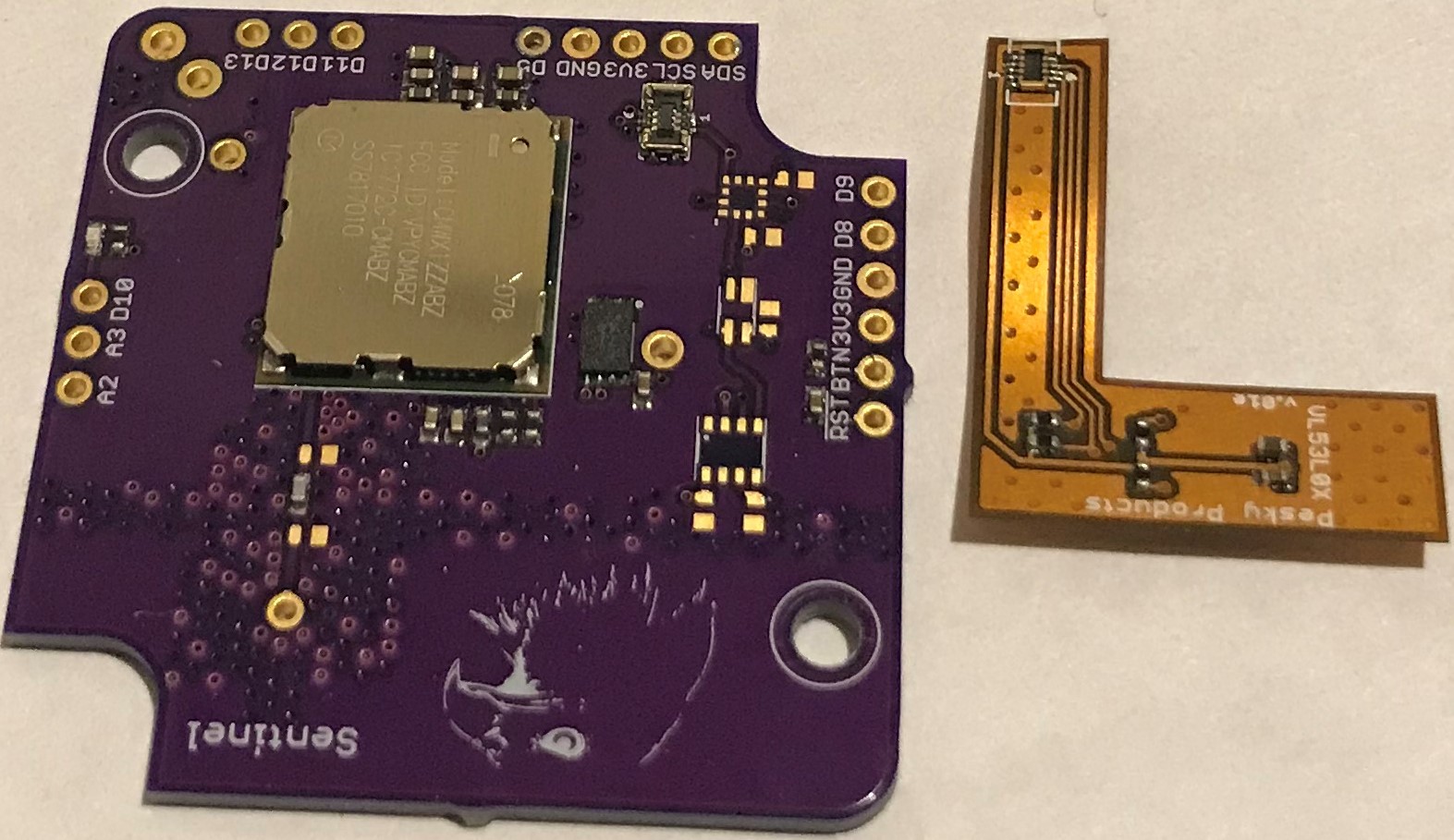
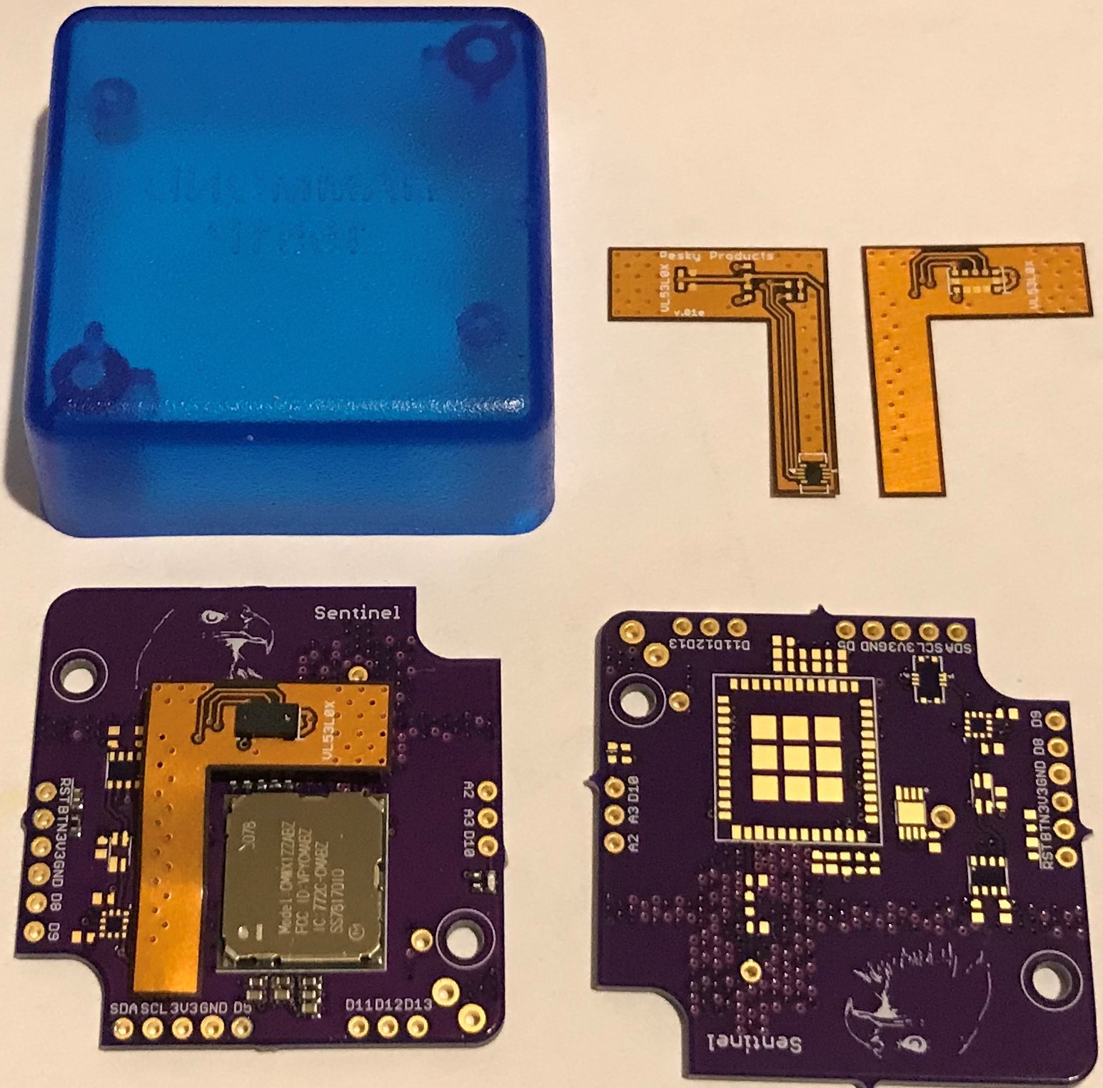
I redesigned the VL53L0 daughter board in flex and placed a small six-pin Molex flex connector at the end of a "dog leg" extension. With the corresponding mating connector on the main pcb, I worked out the geometry such that the VL53L0 daughter board could mount flush with the inside surface of the case as desired and simply "snap" into the main board. No more soldering individual wires.

It wasn't easy soldering these connectors, and I had to replace the one on the main board due to solder bridging on my first attempt. But in production this will all be handled by pick-and-place machines so the construction and design are what is important here. The BME280 pressure/humidity/temperature sensor, BMA400 accelerometer, and VEML6040 light sensor remain unpopulated in this build since I didn't really use these in the first trial.
I am not sure how robust the connector is once mated. I might have to add a drop of glue in production to ensure a sound connection in the event the bin lid is slammed or the bin falls down, etc. This might not be an issue because the main pcb is screwed into the case and the daughter board is taped to the inside case surface, and there shouldn't be any possibility of relative motion between the two. But this is TBD.

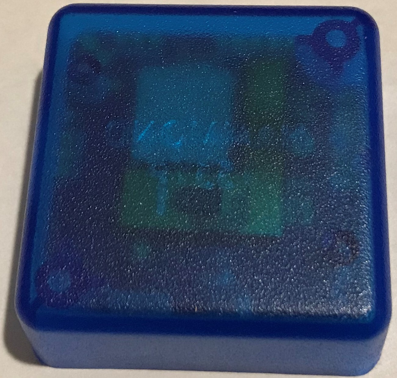
The length of the flex dog leg is the variable here since I am not sure what is the right length I need to fit into the well (still to be) machined into the bottom of the Hammond box. I want the beveled (the PMMA lens cover is beveled) penetration to lie right in the center of the box, and I will either have to bend to fit with the flex design I have or, possibly, shorten the dogleg a tad to comfortably fit into the well.

I asked my colleague Greg to machine one or two boxes for me and as soon as I get them from him I will assemble a complete unit, or at least try to do so. I think at worst I will have to tweak the design of the flex daughter board to optimize the length of the dogleg. But it looks like the design itself will work and will ease assembly in production as desired.
 Kris Winer
Discussions
Become a Hackaday.io Member
Create an account to leave a comment. Already have an account? Log In.