 Marcel van Kervinck
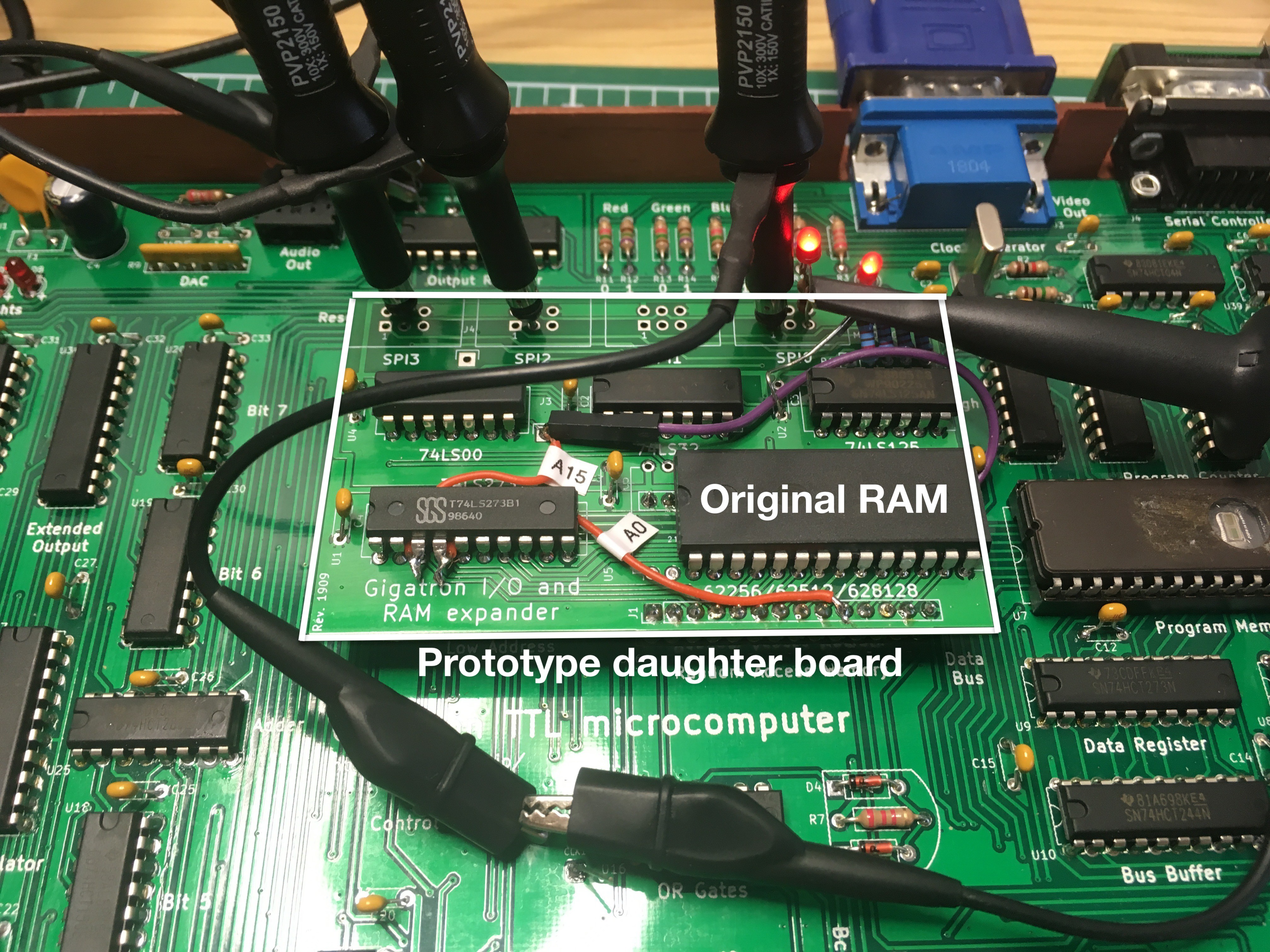
The board is now integrated. Regular pin headers won't fit in the machined RAM socket: a square peg doesn't fit a round hole, literally. You need machine pin headers. Luckily the local electronics shop had a couple. After fixing a cycle counting bug in the driver code, I decided on using the WozMon for testing the board. With an LED I could easily determine that I can drive the enable lines of each SPI port. The next step is to send data. Here is what it looks like:
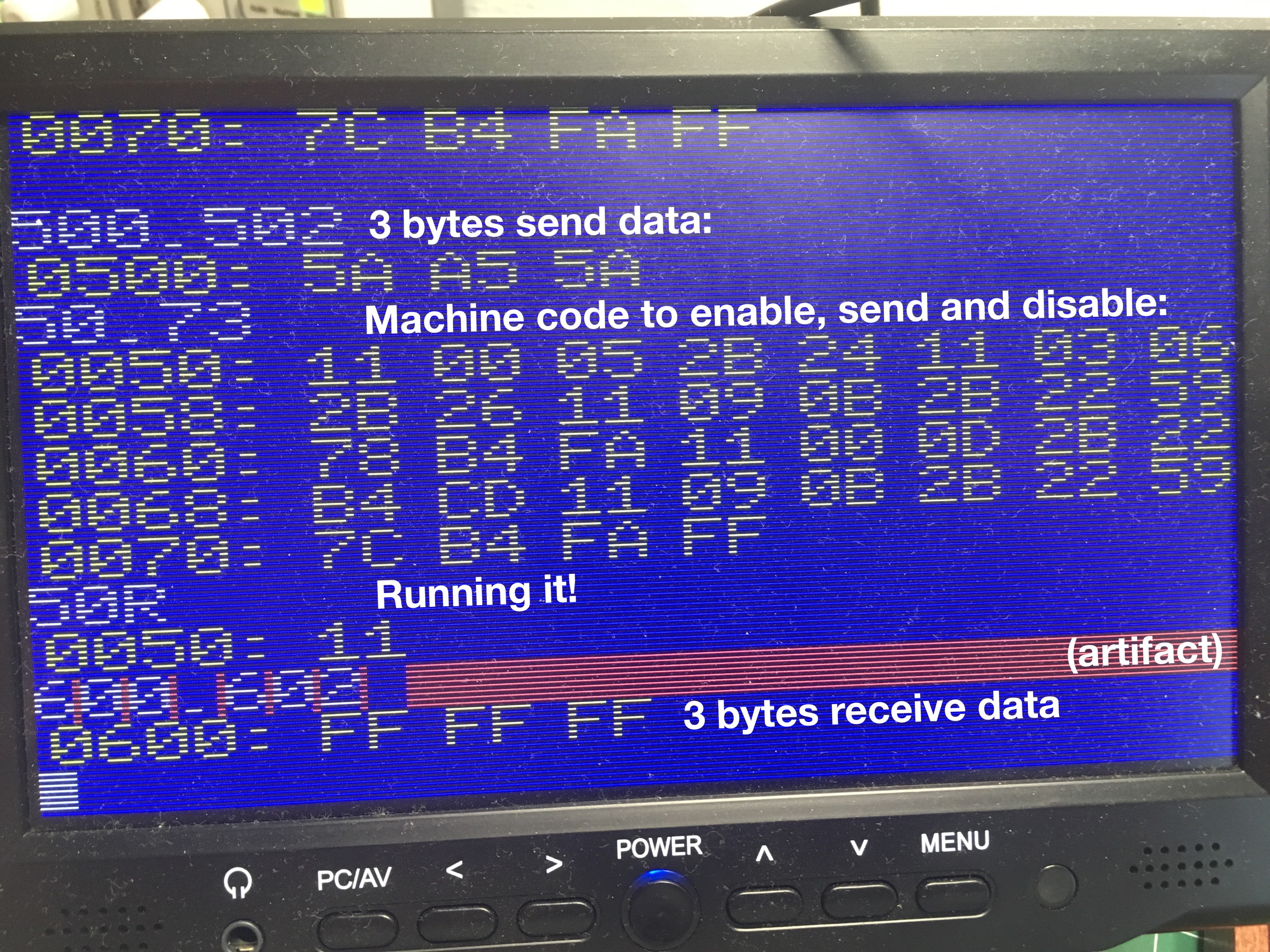
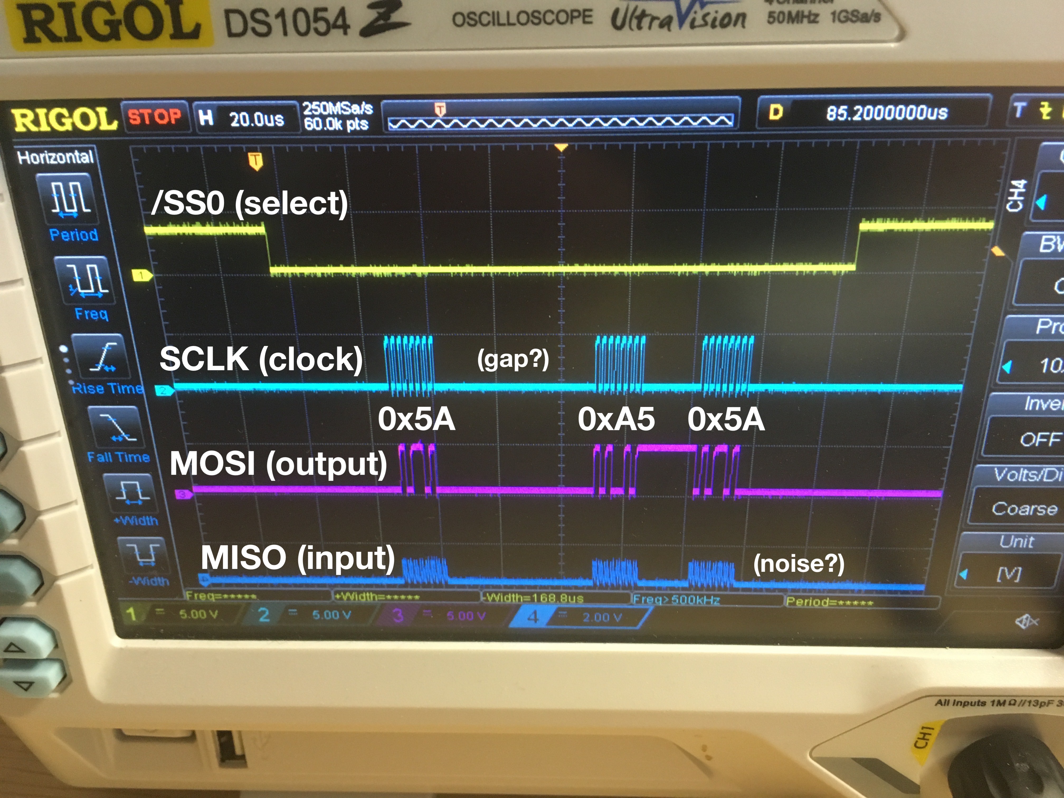
It looks promising on the scope. We are sending out the expected data while the Gigatron maintains its video signal. The longer gap is caused by a VGA pixel burst, during which the application is stalled. However, the input comes in as all-ones where we expect all-zeroes. The input lines looks noisy as well. As if the pull-down resistors don't do anything. [Edit: And that was exactly the case: bending over the resistors had broken off some of them.]
To be continued...
Discussions
Become a Hackaday.io Member
Create an account to leave a comment. Already have an account? Log In.