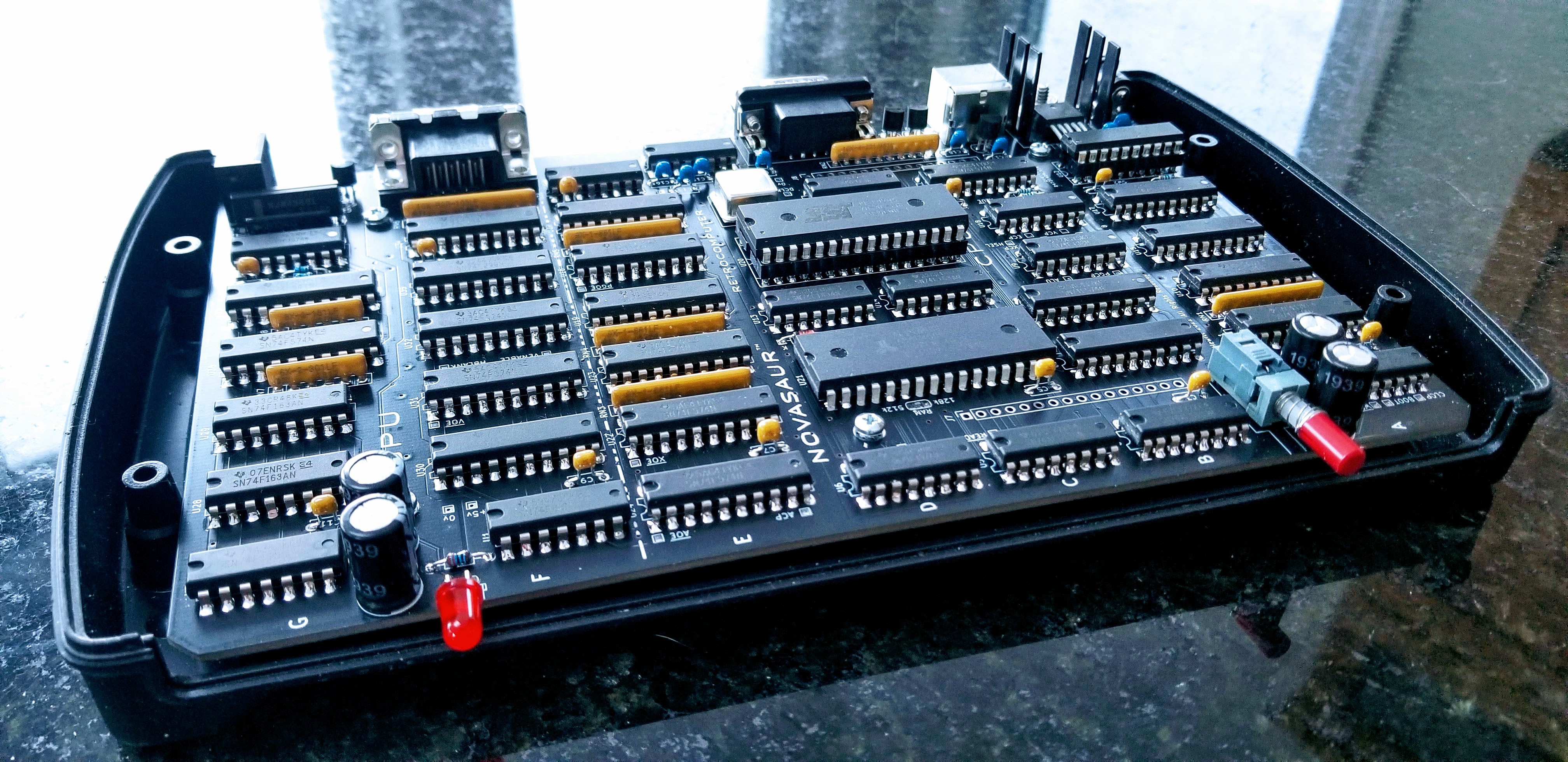
It's been a couple of months since the last update and more like three since anything meaningful changed. There has been (yet) another board revision and Rev. 8 is now good enough to actually solder the chips in place!

Just like last year, the project is coming out of a design phase and beginning the next stage of development. The past year focused on the firmware (hardware abstraction layer) and this year will focus on the operating system. This primarily involves bringing up CP/M, but there's a bit more to it than that...
Preemptive Multitasking
One advantage of the byte-code interpreter is the CPU state is already in RAM. This makes it easy to switch the CPU context and have more than one CPU running on the machine. The banked memory provides up to 8 banks of 64k and each bank can be assigned to a separate CPU instance.
A counter is incremented at the end of each virtual process block (every 4 lines in SVGA) and the context is switched every 75 blocks. The context is determined by a sequence of 256 that can be set up to prioritize how often each CPU runs. This sequence takes up to 2 seconds to complete, but would typically repeat faster since each CPU can yield before the block count gets to 75.
The context switch takes advantage of the 2-cycle identity function to read/write from the zero page to an adjacent memory location in a single instruction. This allows a entire context switch to be completed in under 80us. The context switch is also the only time the memory bank can be changed and will prevent another process from accessing or modifying another's memory.
This memory segmentation is very important since half the memory banks are used as a disk drive. Without segmentation a crashed user program could write to the memory and damage the file system.
Shared Memory
Bank 0 contains the display and state of the hardware abstraction layer. This state is in a protected area above 0xF0 in the memory and also contains the context for each CPU. There is no context for bank 0, so this is used to hold the context sequence to determine the next CPU context.
0xF0: Context Sequence
0xFn: Context n (1-7)
0xF8: Keyboard Scan Code Buffer
0xF9: Keyboard Character Buffer
0xFA: Serial Receive Buffer
0xFB: Serial Transmit Buffer
0xFC: TBD
0xFD: TBD
0xFE: TBD
0xFF: Zero Page (HAL state)
Each CPU context is broken down as follows:
[0x00 ... 0x7F] [0x80 .... 0xE7] [0xE8 .. 0xEB] [0xEC . 0xFE] [0xFF]
<-record body->|<-message body->|<-msg header->|<-CPU state->| flag
The top 128 bytes is a fixed buffer used for transferring records. The next two sections can contain a message used for inter-process communication; consisting of a variable body up to 104 byes in length and a header containing message metadata. The next 19 bytes contain the CPU state. The final byte is a binary semaphore to signal (0) or wait (-1).
Kernel
Each CPU can only access its own context. However, the first CPU (bank 1) has an additional privilege to access the context of the other CPUs (2-7). This first CPU runs a kernel to manage and coordinate inter-process communication between the other CPUs (master/slave configuration).
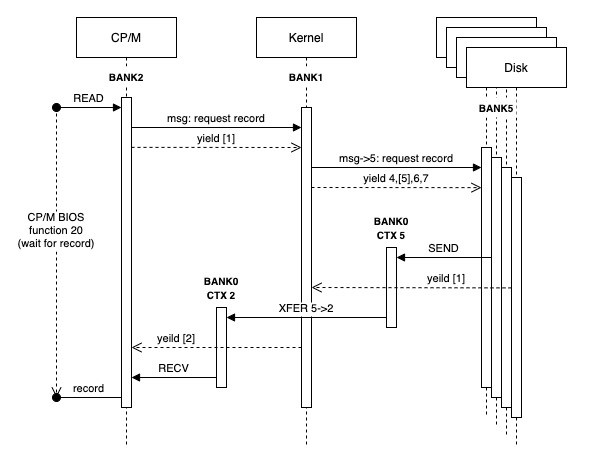
One bank (2) is configured to run the CP/M operating system and the last four banks (4-7) run a process to manage the memory as a RAM disk (designated as the A: drive). The following diagram shows how CP/M would request a record from the RAM disk using a context sequence of 2:1:4:5:6:7:1.

The CP/M context would publish a message to request a record and then yield. Yielding involves timing out the context block count and setting the semaphore flag to -1 (wait). The CPU is now halted and blocked in the wait state until a signal (0). The context switch would then happen at the end of the current process block.
The next context is the kernel. The kernel operates in an event loop checking the messages from each of the other CPUs (2-7). The kernel sees the message from context 2 (CP/M) and determines which CPU disk instance holds the record. A message is written to that CPU context (e.g. 5) and the flag set to signal. The kernel then yields, but does not halt. The kernel always remains in the the event loop.
The context switches from 4-7 in sequence where most of these CPUs would be halted in the wait state. Context 5 will see the signal though and consume the message. This would result in the record being read and written to context 5 along with a message. This CPU would then yield.
The next context switch is back to the kernel and the event loop. The kernel picks up the message from context 5 and understands this was a request from context 2. The record is transferred from context 5 to 2 and a message is posted to context 2 with the signal.
The final context switch in this sequence is back to CP/M (context 2). The signal has unblocked the CPU and the record is received by copying it to the CP/M file buffer. From the point of view of CP/M, the call to BIOS function 20 returned with the file buffer filled as if it had initiated a request to a disk controlled and then blocked on the IO.
A final note on performance. The record is transferred three times here, but this is done with an extended instruction using native code at one byte per virtual machine cycle. This example requires around 60 process blocks to complete including all the context switching. That's around 6.25ms, or 20k bytes/sec. That doesn't sound very fast, but it's comparable to a floppy disk of the era at around 16k bytes/sec.
The yield and event loops are also handled with extended CPU instructions, so each context switch should fit in a single block. The context switches would take 6 blocks to complete after 75 blocks of CP/M if it doesn't yield. The context switching would therefore account for up to 7.4% of the resources. However, the CP/M process can be extended by adding a null to the context sequence after the context 2 entry (1:2:0:1:4:5:6:7). CP/M would then run for up to 150 blocks before switching and reduce the context switch overhead to just 3.8%.
 Alastair Hewitt
Discussions
Become a Hackaday.io Member
Create an account to leave a comment. Already have an account? Log In.