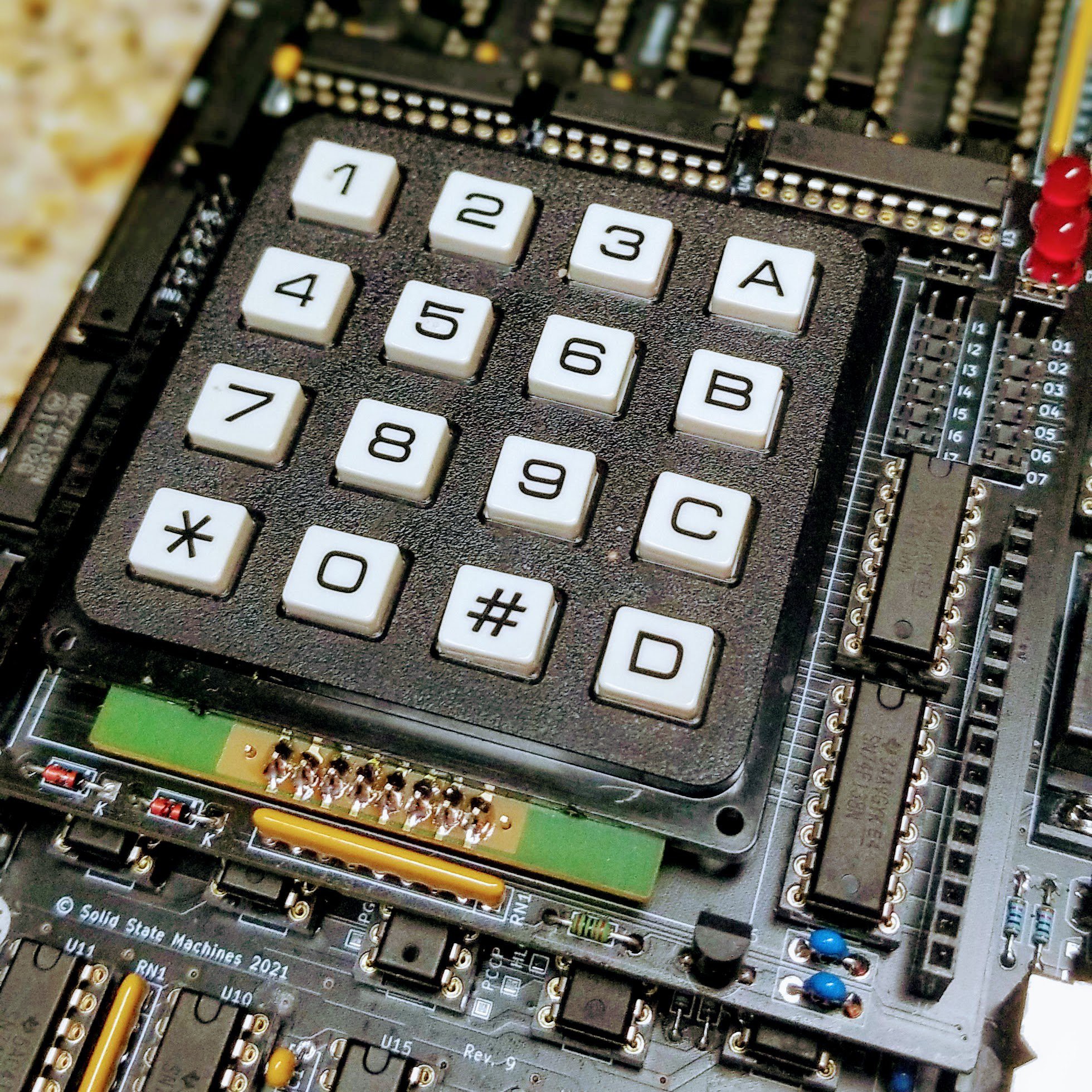
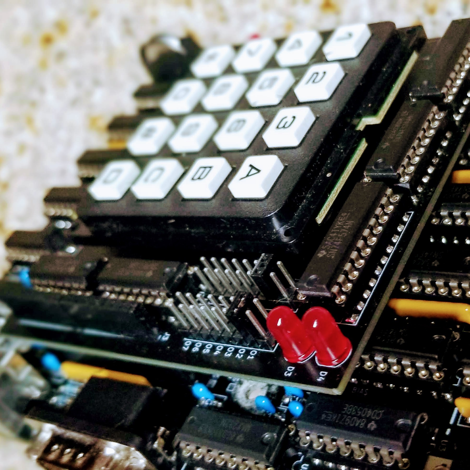
This is a follow up to an 18 month old log describing an expansion board. An initial version was built way back alongside the Rev. 2 board to test the electrical interface. The plan was to use the numeric number pad as a stop-gap keyboard for testing until the PS/2 keyboard scan code was completed. In the end the project pressed forward to build out the PS/2 interface and the expansion board was forgotten.
Fast forward to Rev. 9 and a new version of the board was built with some minor adjustments. The main regulator is maxed out, so the 6V supply is now passed to the expansion board and a local LDO regulator is used to power the board.

The original design also used a pair of 16-pin headers to connect the board. A more cost effective option is to use two pairs of 8-pin headers. These headers are standard on the Arduino and in plentiful supply.

This expansion board is now easy to access thanks to the I and O commands in the 8080 monitor. These commands read and write to the input/output ports, where ports 1-7 represent the seven available expansion registers.
This test board uses register 7 to scan the keyboard matrix and provide a couple of badly needed blinkenlights. A pair of jumpers are used to map a single 8-bit flip flop to any of the other expansion registers. There is also a header to break out the 8085 interrupt lines (still needs testing).
 Alastair Hewitt
Discussions
Become a Hackaday.io Member
Create an account to leave a comment. Already have an account? Log In.