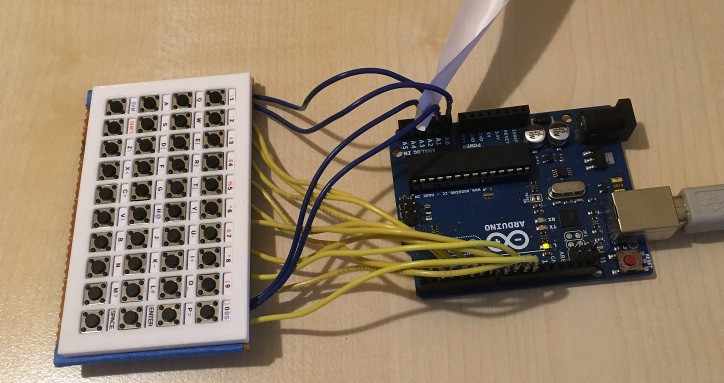
In the last log I covered how a keyboard is wired up. This time I'll cover how it is scanned. My prototype thumb keyboard has four rows of ten keys each, giving a requirement for 14 GPIOs in total. This puts it within the capabilities of an Arduino. There won't be many pins left for anything else, but I'll cover a way around that in a later log.

Prototype 1 connected to an Arduino UNO. The piece of paper is just there to stop two of the pins shorting out.
To scan the keyboard, all the GPIOs are first set to INPUT_PULLUP, then each row GPIO in turn is set to output and pulled LOW and each column GPIO is read. A column GPIO that is LOW indicates a pressed key. The row is then set pack to INPUT_PULLUP and the next row is scanned. The end result of this is a map of pressed keys.
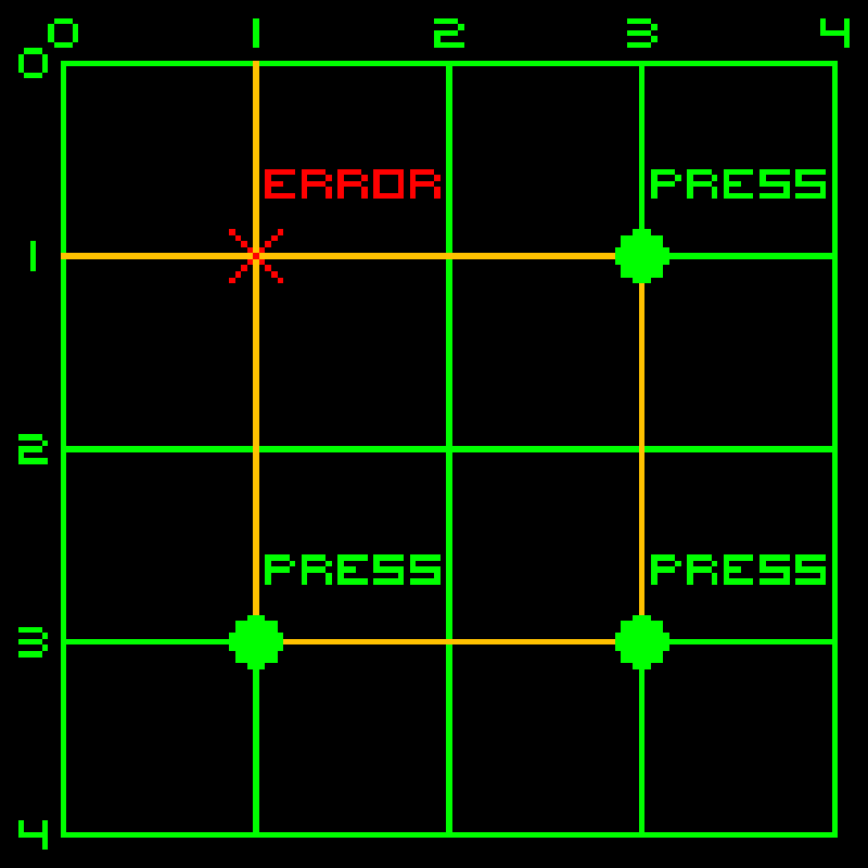
But there is a problem: if three keys are pressed together forming three corners of a square, a fourth, phantom (or ghost) key press will be detected at the missing corner. Here's a diagram to help explain that:
 In this example, keys are pressed at (c3,r1), (c3,r3) and (c1,r3), but when position 1,1 is scanned current will flow via the three pressed keys (orange line) and produce a phantom key press at (1,1).
This situation can be avoided by fitting a diode in series with each key switch. This means that current can flow from a row to a column but not the other way. Looking at the example above again, when (1,1) is scanned, current could flow from row 1 to column 3 at (c3,r1) but would not be able to flow onto row 3 at (c3,r3), so no circuit would be made.
Most keyboards, including mine, do not do this and rely on detecting the phantom instead. This is quite easy to do: for each key, if two or more keys are pressed in same row and one one of those keys also has another key pressed in the same column then a potential phantom exists. Referring to the example above again, (c3,r3) would trigger phantom detection as it has a another key pressed in the same row at (c1,r3) and also in the same column at (c3,r1). When a phantom condition is detected, the scanning routine stops updating the state of the keyboard until the condition is cleared by releasing one of the keys.
Even with the phantom key problem, any two simultaneous key presses can be detected. As I'm building a thumb keyboard, and two is the usual number of thumbs per person, I think adding series diodes would be overkill in my case.
As this point we have the ability to determine which keys are pressed. In the next log I'll cover how this is turned into a series of key press, release and repeat events.
 David Boucher
Discussions
Become a Hackaday.io Member
Create an account to leave a comment. Already have an account? Log In.