 Luca
Luca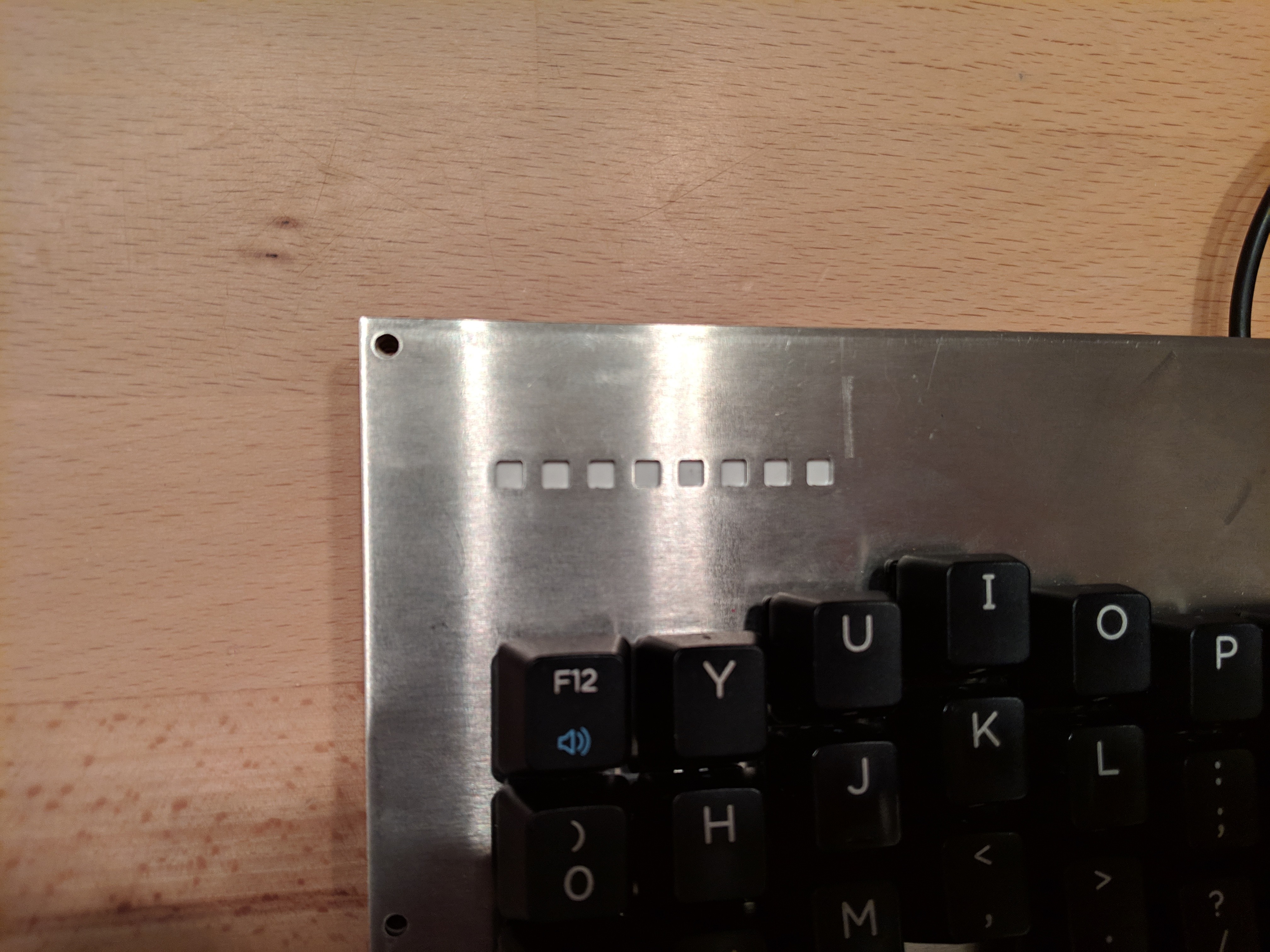
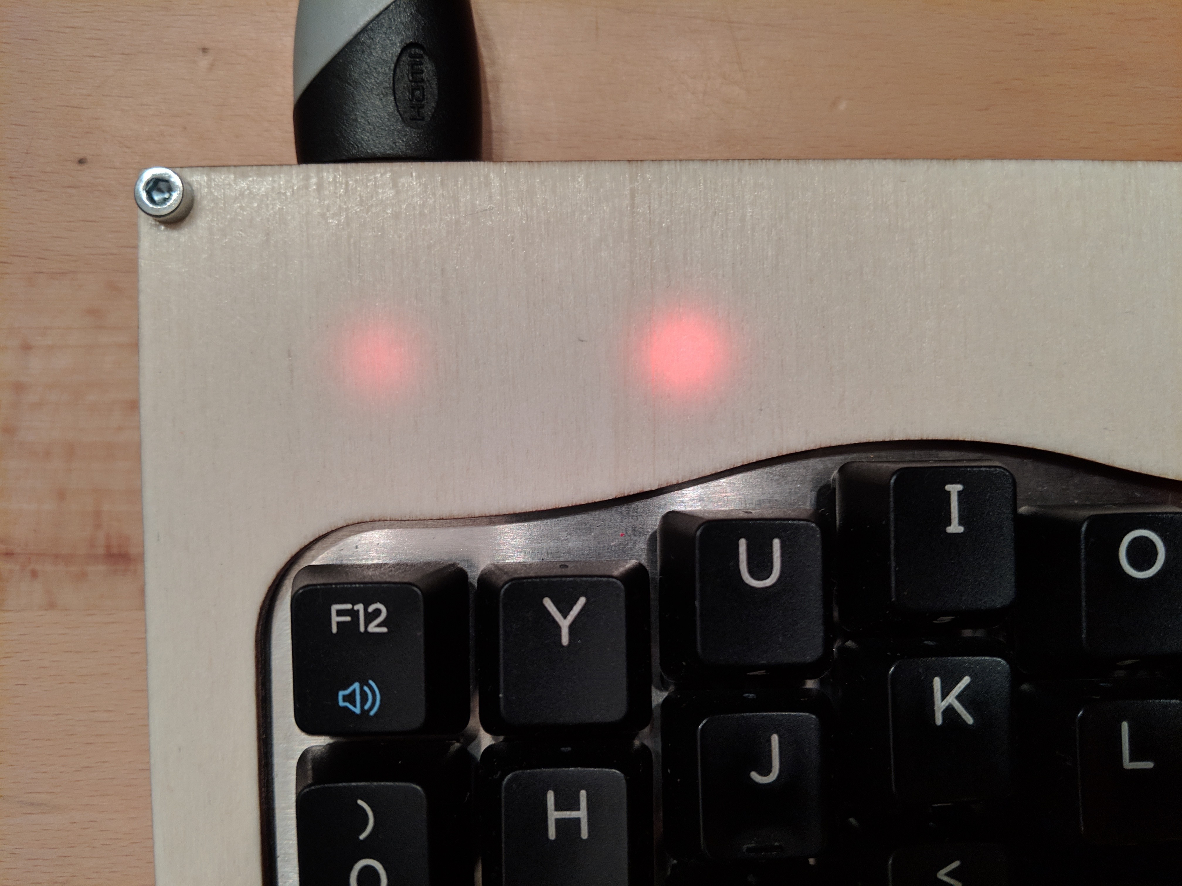
The top of the right metal plate has holes for the light of the LEDs. The white is the double side tape. In the back is placed the strip.
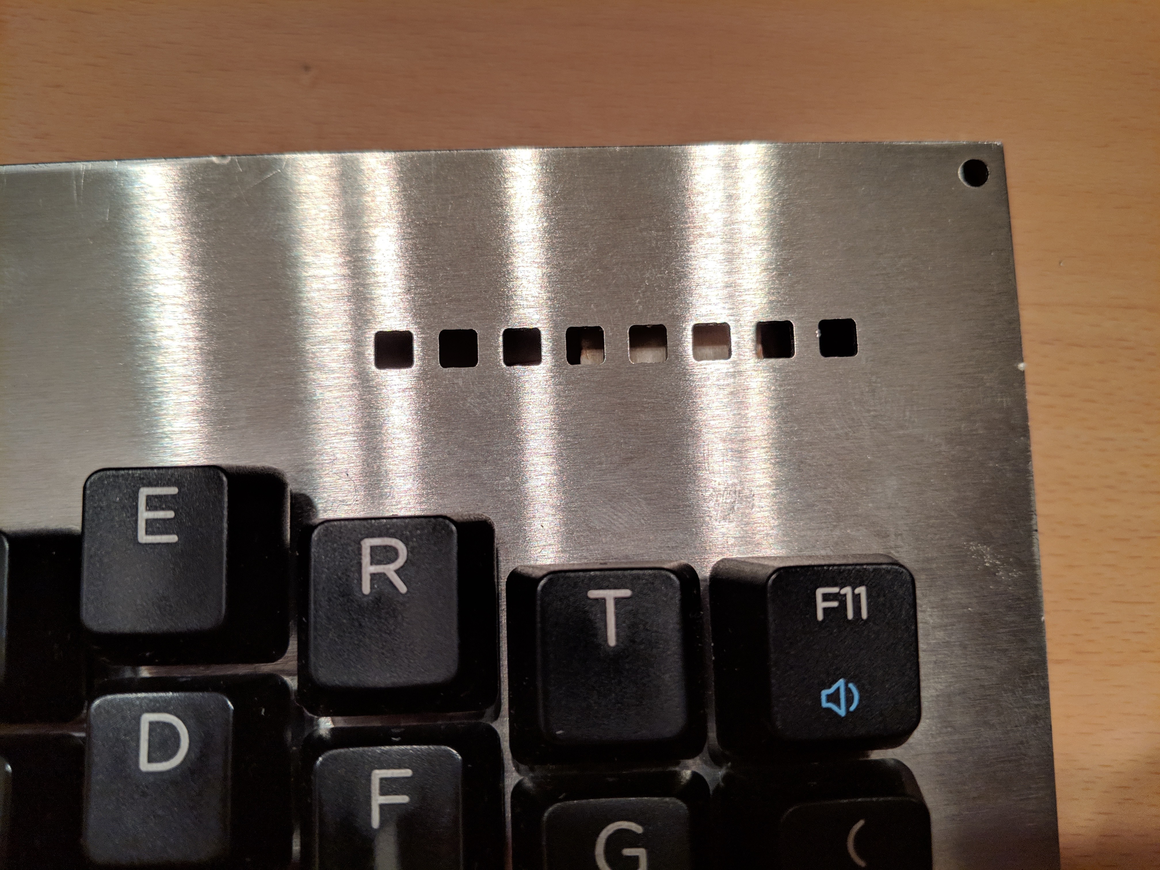
Also the right side has the holes, but no LEDs have been installed. The 8 ones of the other side are enough.
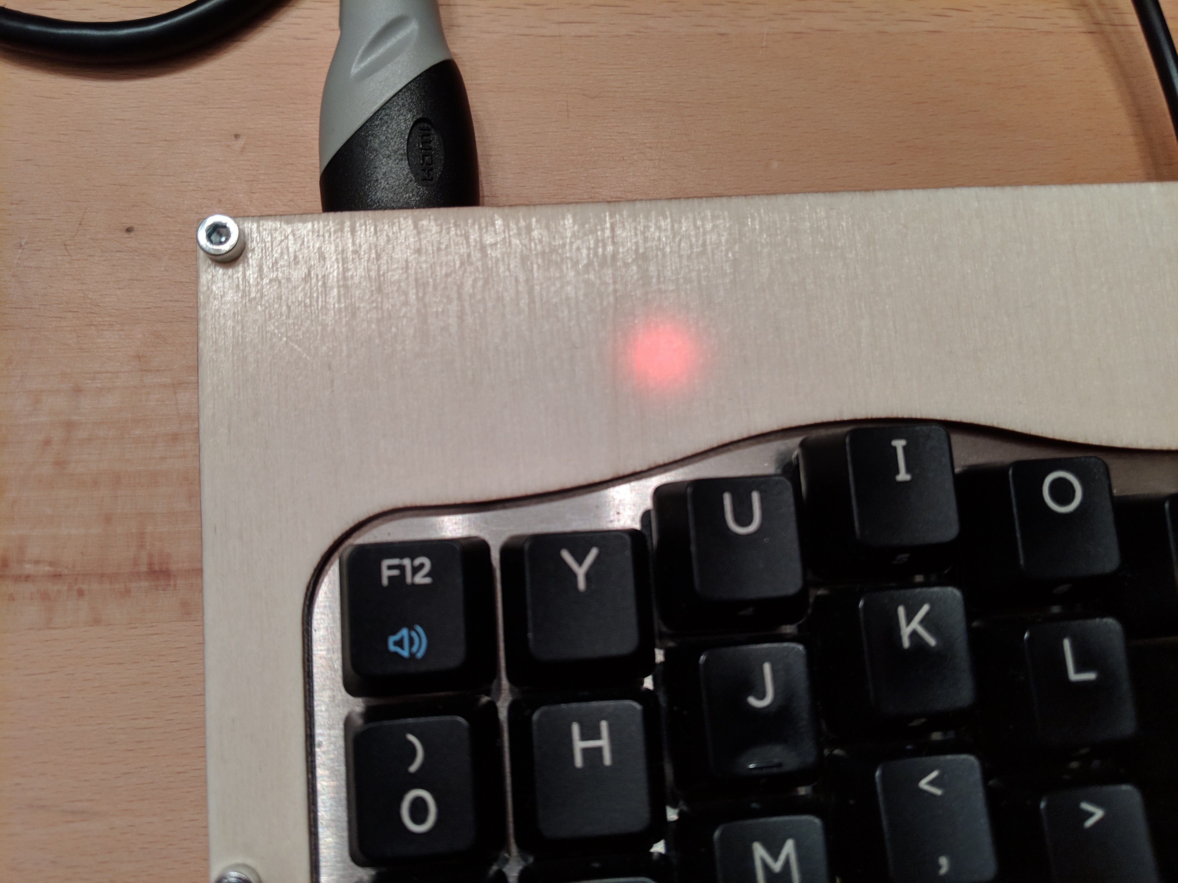
Some LEDs have just 2 states: 0% or 100%. They are used to inform which layer is currently active.
Others could have 3 states: 0%, 50%, or 100%. They are used for the One Shot Modifiers.
More informations about this feature could be found in the help pages of the firmwares that I'm going to use, QMK and Kaleidoscope. For example here the modifier is in the fixed state, hence at 100%.
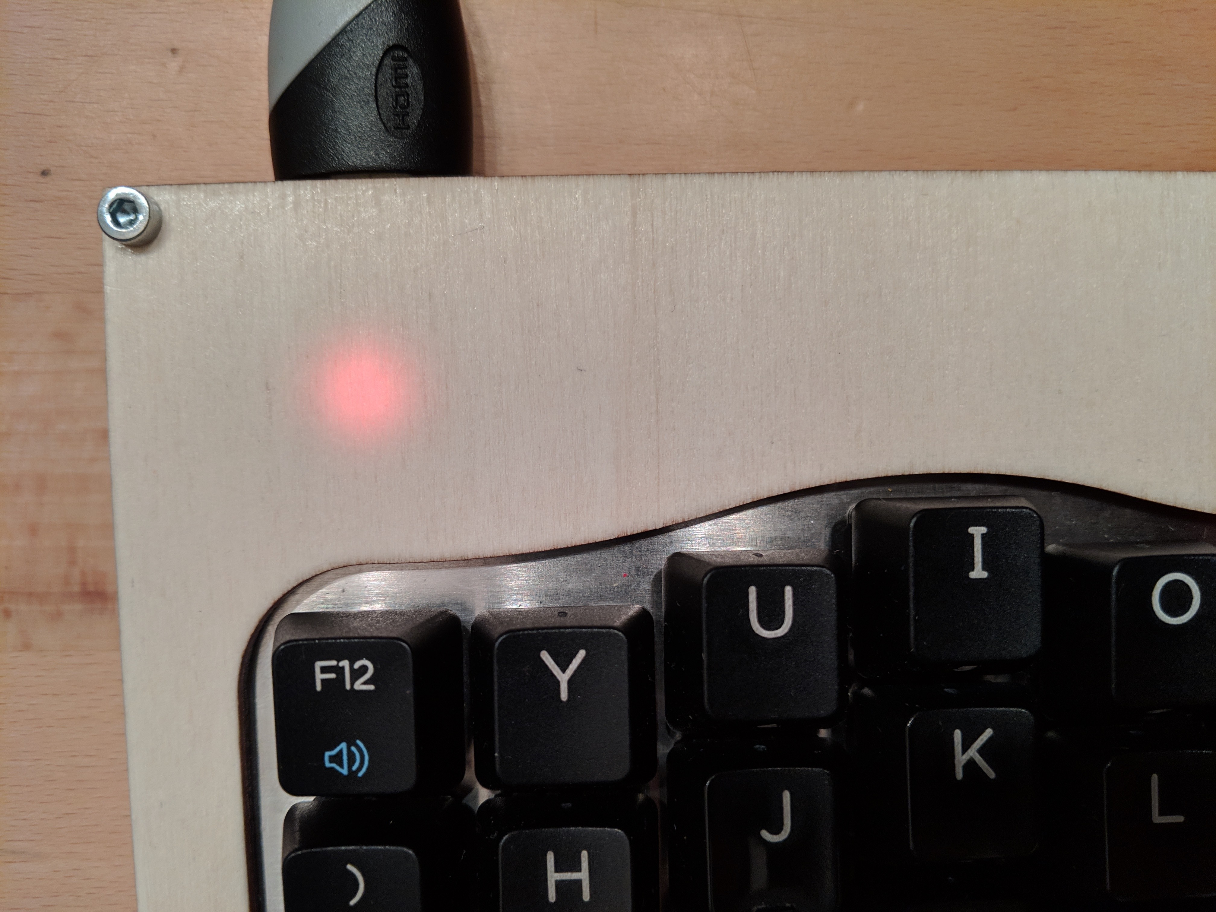
Here, instead, the modifier is in the "one key" state, hence just 50%. On the other side, an extra layer is active, hence the other LED is to 100%.
Discussions
Become a Hackaday.io Member
Create an account to leave a comment. Already have an account? Log In.