 Ross Bamford
(EDIT: This log is wrong. I was obviously not thinking properly when I wrote it. The full story is in the next log but TL;DR is that it's four memoy cycles, not four clock cycles).
As discussed in the previous log about the address decoder, I need a way to hold a /BOOT line low for the first four clock cycles after a reset. This means using some kind of counter.
I don't have any of the 7400-series counters to hand, and neither does my awesome local electronics store at the moment, but what i do happen to have is a ton of 74LS174 hex D-Flip-flops (with common reset, unlike the 72LS74). So I'm just going to add one chip and use five of the flip-flops instead.
I've not even EAGLEd this yet, but the concept looks like this in Logisim (when the reset line is active):
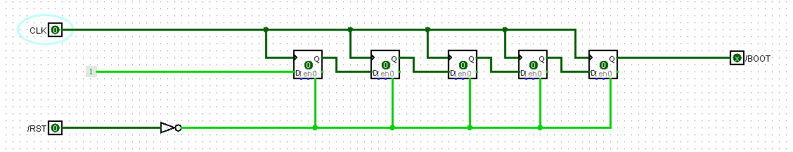
And, after reset goes high and the first couple of clocks have passed, /BOOT is still low:
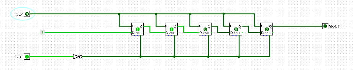
But from the fifth clock onward, /BOOT goes high, and stays high, until /RST goes low again.

This is pretty simple (it's really just a 5-bit shift-register with its input tied high) and stays with my philosophy of trying to work with what I've got, rather than reaching out for another IC that does what I need, but probably stuff I don't need, too.
Anyway, the theory's there. I'll find out if it works once the rest of the parts for the address decoder arrive and I can actually build it.
Discussions
Become a Hackaday.io Member
Create an account to leave a comment. Already have an account? Log In.