Ross Bamford
-
Arduino IO Device
04/07/2020 at 19:59 • 0 commentsI'll keep this one brief as I've already written a long post about it elsewhere (all the gory details can be found there), but I spent far too much of the weekend making an Arduino talk to the rosco_m68k as an IO expansion (i.e. mapped into IO space and communicating with the CPU over the bus).
This exposed a(nother) couple of issues with the board - IODTACK really needs to be exposed on the expansion connector, and the glue logic is a bit quick to drop DTACK when an address in IO space is no longer being strobed, but generally speaking once I'd figured those things out it went pretty well and I was able to get the Arduino to act as a simple single-register, write-only device connected to the m68k.
The timing issue probably won't affect real hardware devices, and the IODTACK issue can be easily worked around so no need to re-do any boards at the moment, though I've raised issues on GitHub to address them at some point in the future.
-
Fake MC68010s!
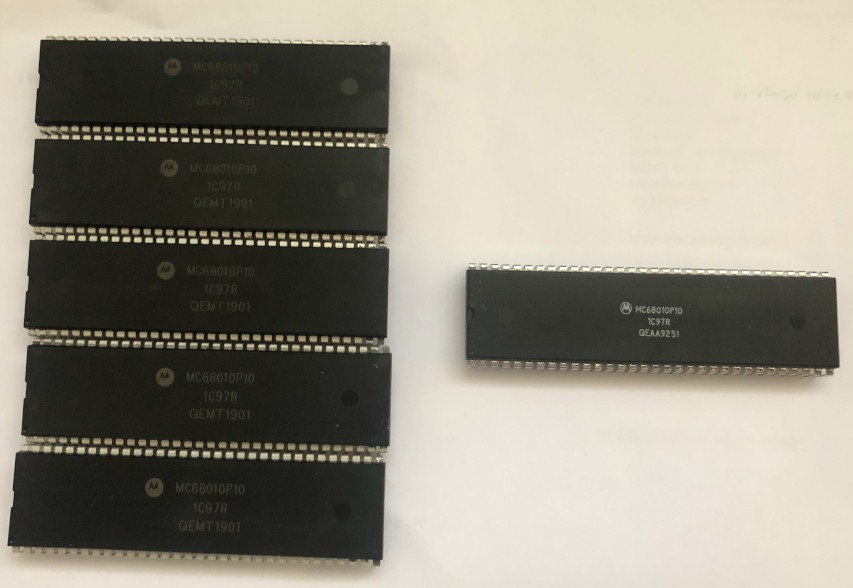
04/07/2020 at 17:42 • 1 commentSo I'm currently gathering parts to hopefully start offering kits on Tindie, and while most of the bits can be ordered directly from Farnell, some are more tricky to get hold of - especially the MC68010 and MC68901, since they're no longer in production. So I resorted to eBay, and received the first shipment of six MC68010s today. On opening the package, I was.... suspicious.
![]()
These are the six ICs I received. On the right is a genuine MC68010P10. On the left are five that are either fake, or just rebadged, 68000s. The things that immediately made me suspicious:
- The Motorola logo is incomplete
- The font isn't right
- The date code suggests these were made in week 1, 2019 (or possibly 1919!)
You can't see it in this picture, but the surface of the ICs is also rough, suggesting the original markings have been removed.
Sure enough, I threw them into a board and ran a quick software test which verified that these are, in fact, 68000s. They seem to work fine as 68000s, but trying to do anything 68010-specific (setting the VBR in my tests) results in an immediate illegal instruction exception.
Fake ICs are sadly a fact of life, and luckily I'm working with my own design which explicitly specifies the 68010. I know that people buy these as an "upgrade" for Amigas and such, and I worry that people who do that will likely never know they're running a fake, as the software for those computers won't usually use any 68010-specific features.
This bit of code will check whether you have a 68010 or not:
    movea.l #$20000,A0                ; Use $20000 as vector base...
    movec.l A0,VBR                    ; ... and load into VBR
If run on a 68000, this will cause an illegal instruction exception.
Because I felt like verifying that setting VBR actually worked too (unlikely it wouldn't I guess but y'know, completeness), I decided to expand this a bit to check these chips on the rosco_m68k:
MFPBASE     equ     $F80000

  ifd REVISION_0
MFP_GPDR    equ     MFPBASE+$01
MFP_IERA    equ     MFPBASE+$31
MFP_IERB    equ     MFPBASE+$09
MFP_ISRB    equ     MFPBASE+$05
  else
MFP_GPDR    equ     MFPBASE+$01
MFP_IERA    equ     MFPBASE+$07
MFP_IERB    equ     MFPBASE+$09
MFP_ISRB    equ     MFPBASE+$11
  endif

    section .text

; Entry point here!
kmain::
    move.w  #$2700,SR                 ; Disable interrupts
    movea.l #$20000,A0                ; Use $20000 as vector base...
    movec.l A0,VBR                    ; ... and load into VBR
    move.l  #TICK_HANDLER,$20114      ; Set up tick handler
    move.w  #$2000,SR                 ; Re-enable interrupts

.LOOP
    bra.s   .LOOP


GENERIC_HANDLER:
    rte

TICK_HANDLER:
    move.l  D0,-(A7)                  ; Save D0
    move.w  $408,D0                   ; Read SDB byte 8
    tst.w   D0                        ; Is it zero?
    bne.s   .TICK_HANDLER_DONE        ; Done if not

    ; counted to zero, so toggle indicator 0 and reset counter
    bchg.b  #0,MFP_GPDR
    move.w  #25,D0

.TICK_HANDLER_DONE:
    sub.w   #$1,D0                    ; Decrement counter...
    move.w  D0,$408                   ; ... and write back to SDB
    move.l  (A7)+,D0                  ; Restore D0
    move.b  #~$20,MFP_ISRB            ; Clear interrupt-in-service
    rte                               ; We're done
(full code here)
Right... Back to trying to get hold of some CPUs for these kits I've been talking about.....
-
Kits coming soon!
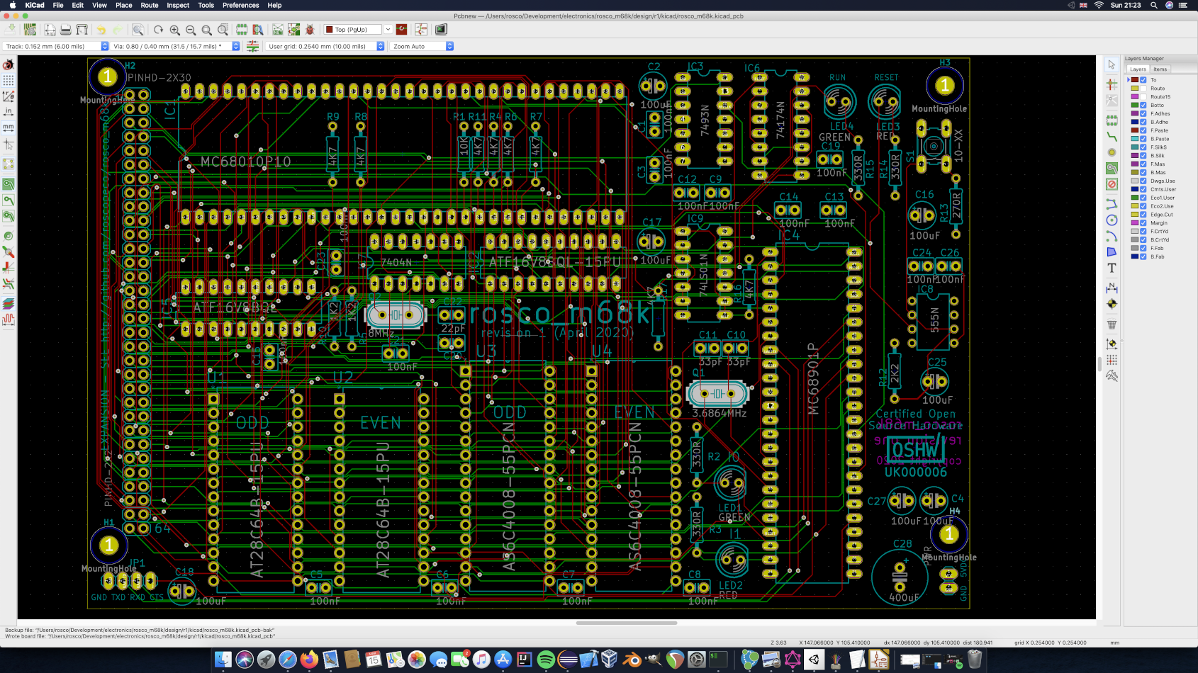
03/29/2020 at 19:01 • 0 commentsThe revision 1 PCBs I mentioned previously took about a week to arrive from JLCPCB, and I'm just as happy with them quality-wise as I was with the revision zero boards. They also represent the first boards that were designed (well, updated) in KiCad and exported for manufacture from there, and I'm pleased to say there were no unforeseen issues. I'm really liking KiCad now I've gotten used to it, and don't miss EAGLE at all.
With this milestone passed, I'm looking to start offering the computer in kit form on Tindie! The first iteration will be a sort-of "dev kit", in that it will be most suitable for hackers and devs, and I've been hard at work getting the software tidied up in preparation for that. The kits will come pre-loaded with the serial boot loader firmware and I've put together a "starter project" to easily spin-up an assembly or C project that's compatible with that so it'll be really easy to get started with the board.
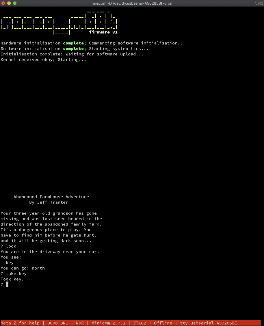
That said, it's not all work and no play - I've also spent a bit of time porting some recreational software. Here's a screenshot of Jeff Tranter's 'Adventure' running on the r1 board, loaded via Kermit:
![]()
With lots of new development in the firmware and software, as well as the hacker-friendly improvements in the revision 1 board (GPIOs, timers, external interrupt capabilities and compatibility with "legacy" MC6800 peripherals included!) there's a lot of fun to be had with this board. I hope to be shipping kits in the next couple of weeks, and will update here as soon as I can.
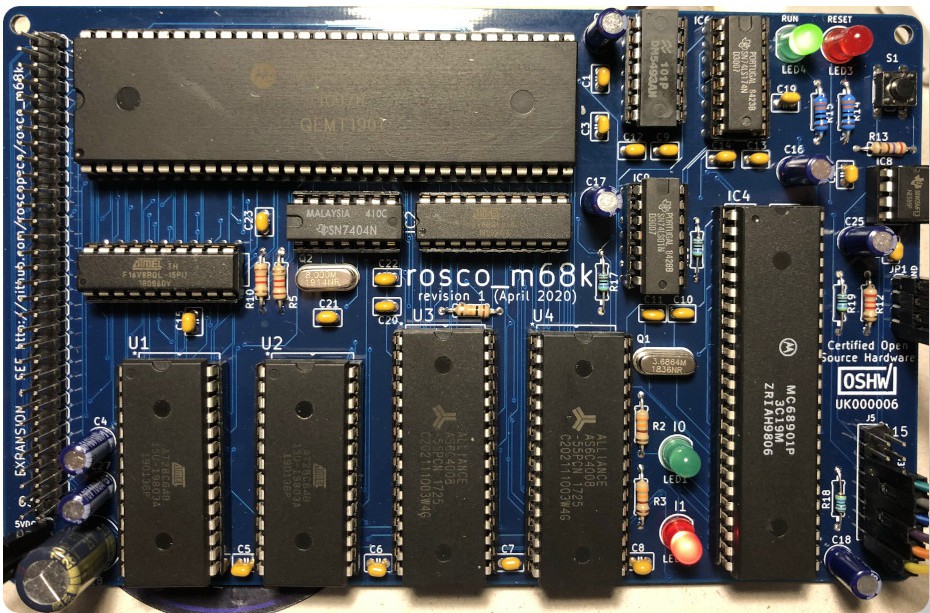
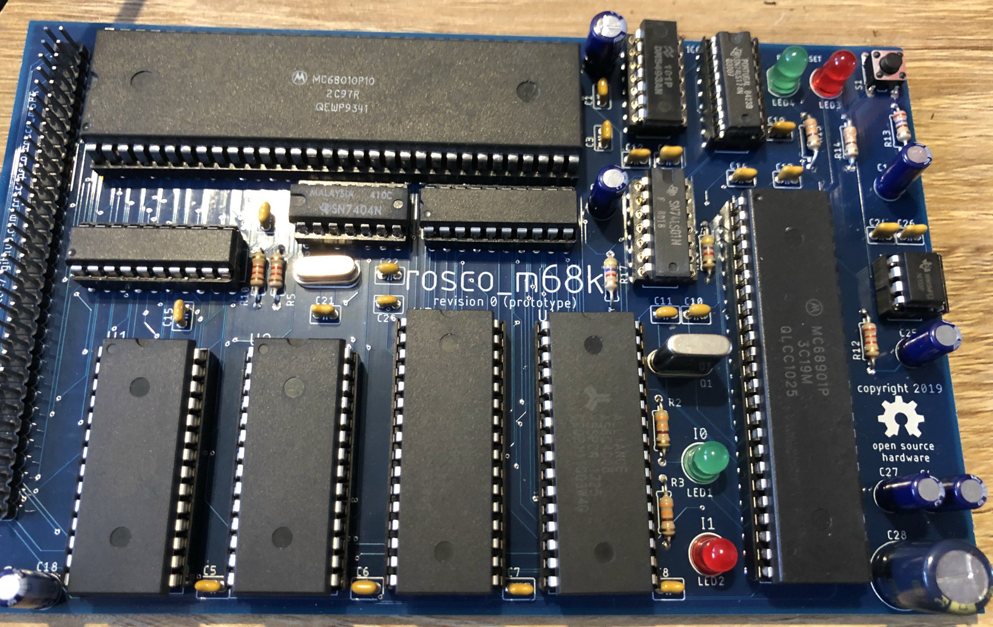
Oh, and before I go, here's how the revision 1 looks when populated and working:
![]()
With this revision of the main board done, I'm turning my attention to peripherals. I already have a couple of graphics chips to play with and have ordered a few bits for experimenting with mass storage too, so watch this space for lots more development to come!
-
Revision 1 PCB is out for manufacturing
03/17/2020 at 22:20 • 0 commentsJust a quick update to the previous log in which I talked about having made a start on the revision one design: I've now finished it and sent if off to the fab!
This revision includes a bunch of improvements, including:
- An improved expansion connector with support for MC6800 (legacy) peripherals
- A new IO and panel connector with GPIOs, software controlled timers and dedicated blinkenlight pins
- Doubled clock rate for the UART (allowing up to 9600 baud in the super-reliable divide-by-16 mode, or 115200 in fundamental, though YMMV here).
- Improved board layout (both in terms of place and route)
- Fixes for some silly mistakes in revision zero
This incorporates a number of suggestions made here in the discussion, so thanks to @Ken Yap and @henk.gooijen for those (not all of the suggestions made it into this revision but they're not forgotten!) and also to @paulvdh who took the time to help me import the project into KiCad and get started with it - I'm absolutely hooked now, and hardly miss EAGLE at all!
The new boards should be here next week (global pandemic permitting), I'll update when they arrive!
As always, the updated design is on GitHub: https://github.com/roscopeco/rosco_m68k/tree/master/design/r1
![]()
-
A brief software update
03/15/2020 at 22:17 • 0 commentsI've spent a fair bit of time on the software for the board over the past week, and finally have a fairly nice serial boot loader working, meaning that software iteration is now much quicker as there's no need to pull the ROMs and reprogram for each test. This also means fewer dead ROM chips (I've got a small collection of failed chips that haven't survived the constant pull/program/reinsert loops).
This boot loader also handles initialisation of the rest of the system and provides a few TRAPs that can be used by loaded code. These are leveraged by a very simple proof-of-concept "kernel" that can be loaded by the boot loader and handles relocating itself from the initial bootload location, C linkage (with .bss initialisation etc) and provides the beginnings of a low-level library that interfaces with the machine via the aforementioned TRAP vectors.
As well as proving the boot loader works, this will serve as a useful base-project for code that can be loaded by the loader, and means I can really start working on the software for the computer now I'm free of the the 16KB limit imposed by the ROMs.
So with that, the PCB migration KiCad done and work started on the revision one board, it's been quite a busy week all round :)
EDIT: Adding a link to the code in case anyone wants to have a look: the serial boot loader is here, and the POC "kernel" is here.
-
This is now an EAGLE-free zone!
03/15/2020 at 21:47 • 0 commentsI've mentioned before that I was unhappy with the way Autodesk now do licensing for their EAGLE CAD package, and that I wanted to move to something else (probably KiCad). No sooner had I mentioned this than the community said it could be done with relative ease, and @paulvdh supplied me with a conversion of the project as proof.
Unfortunately I've had a few issues getting KiCad to work reliably on macOS Catalina, but I finally got it working perfectly and spent some time getting to know it, and I have to say I'm very impressed. I was a little apprehensive about "unlearning" everything I know from EAGLE and learning a new package, but it's actually been pretty straightforward. Having a pre-converted schematic I knew well has probably been a huge help :)
I've now committed the conversion of the revision zero board to Git, and have made a good start on the revision one PCB. I started by working out the kinks in the converted schematic (for example, removing the control bus in favour of global labels since KiCad doesn't currently supported buses made of named signals) and now have a schematic and PCB that pass both ERC and DRC with zero warnings or errors, which I've committed as the initial work on the revision one board.
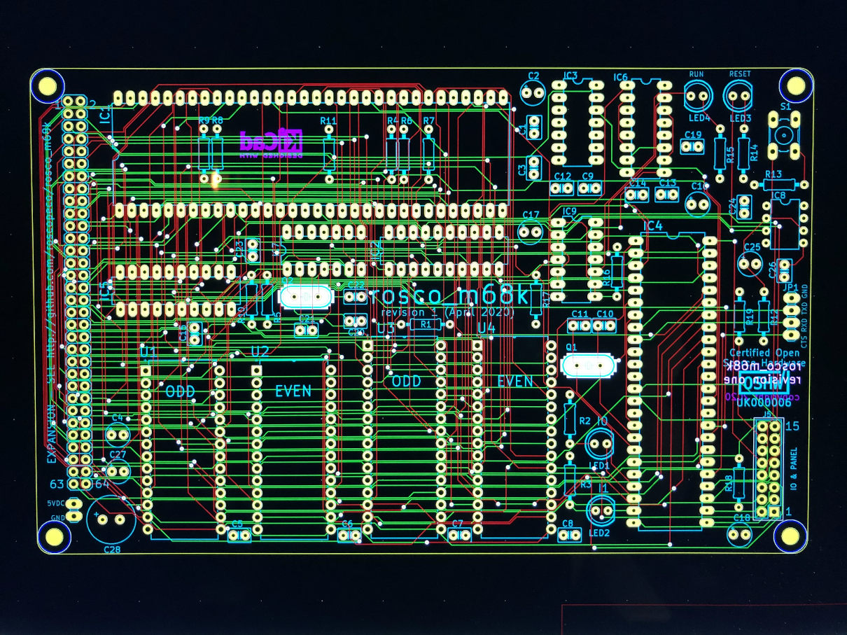
After tidying up a few text-size and placement issues on the PCB and fixing some of the schematic component footprints, the revision one is looking like this:
![]()
(I've also fixed the issues I raised against the r0 board at this point).
The EAGLE files have now been consigned to (git) history - and it feels good to be using a completely open-source toolchain for the design of the project, without all the artificial limitations that EAGLE standard imposed.
-
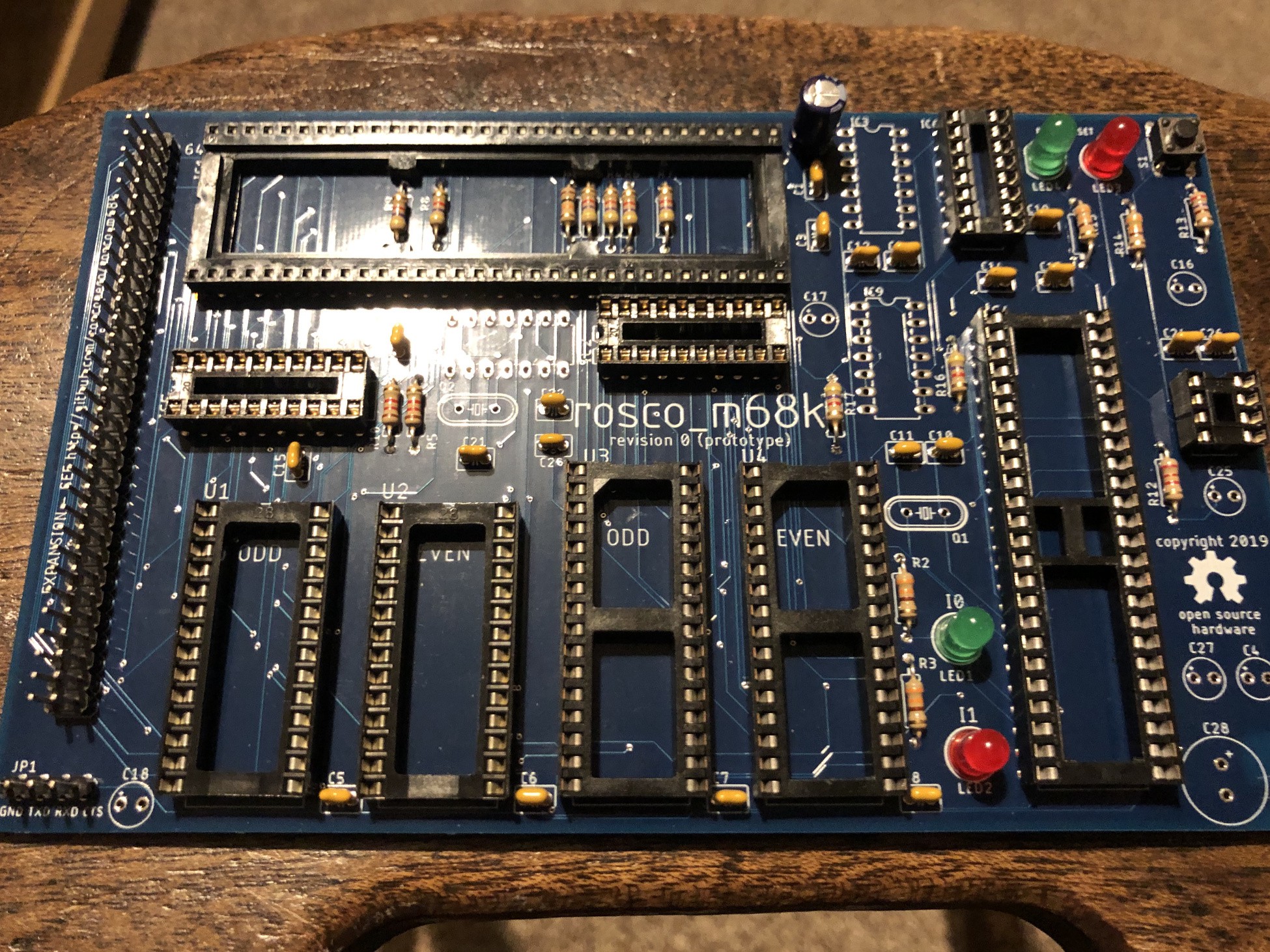
Revision 0 - PCB Population & Debugging
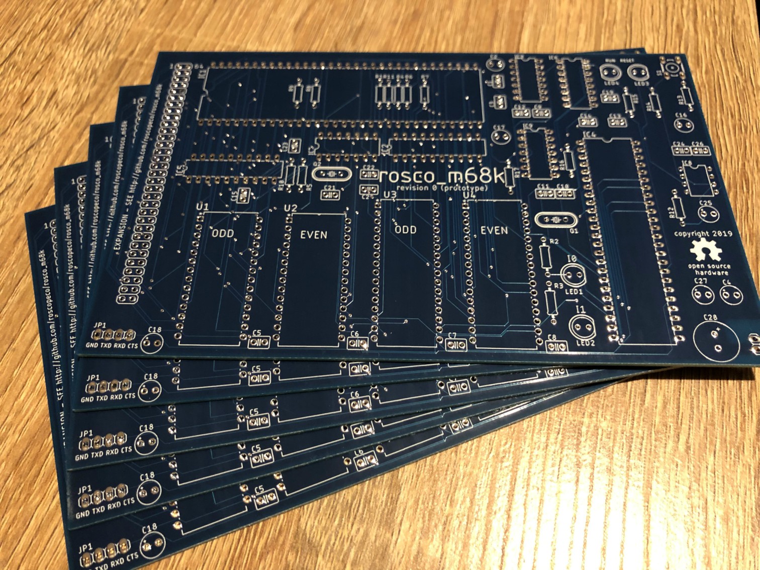
03/01/2020 at 13:40 • 2 commentsAs I mentioned in the previous log, the revision zero PCBs arrived last week, and I finally had time to source the final few parts I was missing (a few IC sockets) and solder up the boards. I wanted to socket all the chips for this first population in order to have fewer variables when it came to checking if the board actually worked (i.e. it would eliminate the possibility of me blowing an IC through ham-fisted soldering - I've even socketed the 555!)
I'm pleased to say that, a few minor issues aside, the board works perfectly, and is happily running the same firmware and test code that runs on the breadboard. The PCBs from JLCPCB are fantastic and lead-free hand-soldering was a breeze, even with the small clearances on a few of the vias I talked about previously.
The finished board looks like this:
![]()
I still haven't been able to get hold of any 74LS93s (they're in-transit from China) so I've substituted with a DM5493 I picked up as surplus from a local electronics store, and of course it works fine.
---------- more ----------In terms of problems, there were two - one simple, and one slightly less so. The first is that, when I designed the board, I envisaged using 64-pin DIL sockets with a single brace (aside: is there an actual term for these things?) halfway along, but in reality I wasn't able to get such a thing, and instead got sockets with two braces, at 1/3 and 2/3 of the length. This wouldn't be a problem except for the fact I've stashed some pull-up resistors under the IC, and the placement of them was exactly wrong for this type of socket.
This wasn't a huge thing, I simply cut the braces out - once the socket is soldered it should be strong enough without them, as long as a bit of care is taken when inserting the chip. You can clearly see this hack before the chip is inserted (at the top of the image), but it's neatly hidden once the CPU is in place:
![]()
The second problem took a little debugging, but I finally figured it out in the small hours of Sunday morning. I had to hook up the logic analyser, and wire to the LED panel I used for the breadboard build so I could watch what the address decoder was doing:
![]()
By this point I'd narrowed down the problem to something 68901-related, as the traces from the CPU all seemed fine - it wasn't wandering off into random memory, or getting stuck waiting for DTACK - it was definitely working, I just wasn't sure on what as the serial output was dead and the two indicator LEDs weren't working at all.
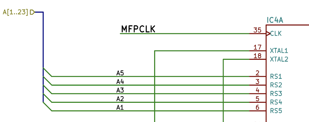
Through some debugging of the MFP (basically making sure it was being selected, was generating its own DTACK signal properly, and that this was being treated correctly by the glue logic) I tracked the problem down to a silly mistake in the schematic:
![]()
Yep - I've connected the register select lines of the 68901 to the address bus backwards... Cue massive facepalm, but happily this is an issue that can be worked around in software (by simply reversing the bits 1-5 in the MFP register addresses) so not a major problem. I raised a ticket to fix it properly, and did the workaround locally to continue with the testing.
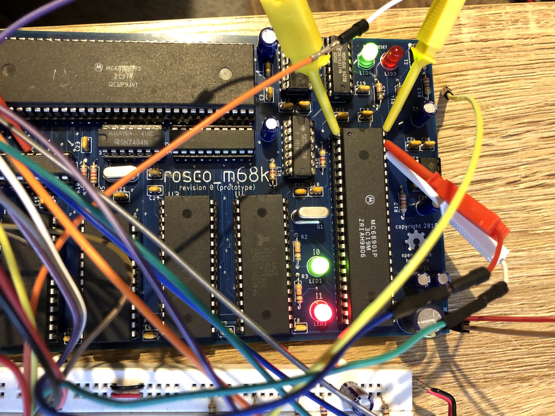
With that done, the board is working perfectly, as can be seen from the two indicator LEDs in the image below - this is running some test code that lights I0 once the memory test is complete, then lights I1 and flashes it once the MFP is fully initialised and interrupts are enabled.
![]()
And just like that, the project's breadboard days are over! I'll miss the breadboard, and I feel kind-of bad about tearing it down, but I've already had to steal a few parts from it (due to ongoing shipping issues thanks in part to Coronavirus), and I definitely won't miss the occasional blips when it just stopped working due to loose connections etc.
Oh, and debugging is much more convenient with the smaller PCB and its expansion connector, too...
-
Revision 0 PCB - Arrived!
02/26/2020 at 19:35 • 0 commentsFurther to the previous log, the revision zero PCBs arrived today, and I have to say I'm really happy with them.
![]()
As I expected, I immediately noticed a couple of things that I somehow missed during the design and checking stage, such as the right-angled trace under the odd ROM chip, and a couple of vias that are quite close to pads (pin 24 of the MC68901 at bottom right, for example), but I think I'll be able to work with it. I'm a bit annoyed with myself for missing these before sending the board for manufacture, but lesson learned for next time...
Speaking of next time, I talked previously about how I was looking at switching from EAGLE to something else, and no sooner had I said that than the awesome @paulvdh stepped in and spent some time proving that KiCad could not only import the EAGLE project, but could do it with minimal manual work. Just that would have been amazing, but Paul then went on to do lots of tidying up and fixing up of inconsistencies and finally made a bunch of comments explaining the work done and the differences between EAGLE and KiCad, so I'm now all set to start really getting to grips with KiCad. I really can't express how grateful I am to Paul for taking the time.
-
Revision 0 PCB - Possibly on its way!
02/23/2020 at 18:30 • 3 commentsFor the past few weeks I've been waiting for the revision 0 PCBs, and I was going to wait until they arrived before posting a log detailing the build, but I'm aware it's been a while and thought I'd do a brief update.
I eventually decided to do a trial order with JLCPCB - despite my initial leaning toward OSHPark the price was ultimately the deciding factor - for prototype boards it just made sense to go with China where I could get five-off of the r0 board for a quarter of the price I'd pay for three from the US. I've heard (read) good things about JLCPCB so I decided to give them a go.
Unfortunately, my timing was (as usual) terrible, and the boards have been waiting for production for over a month - the recent Coronavirus outbreak has really hit hard and nothing's been in production. They did re-start production on two-layer boards a couple of weeks ago, but my four-layer has been waiting for things to settle down.
Naturally, I've been checking on the order frequently, and just now I've noticed that it seems to be progressing! Apparently it's now "waiting for carrier to pick up", so fingers crossed it is actually produced and will be here soon! I'll obviously update as soon as I know more.
In other news, I've started looking toward a revision 1 design, with some changes I wanted to make and some awesome suggestions from @henk.gooijen (see the discussion for details - they're worth a look!). Sadly, I've fallen foul of the latest Autodesk debacle, as I cancelled my EAGLE standard subscription (with my typical terrible timing again) just before they stopped offering it as a standalone subscription. Now, if I want EAGLE standard again, I have to pay for Fusion 360 as well! This means that the price is now roughly four times what I used to pay, because they bundle it with a piece of software I neither want nor need.
So, I've been looking around for an alternative. I'm prepared to put up with a learning curve, and my needs are fairly modest:
- Must work nicely on macOS Catalina
- Must be able to import the EAGLE schematic for the project, ideally without manual fixes
- Ideally would be able to import the EAGLE board with minimal manual fixes
- Must be reasonably priced!
- Must support four-layer boards of 160x100 (and ideally more layers/space)
I've had a look at KiCad in the past, and that seemed the most likely candidate, but I've not been able to get it working reliably on Catalina yet. This is something that I think is being worked on, so it will probably be the way I go - and to be honest, I've always felt I should be using it anyway, rather than the proprietary EAGLE...
In the meantime, if anyone has any suggestions for other software I might try, I'd love to hear about it!
-
Plans for 2020, and OSHWA certification
12/31/2019 at 14:23 • 0 commentsWow, it's been a bit quiet here since August, and for that I apologise. I've been very busy with work and family commitments and haven't had much time to spend on any of my personal projects. However, as we move into 2020 I'm planning to ramp it back up!
In no particular order, this is what's on the agenda next year:
- Finally getting the r0 boards populated (more on that in an upcoming log)
- Working in some fixes and changes (many of which were suggested down in the comments, thanks @henk.gooijen and others!) for a revision 1 of the board.
- Tidying up the Zmodem firmware I've been working on and getting it committed to github (Again, there's another log in the pipeline for this!)
Generally speaking, what I'm hoping to achieve in 2020 is having a small offering of bare boards and possibly kits for this project at a very reasonable price. The kits would of course included pre-programmed PLDs and ROMs.
In the meantime, the project is now OSHWA certified (number six in the UK). Although the project has always been open-source hardware, and has the open-gear icon, that is very much self-certification - the OSHWA certification is recognition that the project fits with wider-community definitions of open hardware, and I'm looking forward to putting the mark on the revision one board!
![]()
rosco_m68k
A full-featured Motorola 68k retro computer, starring a 68010 running at 10MHz