Ross Bamford
-
Serial Now Fully Working!
08/27/2019 at 19:01 • 0 commentsAs I mentioned previously, I have been having some odd problems getting the serial receive working on the MC68901. No matter what I tried, it just wouldn't work. I went into some detail in the previous log about the lengths I'd gone to to try and fix this, so I won't reiterate here. I'll just say new MC68901's I ordered from China finally arrived today, and everything now works perfectly.
Turns out my suspicion about the SI pin (or possibly RC I guess) being dead on my original 68901 was spot on, and I'm not going crazy after all.
So onward with the PCB fab! Oh, and on that note, I've just finished documenting the new board's expansion connector on Github - have a look if pinouts are your thing.
-
Another PLD and (finally) a PCB!
08/23/2019 at 18:39 • 0 commentsExciting times ahead! I've spent the last couple of days tidying up the schematic and finally made a start on a PCB design in Eagle. It turns out that PCB design is hard, but I've pushed on with it, learnt a lot, and started over at least four times (ripup ; has been a go-to command). I've used the autorouter to help me see where component placement was sub-optimal, and then I've moved things around and tried again. I wish I could say I'd hand-routed everything but I've definitely had help from the autorouter - I let it get me started and then spent many hours redoing its craziness. So I guess the final board is a kind-of collaboration between me and the autorouter...
One thing I found early on was that the board was just too full to allow sane routing. There were still eight 7400-series chips on there when I started, so I decided it was time to put some more of the glue logic onto an ATF16V8BQL. I wrote another bit of CUPL code to handle more of the glue logic. The code looks like this (pin declarations etc omitted, full code here):
IACK         = FC0 & FC1 & FC2;
DTACK        = !IACK & ((IOSEL & MFPDTACK) # EVENROMSEL # ODDROMSEL # EVENRAMSEL # ODDRAMSEL );
MFPDS        = LDS # IACK;
RAMOE        = RW;
And just like that, four 7400-series ICs were removed from the schematic. Obviously I tested it first on the breadboard before I tore down the old circuits, but it works like a charm.
That done, the routing was made a bit easier, but (being cheap) I was still trying to do everything on a two-layer board. I quickly gave up on that though (I think after the third ripup;) and switched to a four-layer design with power and ground planes. Sure it's upped the cost (OSHPark are quoting me USD 248 for three boards vs $124 for three two-layer boards) but it's worth it, both from the routing point of view and the electrical one - I'm confident I won't have any issues with burnt out traces or grounding issues.
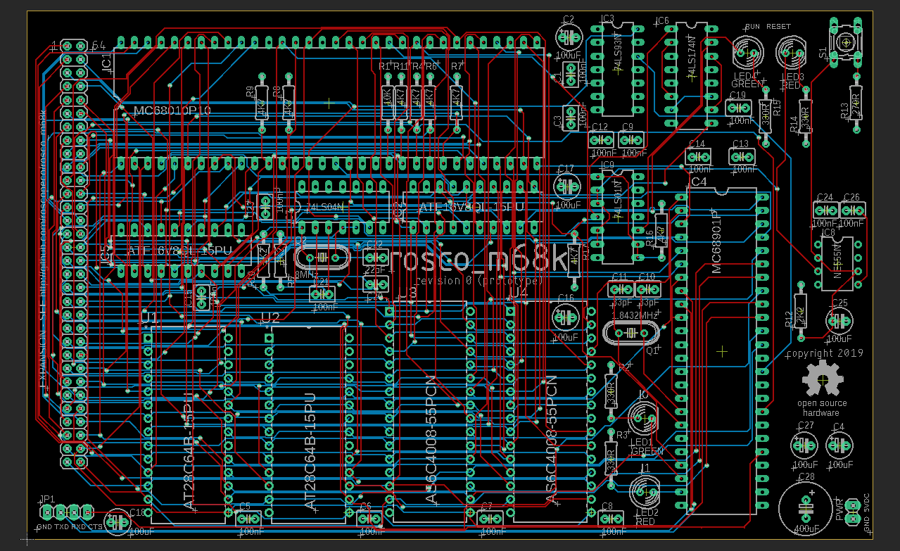
This is the board as it currently looks (Layers 2, 15 and bNames omitted for clarity):
![]()
It's by no means perfect (I'm still a n00b remember) and probably isn't done at this point, but it passes all the electrical and design rule checks (with OSHPark's rules included) and I'm reasonably confident it will work, so I'm going to go ahead and order three as prototypes and see how it goes.
Before I do that though, I'm waiting on those replacement 68901's to arrive, because depending on whether they fix the problem or not I may have to do a bit more work on the design - if so I'll update the board before I send it off for manufacturing.
As usual, all of this is now merged into master and available on Github. You'll also find updated schematics there (also as a PDF if you're not an Eagle user) and an updated BOM.
-
All new schematics and BOM
08/14/2019 at 21:24 • 0 commentsAs I mentioned before, I'm starting to look toward the day when this project will produce a PCB, and I've spent some time today taking a big step toward that - putting all the schematics together properly in Eagle, sorting out the IC count a bit more by using previously-unused gates where possible, and getting it to dump a prelimimary BOM.
To keep things sane, this has meant I've had to move to more than two schematic sheets. Unfortunately, that means that the schematic is no longer compatible with the free version of Eagle. While this is unfortunate, I've mitigated it somewhat by checking in (to git) the schematic as a PDF and dumping the BOM in text format. I'll keep these up to date whenever I change the source schematic, so anyone wanting to use the schematic can still access it without having to have a paid copy of Eagle.
I will admit to agonising a bit over this decision, and considered switching to a different CAD package (e.g. KiCad) but the reality is I don't know them, and I do know Eagle pretty well, so switching at this point wasn't really viable.
As always the designs are on Github. The PDF schematic can be found here, and the BOM is here. The old (obsolete) schematics are still available here.
This is a major step toward getting a PCB designed and fabbed (there's been talk of that being an Anglo-Aussie collaboration which would be awesome) and I'm pretty pleased with the results.
(In other news, I've not given up on the serial input issue I talked about in my last log. I've hacked on it a little more and gotten to the point where I need to rule out a problem with the MC68901 itself, so I've ordered five more which should be here in a week or two).
-
(Not) Receiving Serial Data
08/12/2019 at 20:28 • 0 commentsI've grown tired of pulling the ROMs for programming every time I want to try something in the firmware, and having managed to kill one of the ROM chips while doing so (ESD I guess) I decided the time was right to hook up the 68901's Serial In line to the cp2102's TX line so I could hook up a simple Zmodem implementation, allowing me to send code to the running board via the serial link. The idea behind this is to allow me to more quickly iterate on the firmware that will eventually interface with mass storage devices and such.
Unfortunately, having been at it now for a couple of days, I just don't seem to be able to get it to work. No matter what I do, the 68901 just doesn't respond at all to input.
To begin with I built the new code into the async serial driver and set it up so that the whole thing would be interrupt driven (by the RX Error and RX Buffer Full vectors), but it didn't work. The interrupts were never generated.
(As a side note, in the course of doing this I did come across a bug in the serial transmit code that caused it to silently die after the first time the ring buffer becomes completely empty, which is now fixed, so that's something at least).
For sanity, I went back to basics and wrote a simple 'echo' program in pure assembler that didn't bother with the interrupts at all, and just did polling on the RX Buffer Full and TX Buffer Empty. Still nothing - the MFP never sets the buffer full flag.
Getting desperate, I hooked up the probe to the SI line and ran a few-seconds of trace while I pressed keys in minicom, and sure enough the UART decoder in PulseView showed the data was getting there just fine. I did this because I was worried that Minicom's hardware flow control might be causing problems, even though I have the cp2102's CTS line grounded right now (eventually I'll drive it from one of the MFPs GPIO lines but for testing grounding it should be just fine).
I tried lowering the baud rate (all the way down to 4800), switching from the fundamental clock mode to the divide-by-16 mode (which I know can make a difference to receivers), and finally I decided to port someone else's code (actually, the monitor program from the awesome Rhombus project: https://hackaday.io/project/8725-rhombus) to my board, in the hope that their working code would show me what I was doing wrong.
This isn't a perfect test as I've had to make some changes to the MFP initialisation code (my clocks are different frequencies to Rhombus and I don't have any compatible crystals at the moment) but I've only changed the timer frequencies and switched from using two timers on the MFP to just having one timer driving both TX and RX clocks, which is the way my hardware is set up (as I write this, I'm wondering if/how that might be the cause of the problem...?).
Anyway, to cut a long story short, it doesn't work, in exactly the same way that my own code doesn't work. Right now, I don't have any idea why.
I'm going to take a break from this tonight, and hopefully have fresh ideas tomorrow. In the meantime, if anyone's got any ideas or suggestions I'd love to hear them - hit me up in the comments :)
-
New Address Decoder is in!
08/03/2019 at 20:11 • 8 commentsIn my last log, I talked about how I was getting started with PLDs in hopes of replacing the 7400-series chips that made up my address decoder. I'm pleased to report that I refined the CUPL code for the ATF16V8B I'd bought, and the chip is now on the board and working perfectly.
This has brought multiple wins to the project - I've saved a fair bit of board space (8 7400-series have been removed) so the eventual PCB fab will be cheaper, power requirements are lessened, and I've finally been able to fix some bugs in the original decoder design (e.g. gating everything off with /AS and /IACK meaning less additional support circuitry is needed). This also means that /EXPSEL now works as I originally intended.
The rough CUPL code I posted last time has been considerably cleaned up (it was originally a dump from Logisim's combinatorial analysis). The main logic for the six output pins looks like this:
!EVENRAMSEL  = IACK & BOOT & !UDS & !A23 & !A22 & !A21 & !A20;
!ODDRAMSEL   = IACK & BOOT & !LDS & !A23 & !A22 & !A21 & !A20;

!EVENROMSEL = IACK & ((A18 & A19 & A20 & A21 & A22 & A23) # !BOOT) & !UDS;
!ODDROMSEL  = IACK & ((A18 & A19 & A20 & A21 & A22 & A23) # !BOOT) & !LDS;

!IOSEL      = IACK & !A18 & A20 & A21 & A22 & A23;

!EXPSEL     = IACK & ((!A20 & A23) # (!A20 & A22) # (A21 & !A22) #
              (A21 & !A23) # (A20 & !A21) # (A18 & !A19 & A20));
It's probably still not perfect and could maybe be made more simple, but it does the job and is a big improvement on the previous code.
I can't overstate how much this has improved things - before I tore down the old decoder I spent some time running traces of the old select lines vs the new, and it was startling - the old one was fast enough but with the new one, there is virtually no delay between the input and output. I'm pretty sure I could take the system up from 8MHz now to the CPU's rated 10 with no problems. I could probably even overclock to 12MHz and things would still be fine - the limiting factor now is the ROM (which is already nearly maxed out).
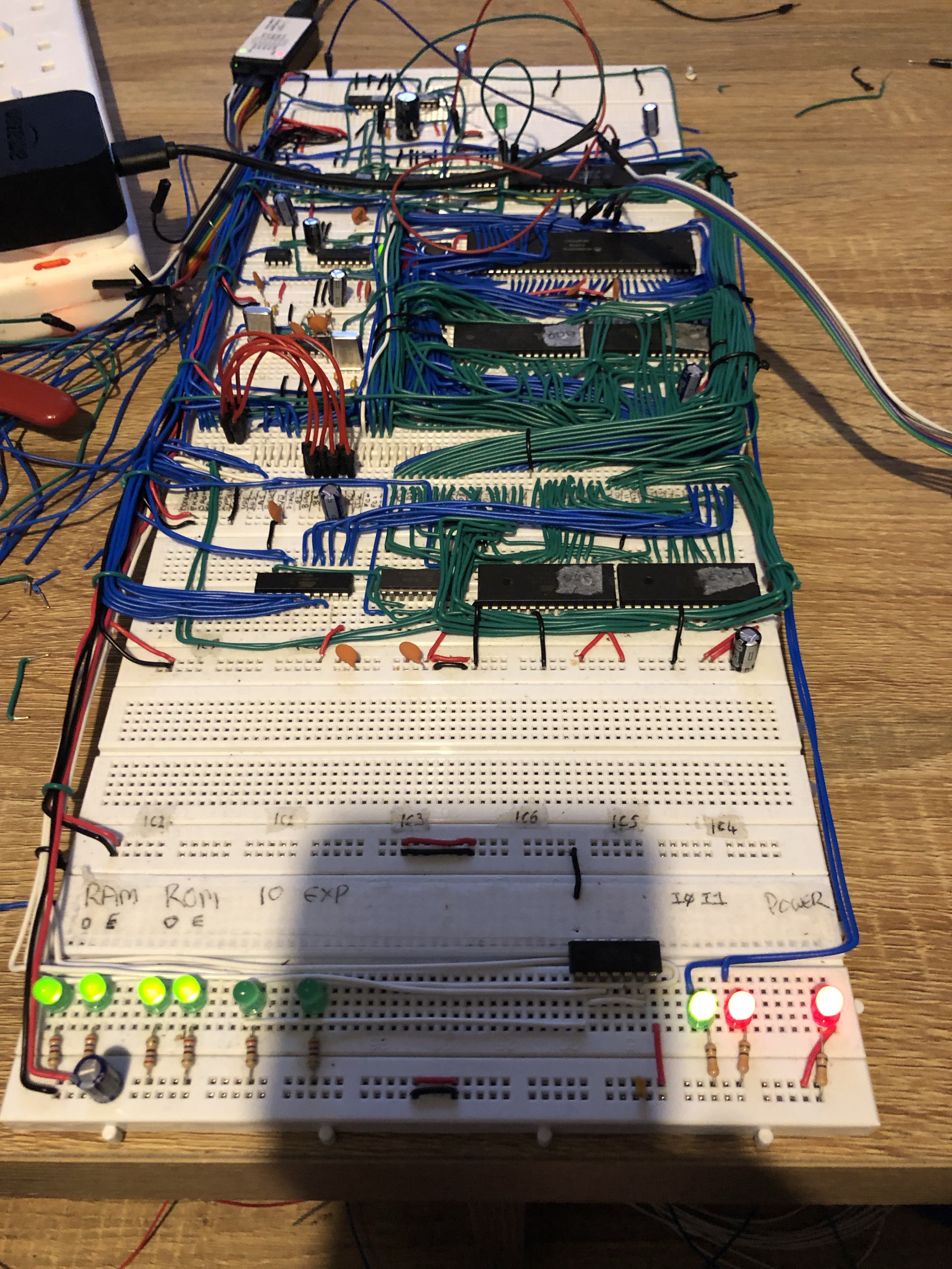
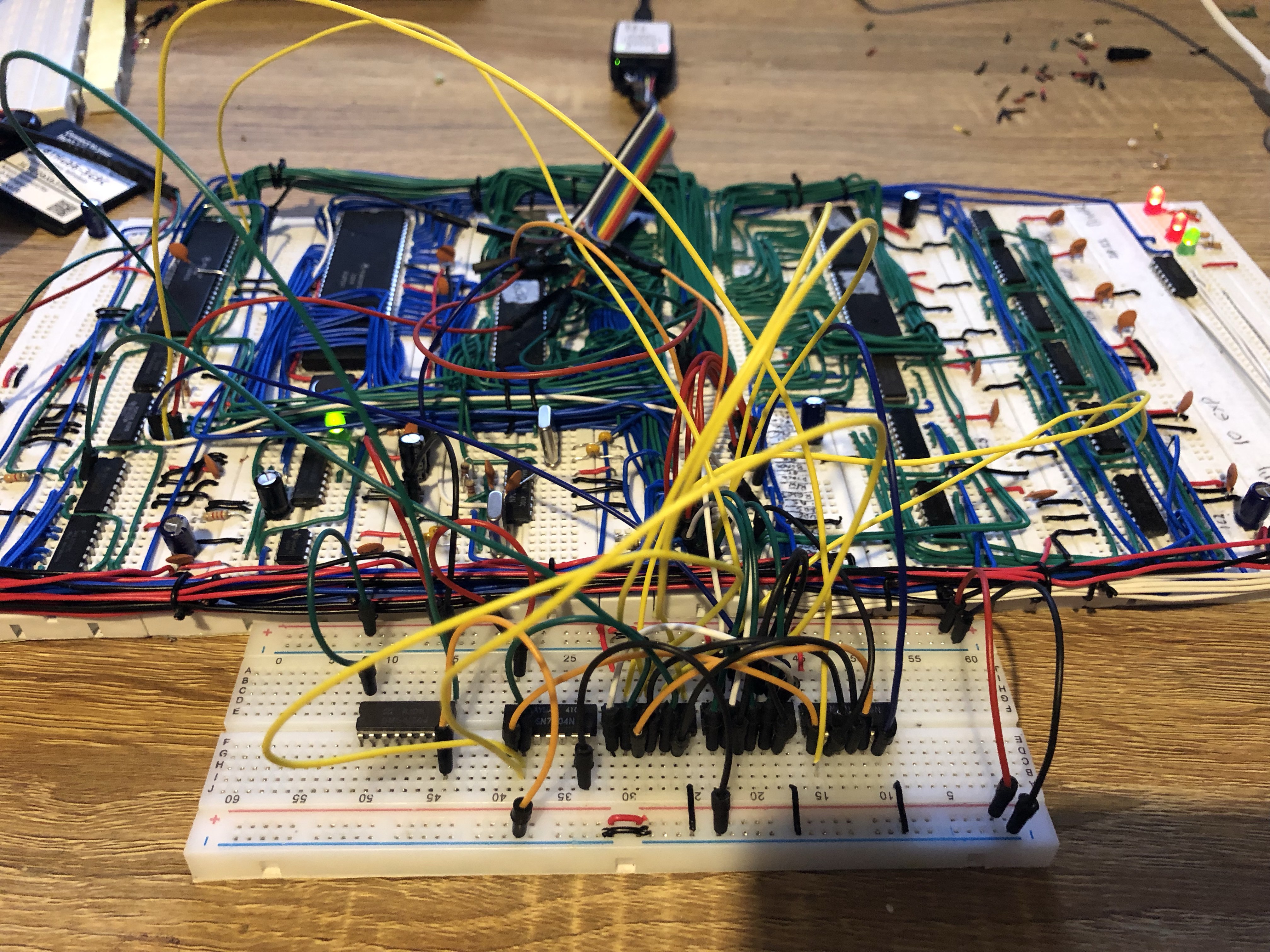
The board now looks like this:
![]()
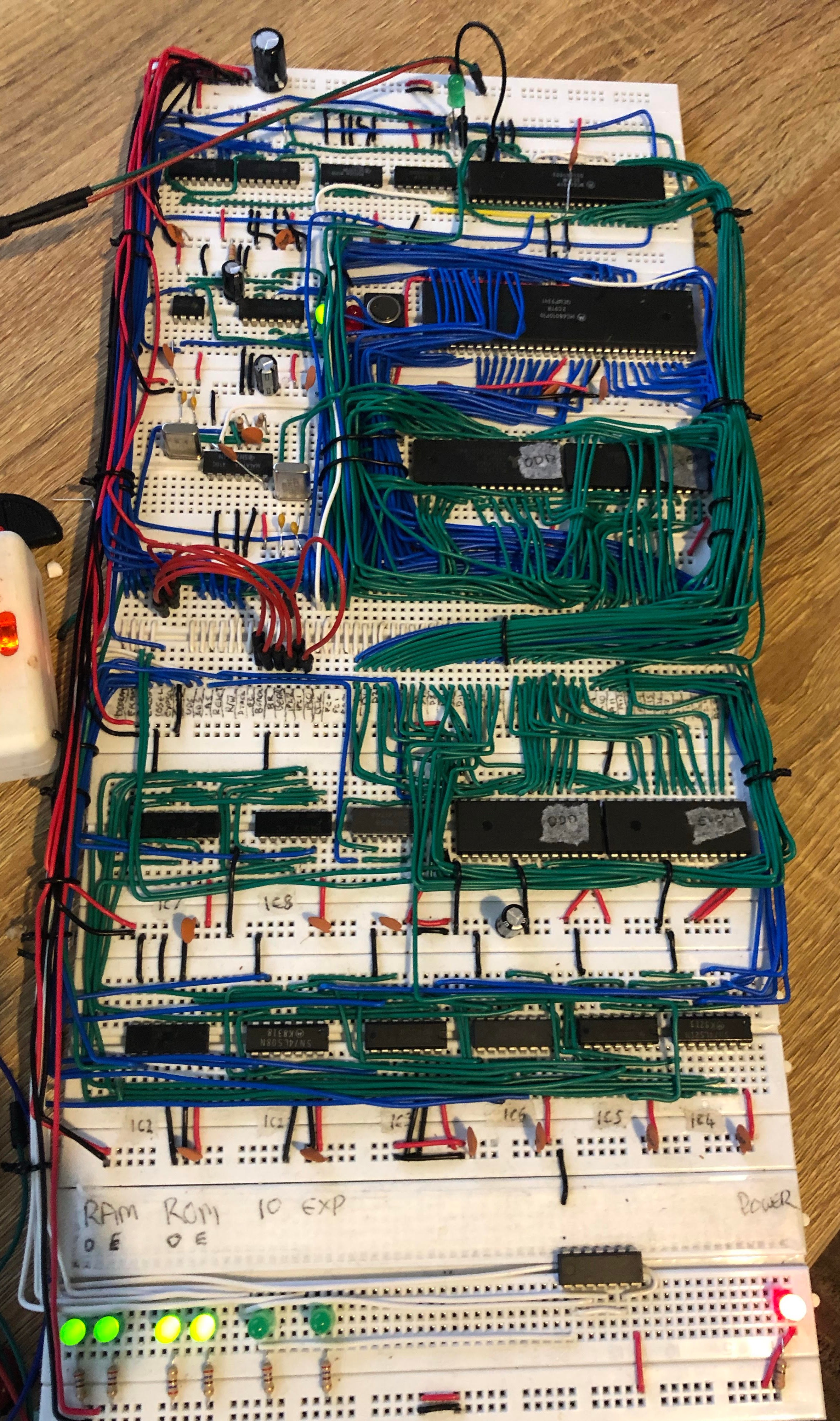
The new decoder is to the left of the ROMS. The wide open spaces to the left and below it are where the old address decoder used to live. For comparison, here's an older iteration of the board with the decoder (and it's copious wiring) still in place:
![]()
As per usual, all the code for the PLD is available (along with all the designs and code) on github.
-
First steps with programmable logic devices
07/15/2019 at 19:04 • 3 commentsI'm starting to become really nervous about the breadboard-based nature of the project as it grows and becomes more complex. This was really brought home to me a few weeks ago when I had to transport the board to work where I was demoing it to some interested colleagues - the transport went fine and the board made it there and back in one piece, but it was pretty nerve-wracking plugging it in a hoping it still worked!
For this reason, I've started to think about doing a PCB design with the board as it stands today. This would have expansion bus capabilities, allowing me to continue to design new bits (e.g. graphics) on breadboard, but would cement the working core of the computer onto a proper, reliable board.
Before I can do that though, I've decided to revisit some of my earlier decisions in light of this new plan - specifically, the address decoder and glue logic should probably be handled by programmable logic rather than discreet logic as they currently are.
The current design (with lots of 7400-series chips) works well, but is pretty power-hungry and takes up a lot of board space. Previously this didn't really matter, but if I'm now going to be spending $5-$10 per square inch of board space, I want to make sure I'm making the most of those inches. Replacing many of the fourteen 7400s with two or three PLDs makes a lot of sense now - it'll mean cheaper boards, and less soldering when the time comes to assemble them.
My reason for using discrete logic initially was for the learning experience, and I'm really glad I did it. I'm a lot more familiar with the 7400-series now, and have become used to designing circuits with them. I've found numerous uses for them in other projects too.
But going forward, it's time to cut the chip count. With that in mind, I've gotten hold of a bunch of Atmel ATF16V8BQL CPLDs, and started learning to use them (I've never done CPLDs before, so all good for more learning!)
My first stab has been the address decoder (CUPL code here - but go easy on me, this is my first time!) and, in basic testing, it seems to work exactly as it should. It even fixes a couple of bugs in the existing address decoder, including making the EXPANSIONSEL line work sanely and gating the whole thing off with the CPU's /AS line.
Even better, it now takes up one twenty-pin DIP rather than a whole bunch of 14-pin DIPs, and uses less power. I've not actually integrated it into the build yet so may find it doesn't work in some horrible way, but according to the datasheet it should be plenty fast enough (faster than the discreet logic design) and as I say in manual testing it seems to perform perfectly, so I'm not expecting any big surprises (I know, I know, famous last words...)
-
Async Serial Output
07/15/2019 at 18:46 • 0 commentsIt's been a few weeks since I've updated here as I've not had as much time to spend on the project as I'd like, but some progress has been made on the software side - I'm now using a proper toolchain for the firmware, consisting of GCC and VASM, so no more Easy68k weirdness to trip me up!
I've also fleshed out the Serial output via the MC68901 such that it is now completely interrupt driven. This replaces the polling it was doing previously. Whenever the software writes to the serial output, the data is placed into a ring buffer and the MC68901's vectored interrupts drive the actual output from there.
The serial driver is implemented partly in a mixture of C and assembly - the C code is here and the assembly is here. The top level directory for the firmware is here and contains all the code, the Make build, and bits and bobs like the linker script that ties everything together.
This was all done in a bit of a rush as I was giving a talk on the computer (and demoing it) at work so I wanted to have some level of sophistication. It's all since been cleaned up and is now pretty nice (in my opinion). The next step in the plan is to enable the RX serial line, and then put in a simple protocol (probably xmodem initially) to allow software to be uploaded via serial link, freeing me from the 16K ROM limit and allowing me to develop the OS without pulling the ROMS for programming every time I iterate :)
-
Vectored Interrupts are Now a Thing
06/18/2019 at 08:02 • 0 commentsIn my last log, I talked about how I was getting interrupts to work, but that I hadn't yet made them work properly. It appeared that, no matter what the interrupt source in the MFP it would always present $FF as the vector during IACK. This was especially strange because the vector base set in the MFP's VR register is $40, so where the $FF was coming from was a mystery.
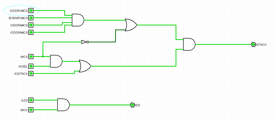
I suspected my DTACK generator wasn't robust enough as it didn't take IACK into account, so my first step was to redesign the DTACK generator to take that line into account. No EAGLE schematic yet but in Logisim the design looks like this:
![]()
This also adds in a way to generate the MFP's DS signal during IACK since the MC68010 doesn't appear to assert LDS during this time, and without DS the MFP won't generate DTACK.
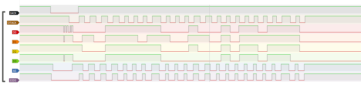
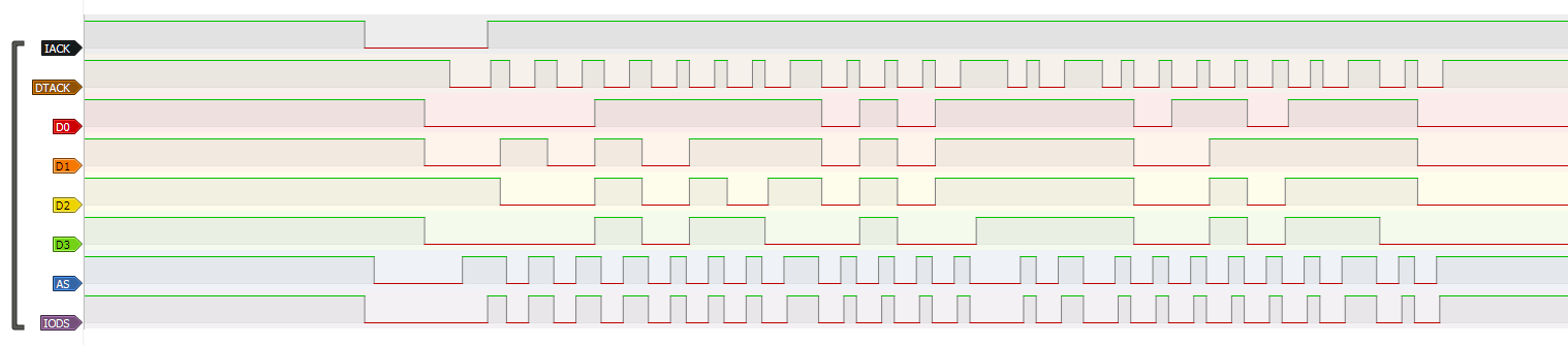
This improved things somewhat, but it still wasn't working. Breaking out the probe and looking at the data lines during IACK was telling:
![]()
A glance at the mess that is D0 (and to an extent D1 and D3) told me what the problem was - I know the bus doesn't float at this point (especially because it's still not stable after the MFP asserts DTACK), so this can only be contention.
Sure enough, further tracing revealed that, due to the design of the address decoder, the ROMCS lines also get asserted for a short while during an IACK cycle. This is because I didn't gate the address decoder off with anything which, while not exactly efficient, was good enough at the time. Gating it off with AS wouldn't help, as the CPU asserts AS during IACK. I realised I could gate it off with the inverted IACK signal from the new circuit from the shot above.
That looked much better:
![]()
Nice clean edges, and tracing all the data lines showed the MFP was putting 0100 0101 on the bus, which is $45, exactly the right vector for the MFPs Timer C interrupt.
A quick fix in the software to put the handler on vector $45, and all is working perfectly. Just need to tidy it up on the board and wire it up correctly, and I can move on to the software support for the interrupts. Currently it's just thrown together on an extra board, and looks like this:
![]()
-
System Timer Interrupt
06/16/2019 at 21:35 • 4 commentsNow I have the MC68901 MFP integrated and the UART is working, I spent a bit of time this weekend setting up Timer C of the MFP as a timer tick I can use in the OS for multitasking.
For testing purposes, I've set the timer up at about 18Hz and have the interrupt handler just flash an LED connected to MFP GPIO 0. That way, I can visually see that the handler is being run. The code that sets up the MFP now looks like this (I've also upped the UART to 19200 baud):
* Initialise MFP
*
* Trashes: D0
* Modifies: MFP Regs
INITMFP:
* GPIOs
    move.b  #$FF, MFP_DDR   ; All GPIOs are output

* Timer setup - Timer D controls serial clock, C is kernel tick
    move.b  #$00, MFP_TCDR  ; Timer C count is 0 (equivalent to 255) for 18Hz
    move.b  #$0C, MFP_TDDR  ; Timer D count is 12 for 19.2KHz
    move.b  #$71, MFP_TCDCR ; Enable timer C with /200 and D with /4 prescaler

* USART setup
    move.b  #$08, MFP_UCR   ; Fundamental clock, async, 8N1
    move.b  #$05, MFP_TSR   ; Set pin state high and enable transmitter

* Interrupt setup - Enable timer C interrupt for kernel tick
    move.l  #MFP_VECBASE, D0
    move.b  D0, MFP_VR
    or.b    #$20, MFP_IERB  ; Enable Timer C interrupt...
    move.b  #$20, MFP_IMRB  ; ... and unmask it.

    rts
The code for the handler is very simple:
TICK_HANDLER:
    bchg.b  #0, MFP_GPDR
    rte
Because I'm using vectored interrupts, this should be on vector 0x45 (MFP_VECBASE is 0x40 and Timer C is at offset 5 in the MFP), but because of a limitation of my IO DTACK generation it's not actually working that way - the IO DTACK circuit doesn't take account of /IACK and so /DTACK is immediately asserted, presumably before the MFP can put the vector on the bus. This causes the vector to always be FF, so for now the handler is just mapped there for testing.
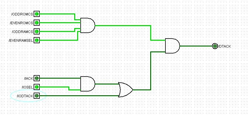
To actually fix this, I'll need to revisit the /IODTACK generator. I've not put anything down in EAGLE yet, but my plan is to build something like the following:
![]() Which is basically the same as it is now, with the addition of /IACK into the logic to cause it to work when the CPU is doing an acknowledge cycle.
Which is basically the same as it is now, with the addition of /IACK into the logic to cause it to work when the CPU is doing an acknowledge cycle.
There may be a bit more to it, as I'm not 100% sure at this point what the CPU does with /LDS during an acknowledge. The MFP needs its /DS to be asserted along with /IACK so I may need to do a bit more work there, but I'll know tomorrow when I've had chance to look again at interrupt acknowledge in the MC68010 manual. -
Hello, World!
06/09/2019 at 21:44 • 1 commentAfter a trying weekend working on the m68k build (see the previous two logs for details) I finally reached the "Hello, World" stage in the board's development. That's right, the UART is now working and integrated with the USB to TTL converter I'm using at the moment.
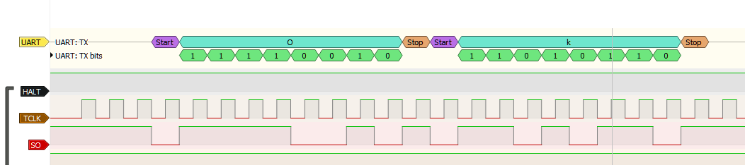
Once I'd worked out how to get the UART properly initialised, I hooked up the analyzer to the TCLK and SO lines of the 68901 and ran a simple bit of code that would just output "Ok". Here's the trace from that:
![]()
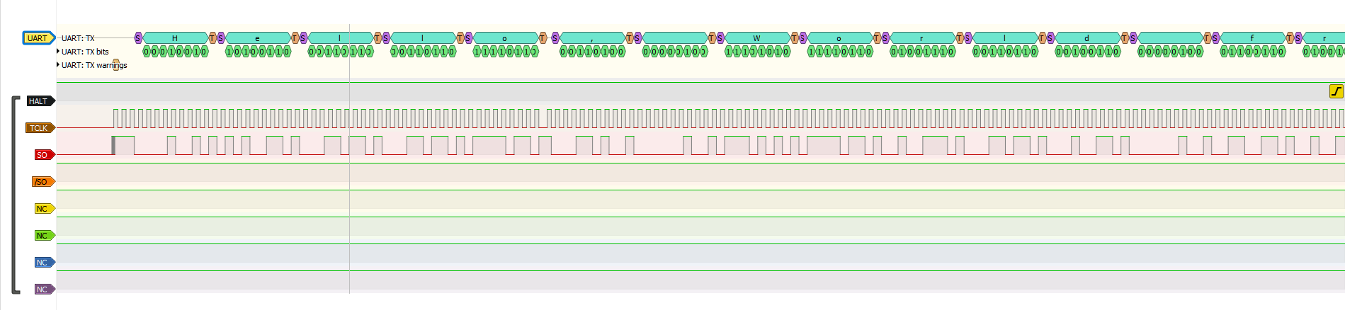
The "Ok" characters were moved into the UART data register as immediates. Expanding this to support sending out a null-terminated message exposed a wiring mistake in the board - it was the first time I'd done byte-sized reads from ROM space and it turned out I'd wired the chip selects backwards to the address decoder. With that fixed, I was able to output characters from a constant string in a loop:
![]()
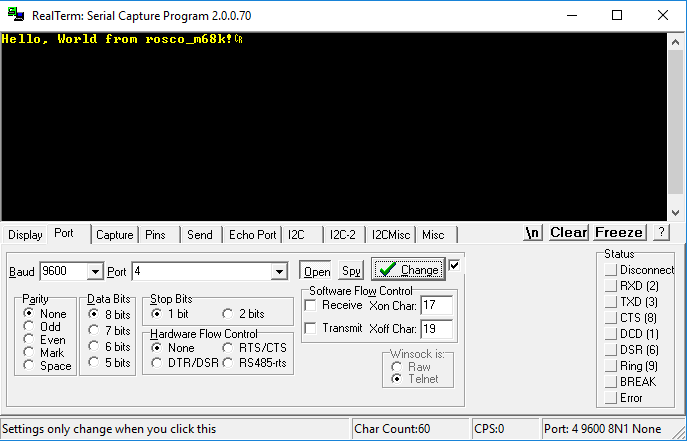
Finally, by hooking up the USB converter and plugging it in (to my Windows laptop as the cable is too short to reach my main machine), I was able to verify the results in a terminal:
![]()
And just like that, the rosco_m68k now has a way to do output. The challenges and annoyances of the weekend are forgiven - onward and upward!
rosco_m68k
A full-featured Motorola 68k retro computer, starring a 68010 running at 10MHz
 Which is basically the same as it is now, with the addition of /IACK into the logic to cause it to work when the CPU is doing an acknowledge cycle.