A few days back I played around with creating a siren sound on the Atmega328P, which I would later port to the Attiny85 and incorporate it in this project. I simply hooked up a piezo directly to one of the I/O pins (with a series resistor.) It worked just fine.
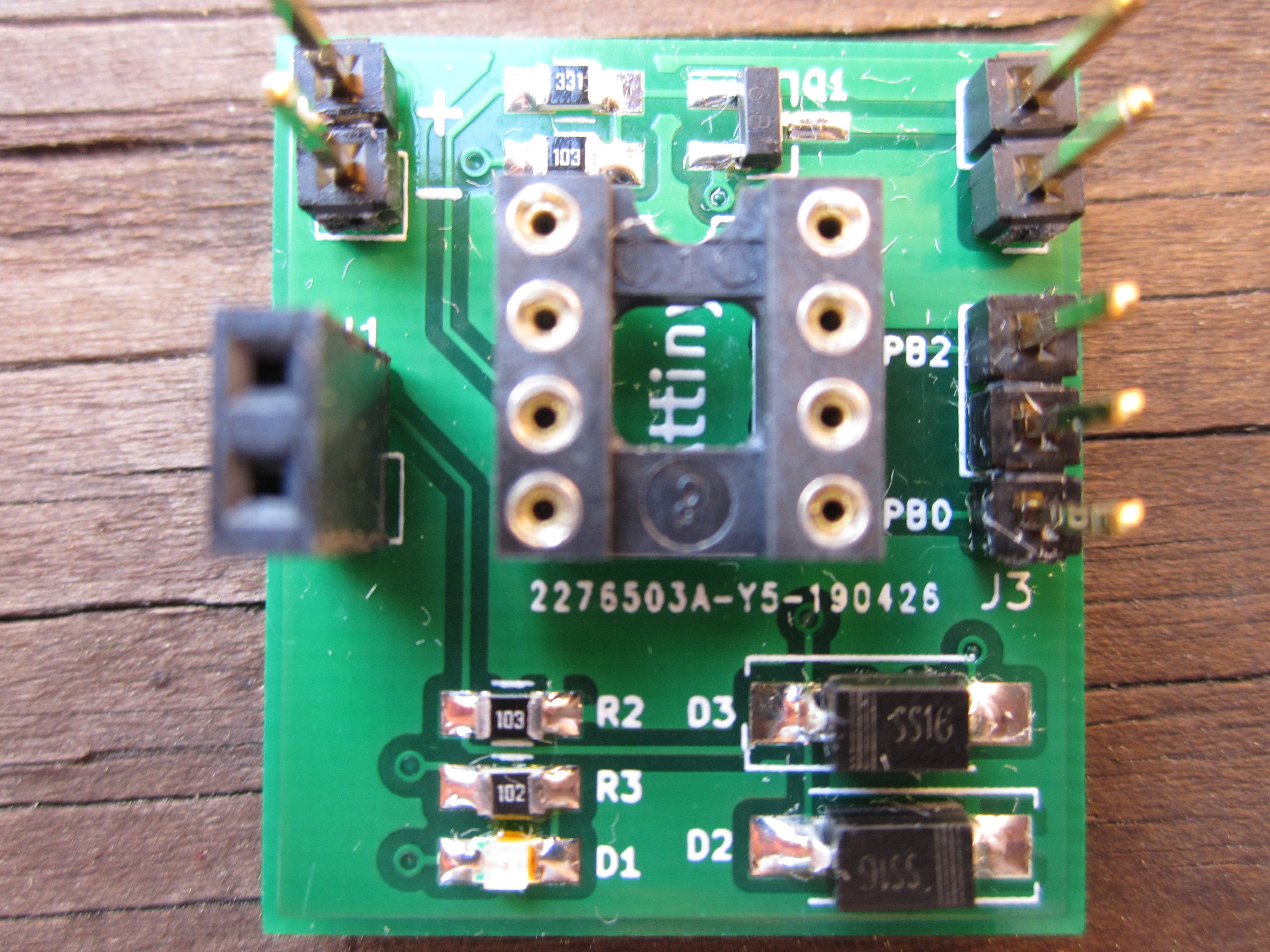
Yesterday I assembled one of my new Water Alert boards that I got last week. I ported the siren code over the the Attiny85 and plugged the programmed Attiny85 and a piezo into my Water Alert board.
I heard absolutely nothing.
I checked my code, found something that needed to be changed and tried again; nothing. I swapped the piezo for a larger one. This time I heard it extremely faintly. Some progress at least. I then went down the rabbit hole trying to isolate the problem. I went from using a 2xAA battery back to a 3xAA pack; no improvement. I hooked up the board to a 5V supply; no improvement. Could the issue be the cheapo "Shenzhen special" transistor on the board? I created a breadboard version of the peizo driver circuit and once again, no improvement.
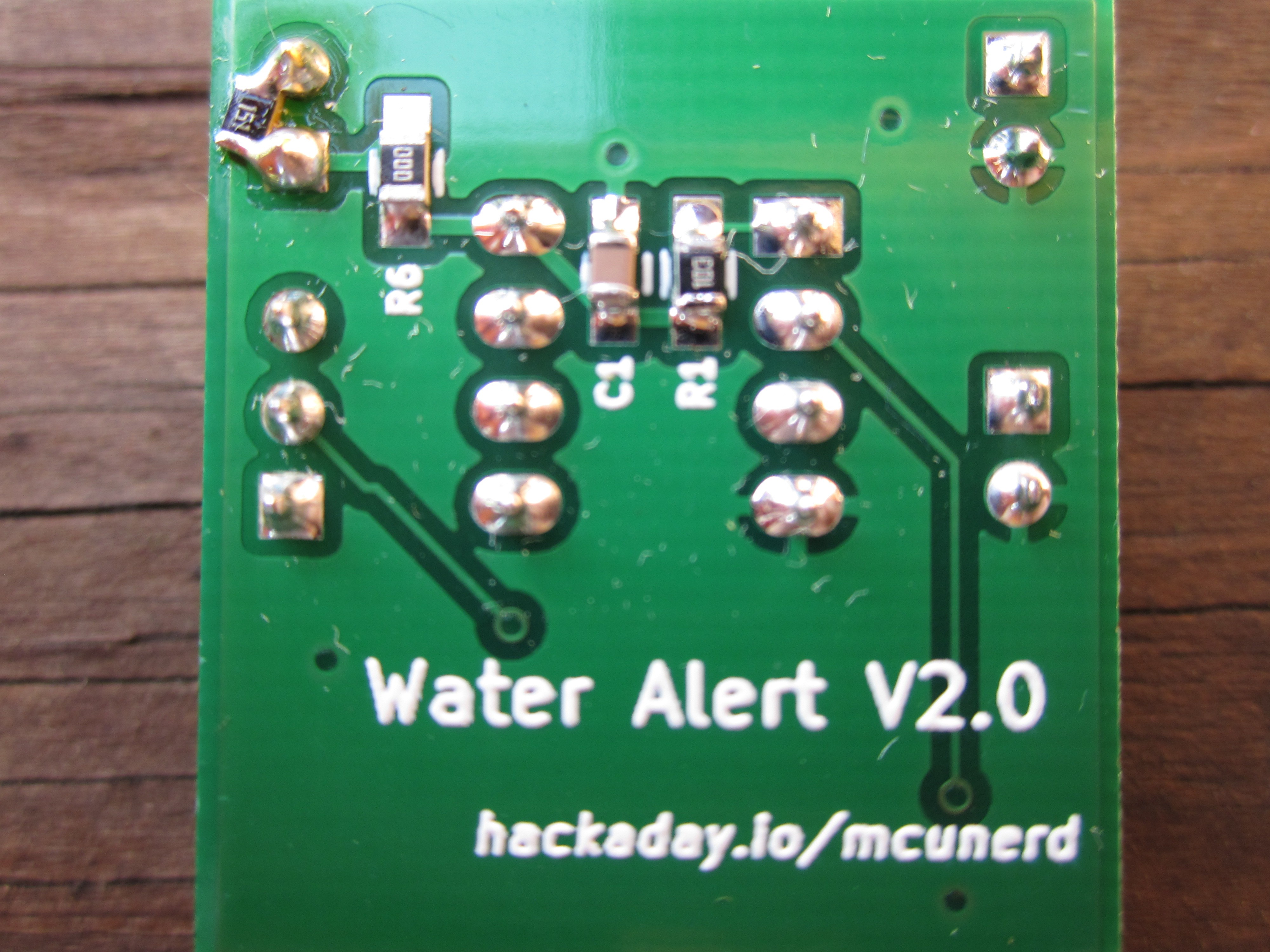
I decided to try directly driving the piezo from the I/O pin. A considerable improvement occurred. Perhaps the issue was how I was trying to drive it. I did a bit of googling and found the answer! Apparently due to the capactive nature of a piezo buzzer, there needs to be a way for it to discharge when when the transistor is turned off. I naively thought that I could drive it just like an LED. The fact that it worked by driving it directly from an I/O pin further made me think it wouldn't be an issue. The easy solution is to put a resistor across the piezo leads. I tested it, and that fixed it. I made a more permanent fix by bodging in a 150 ohm resistor across the piezo header pins on the board (the first time I've ever done an actual bodge on a board I designed.)
lesson learned: Test out circuits that I have not done before on a breadboard before ginning a board! This is why I haven't posted the board files yet, in case there was a design issue. I'll go back into KiCad and make the correction tomorrow.
I got a bit curious of why it worked fine when the piezo was directly hooked up to an I/O pin. I remembered that many MCUs such as the Attiny85 and Atmega328P have internal ESD protection diodes, perhaps those diodes were what allowed the piezo to discharge, and thus work.
I setup my breadboard circuit again. I tried a normal diode I had lying around, didn't work. Was I wrong? I thought about it for a few moments. Those internal ESD production diodes are likely fast switching. I looked thru the horde and found a schottky diode. I put the diode reverse-biased across the piezo leads and it worked!
Discussions
Become a Hackaday.io Member
Create an account to leave a comment. Already have an account? Log In.
Interesting. I thought those beepers had an onboard transistor to generate the oscillation. I've used one in my metronome project with a large capacitor for a bell-like decay. https://hackaday.io/project/162159-8042-metronome
Or are you generating the driving frequency yourself and the beeper is just a transducer? I suppose it would be like a capacitor then.
Are you sure? yes | no
Yea it's just a transducer, it doesn't contain any oscillator circuity. The reason I chose that kind was to allow me to generate my own tones. It's not quite as loud as I want it to be even after I used a 0 ohm jumper in place of the series resistor.
Are you sure? yes | no
Maybe you could just subcontract the siren sound to a chip like this https://www.instructables.com/id/Siren-Generation-using-IC-UM3561/ and a speaker. They are less than a buck.
Are you sure? yes | no
Interesting, I'll have to check that out. Thanks.
Are you sure? yes | no
They are also available in module form, e.g. https://www.ebay.com.au/itm/10pcs-Siren-Music-Integration-Module-3V-Voice-Module-Alarm-Sound-for-DIY-Toy-New/401291452430 even cheaper. This page has wiring diagrams: https://www.dhgate.com/product/10pcs-siren-music-integration-module-3v-alarm/418931983.html
Are you sure? yes | no