 Matt Bradshaw
Quite early on in the process of designing this version of DrumKid, I hit upon the idea of making it look like a handheld games console, or possibly a game controller. I thought this would make it easy to play, and would give it a fun aesthetic. I sketched a simple design, tried to imagine playing it, made a few adjustments, and finally settled on it.
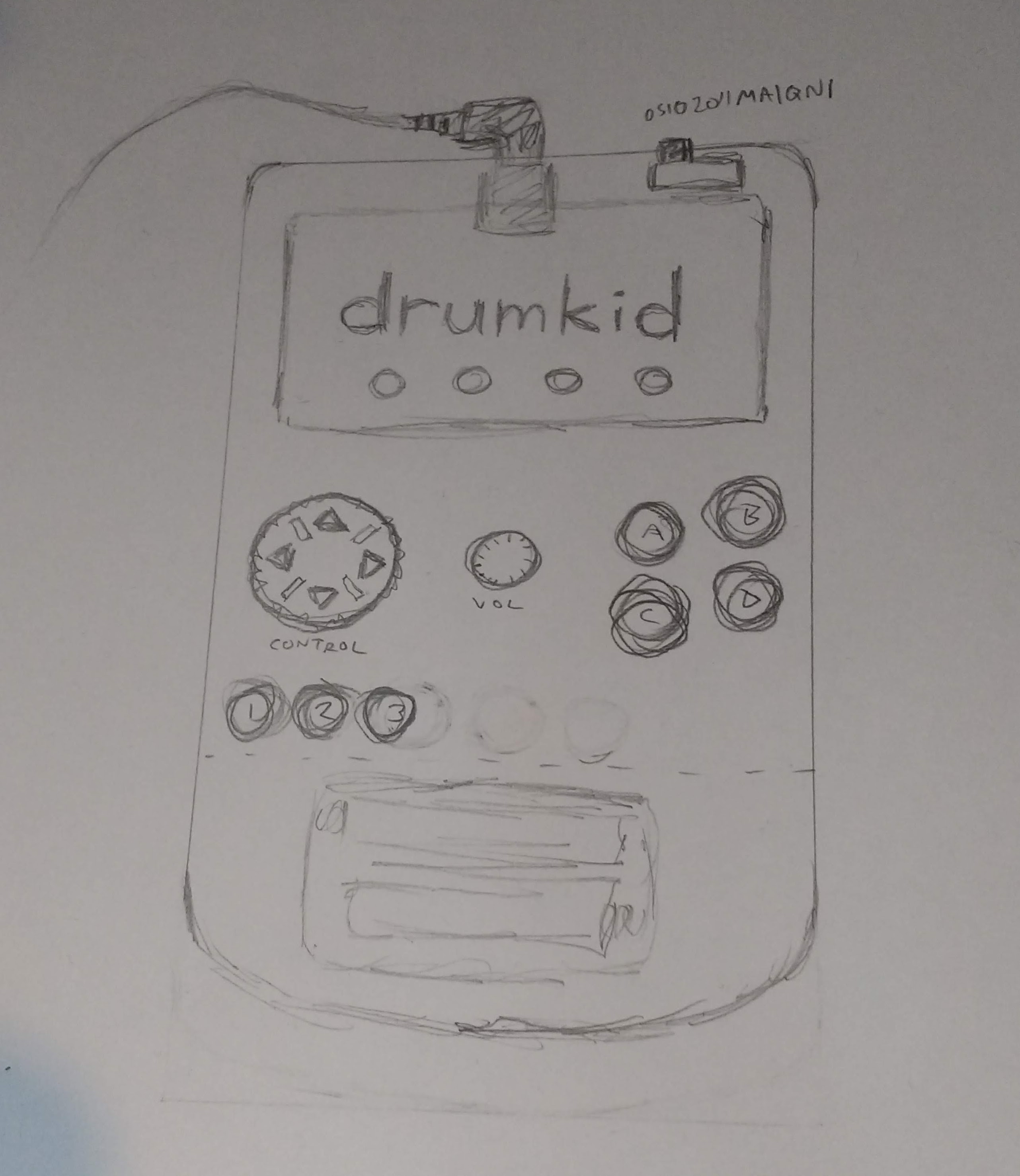
The design would allow me to keep the PCB below 10cm by 10cm, which keeps the cost down, with space to spare for a battery compartment at the bottom.
I'm pretty new to KiCad. I've only designed one previous board (a timer with an LED display), but it did end up working, so I was optimistic about being able to design a decent PCB for DrumKid. In case anyone's interested, I learnt KiCad from Shawn Hymel's excellent YouTube series:
While creating the schematic in KiCad, I realised that I was only using 9 of the Teensy's 20 pins, and in a fit of immaturity decided to add five LEDs to the PWM pins. My reasoning was a) they might be useful for visual feedback, b) LEDs look cool, and c) if I decide not to use them, I can just not solder them and I don't even have to revise the PCB - win-win!
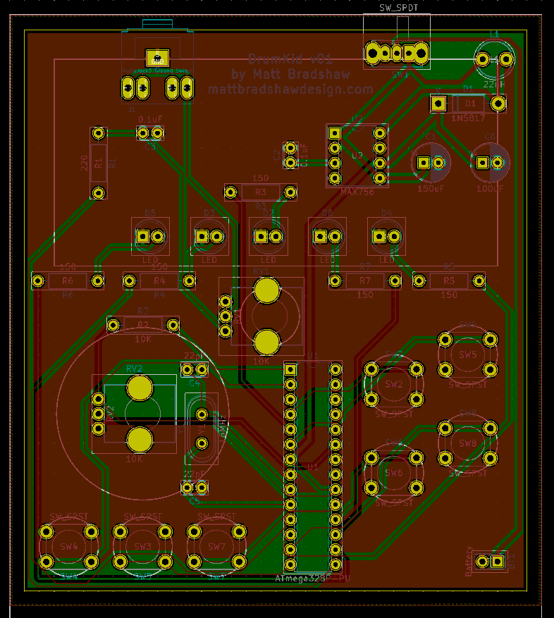
Anyway, I made the schematic, laid out the board, generated Gerber files and sent the design to JLCPCB. I'm off on holiday for a week, but hopefully the boards will arrive not long after I'm back, at which point I can solder everything in place and see if it works.
Discussions
Become a Hackaday.io Member
Create an account to leave a comment. Already have an account? Log In.