 Marcin Saj
Project can be found on crowdfunding campaign: https://igg.me/at/nixieshield
Parameters & Components
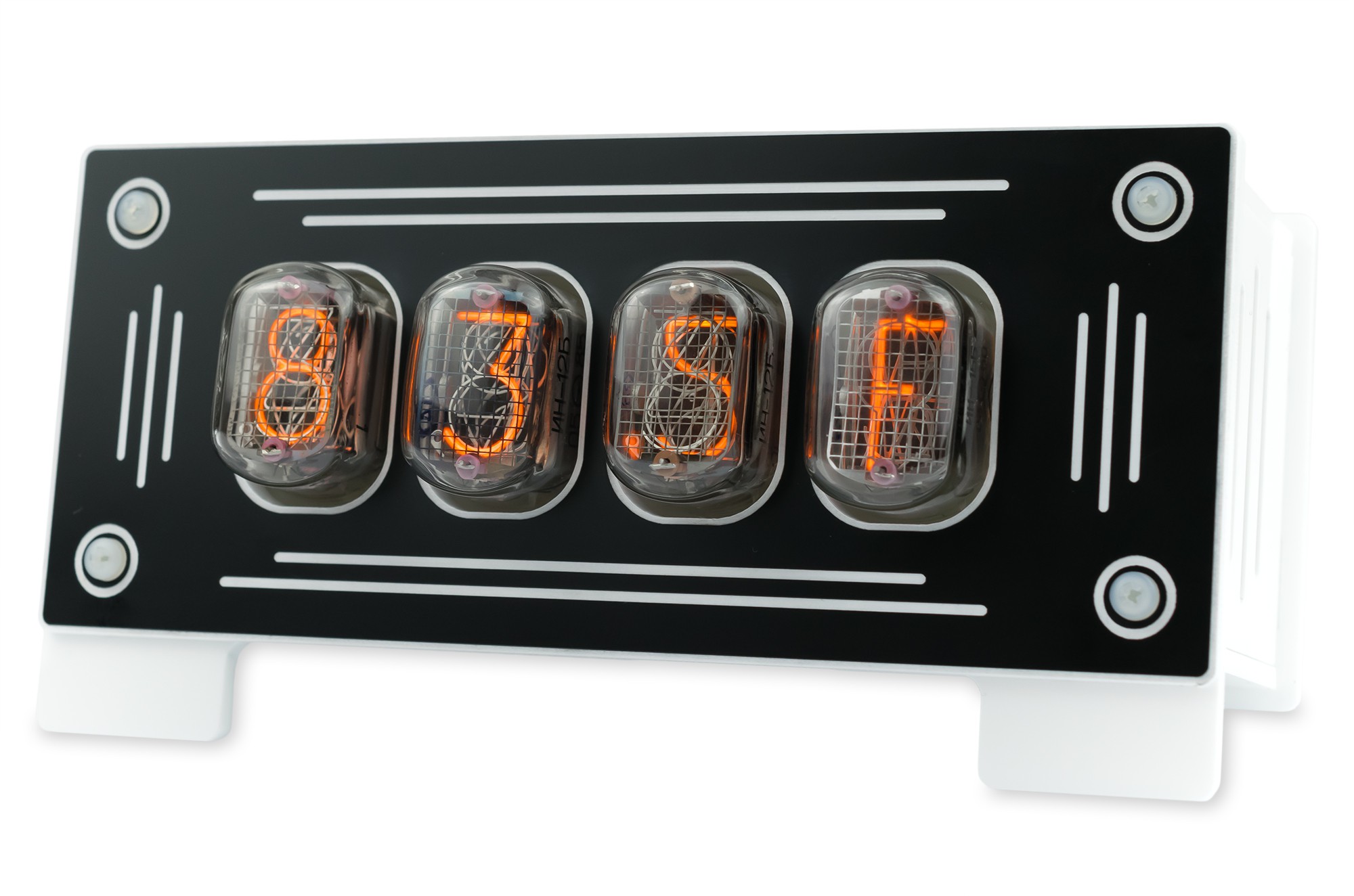
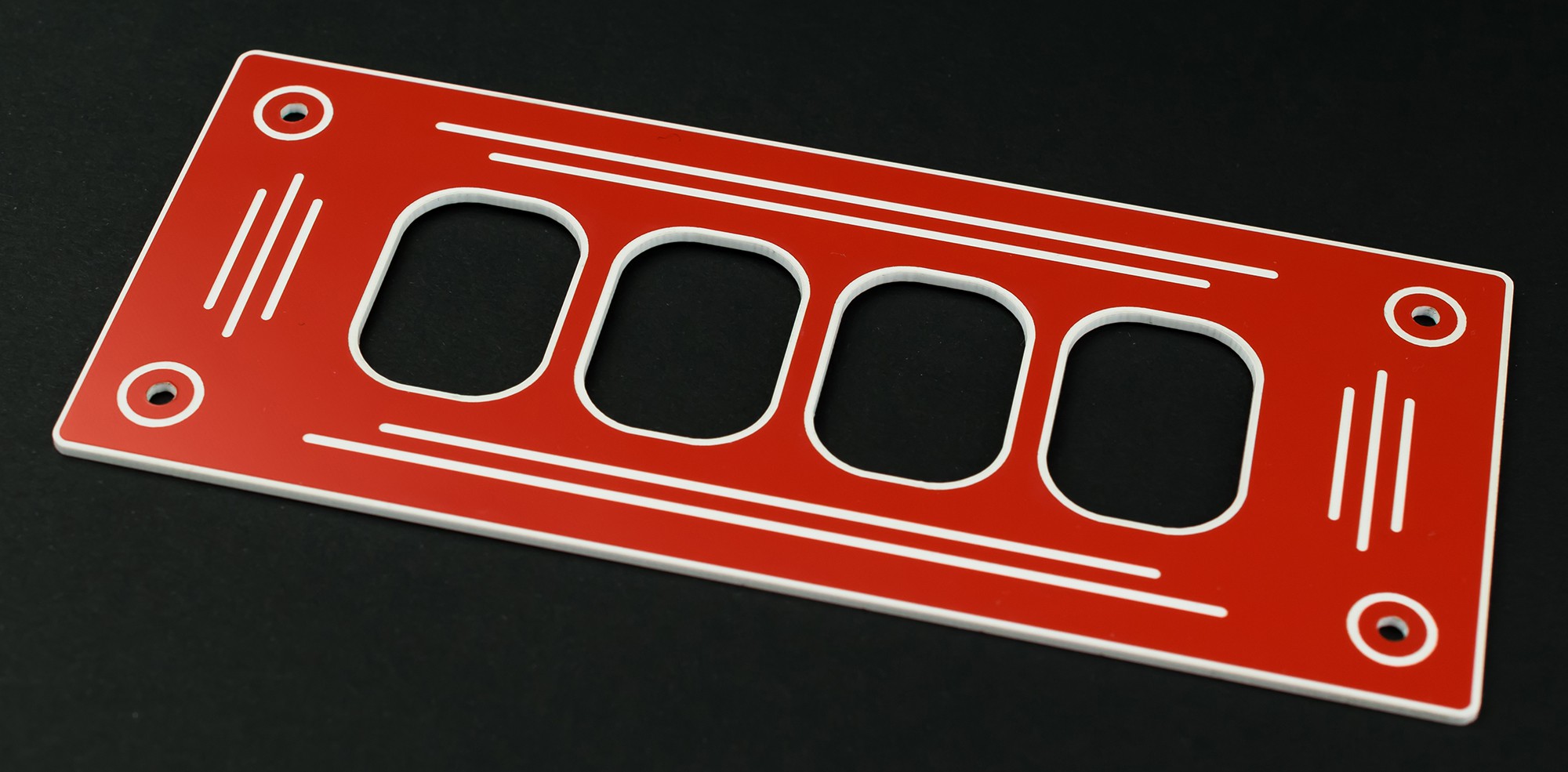
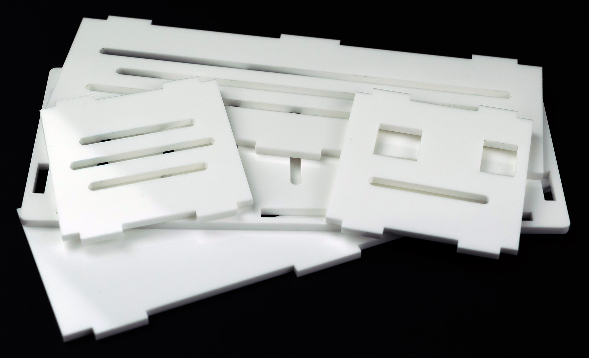
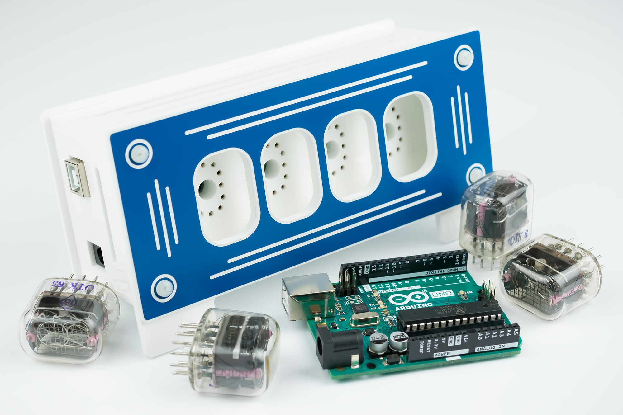
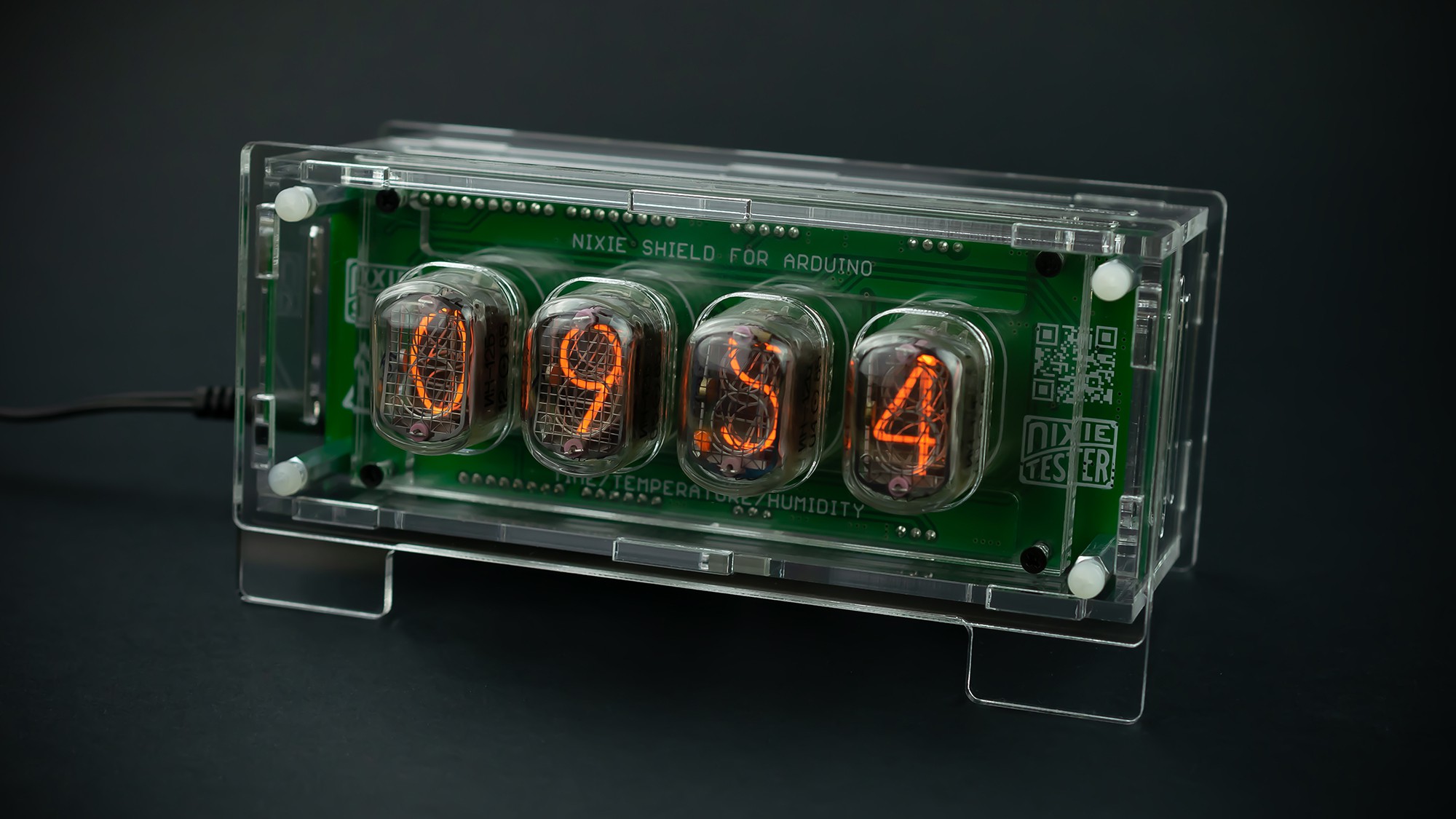
- Perfect quality housing (color: black, red, blue), laser-cut and engraved
- Housing dimensions: 60 x 80 x 158 mm (~2.4" x 3.1" x 6.2")
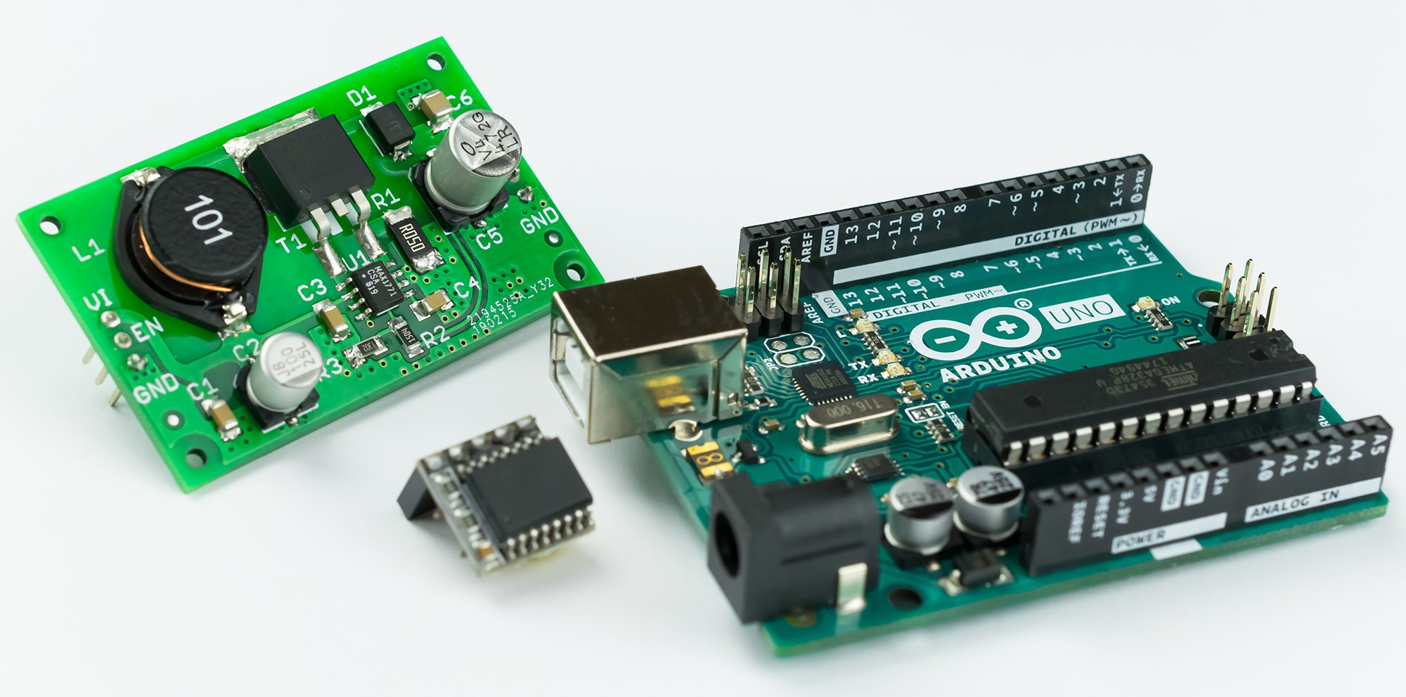
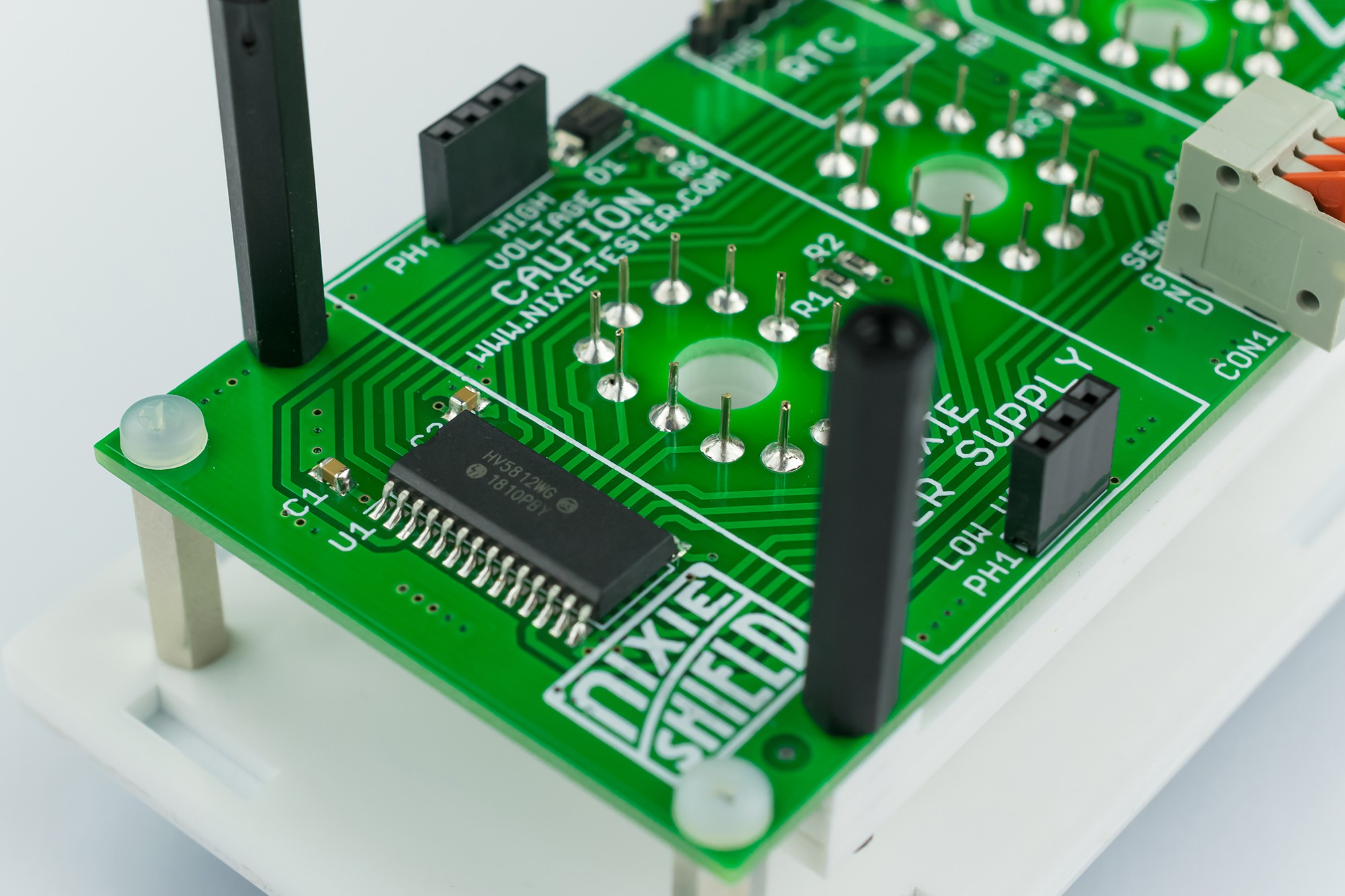
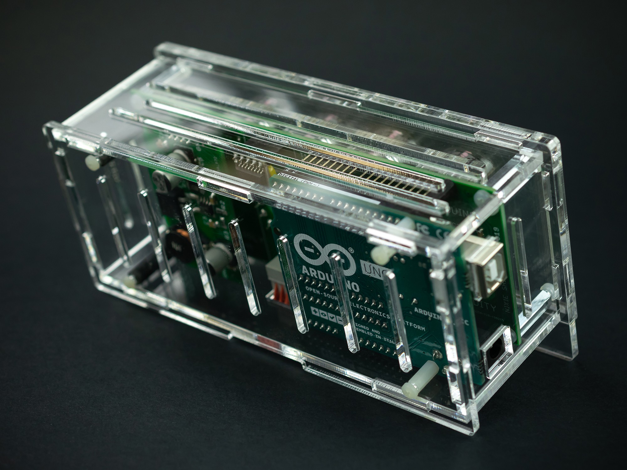
- High quality connectors & pin headers (only these components require soldering)
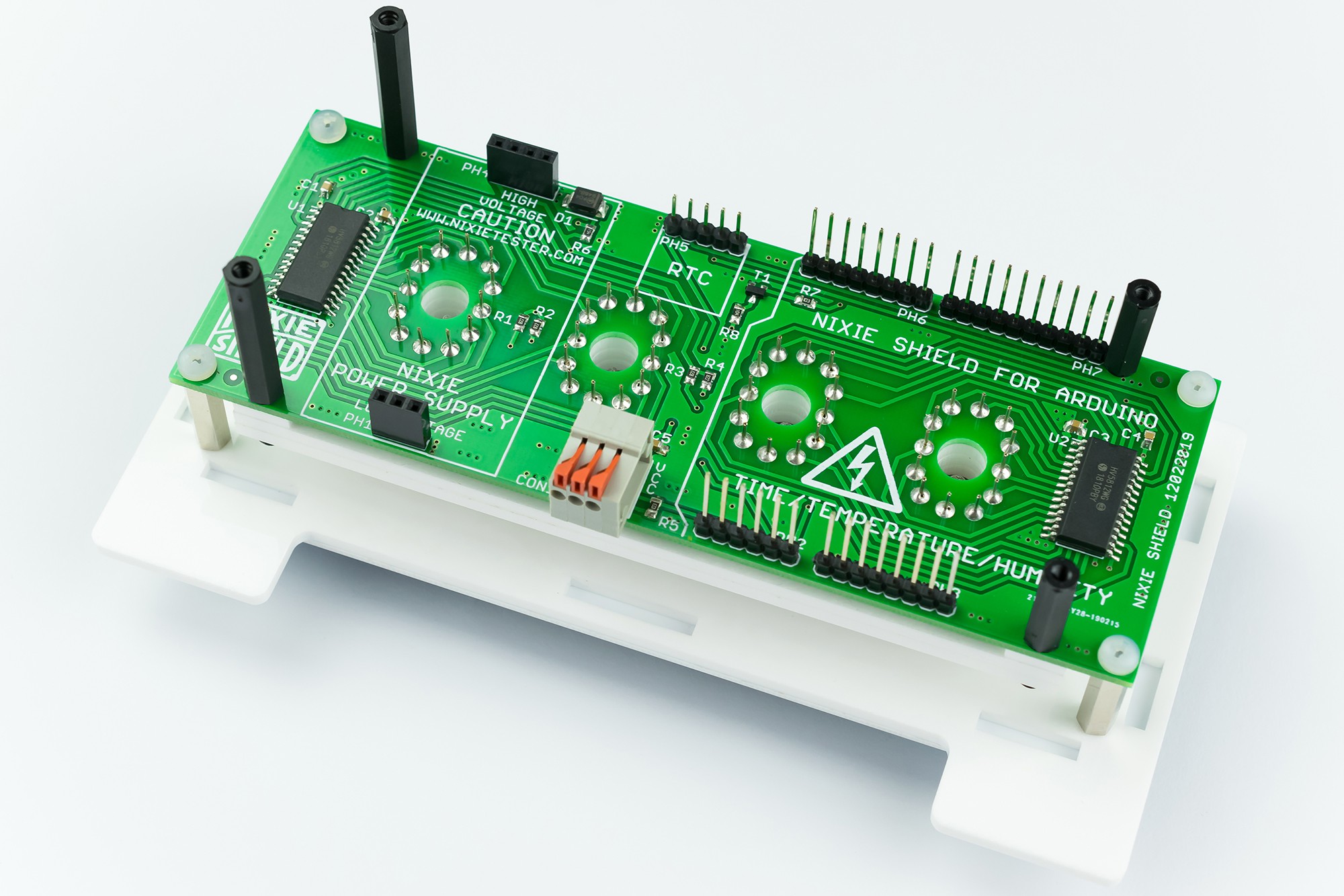
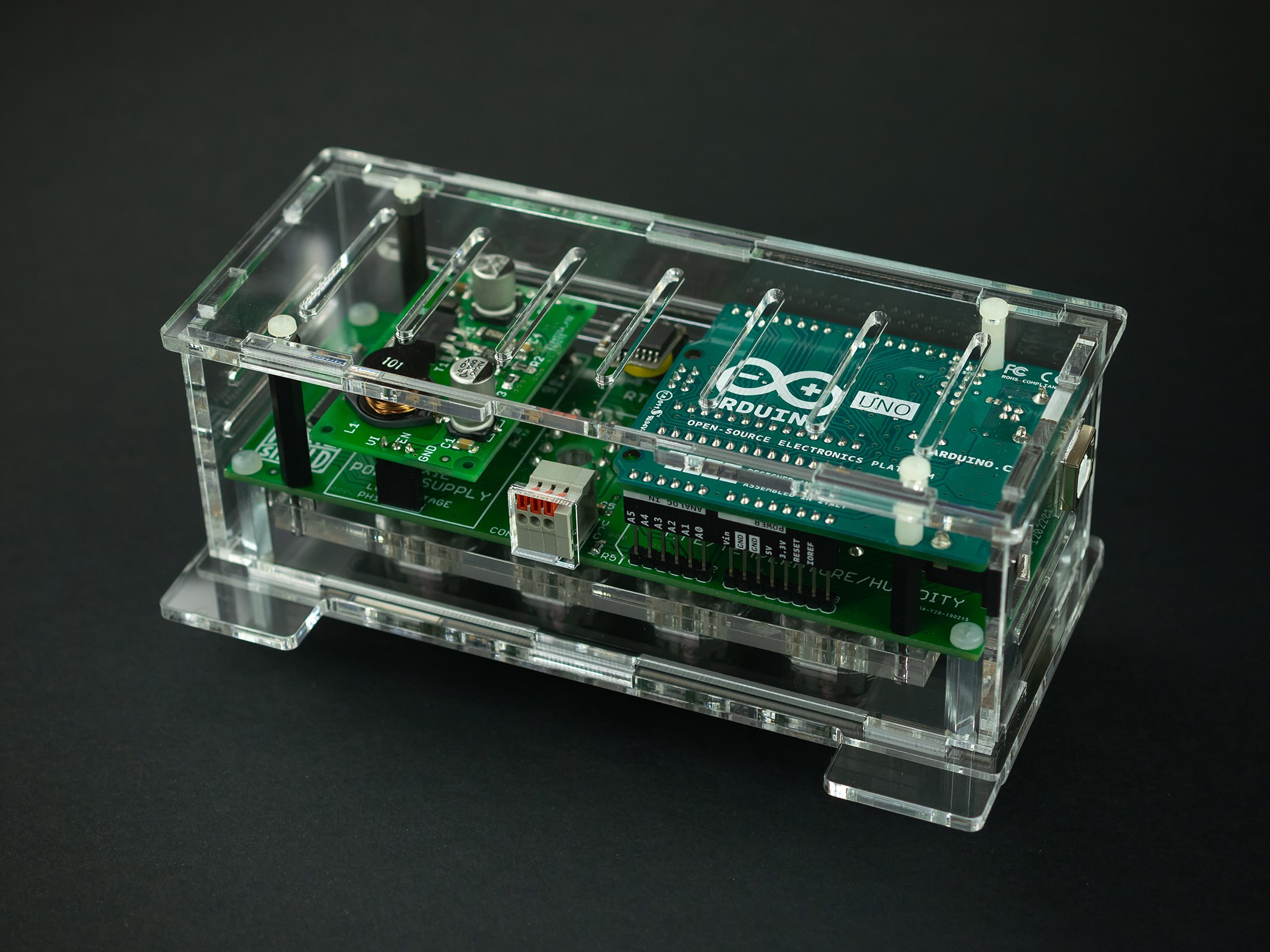
- Nixie power supply module 170V
- Extremely accurate RTC module - DS3231
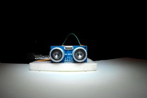
- Precise and accurate temperature & humidity sensor DHT22
- Shield requires +12V power supply (Arduino Vin power supply connector)
- Compatible with Arduino UNO
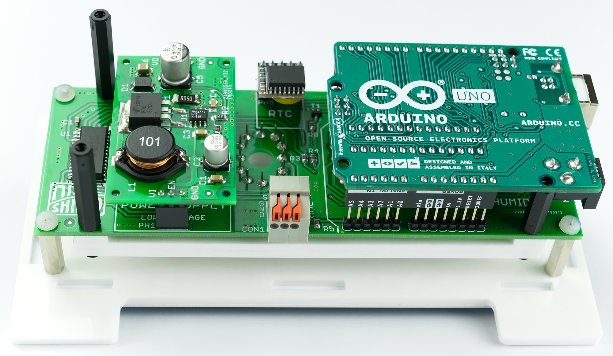
How does this work?
What's Inside
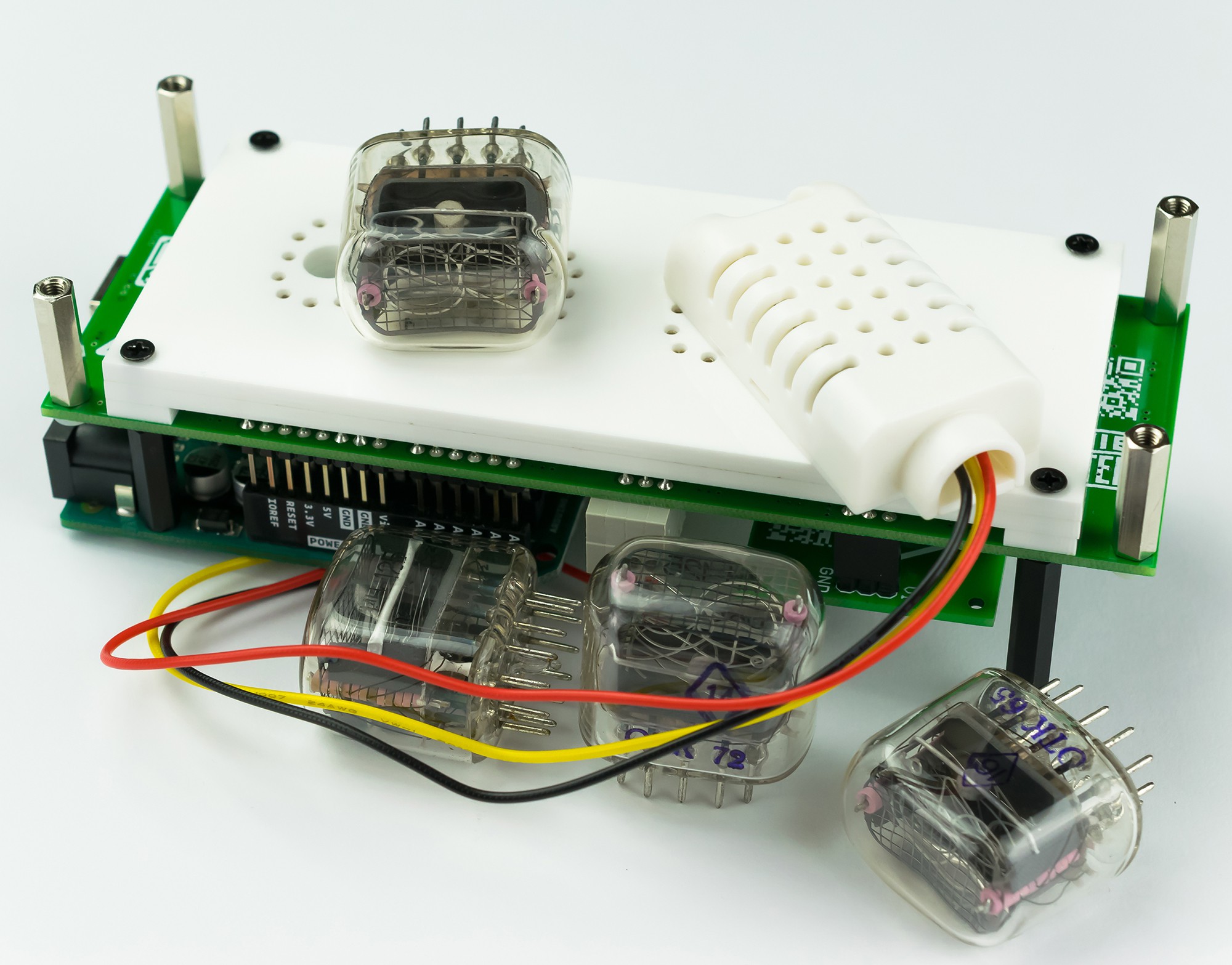


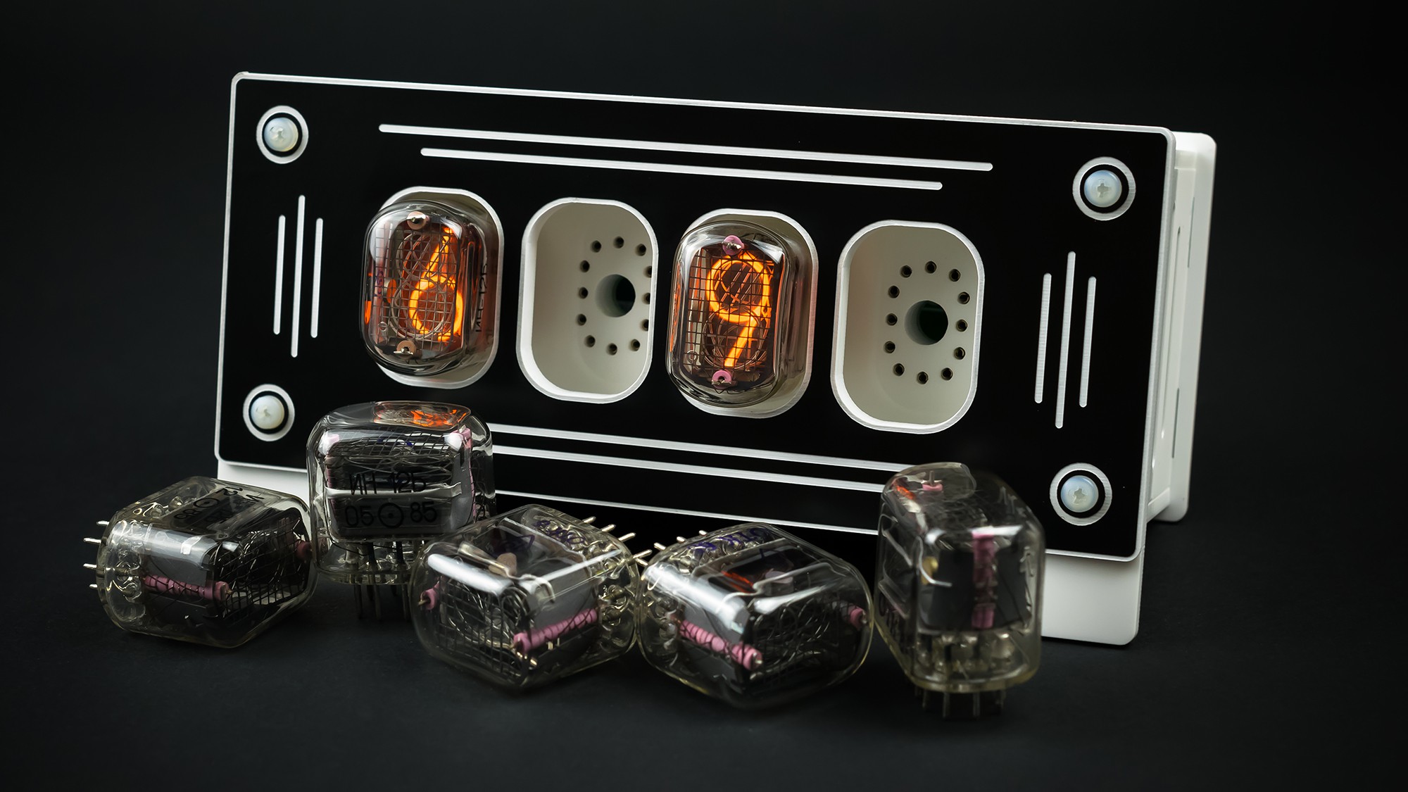
Replaceable Nixie Tubes
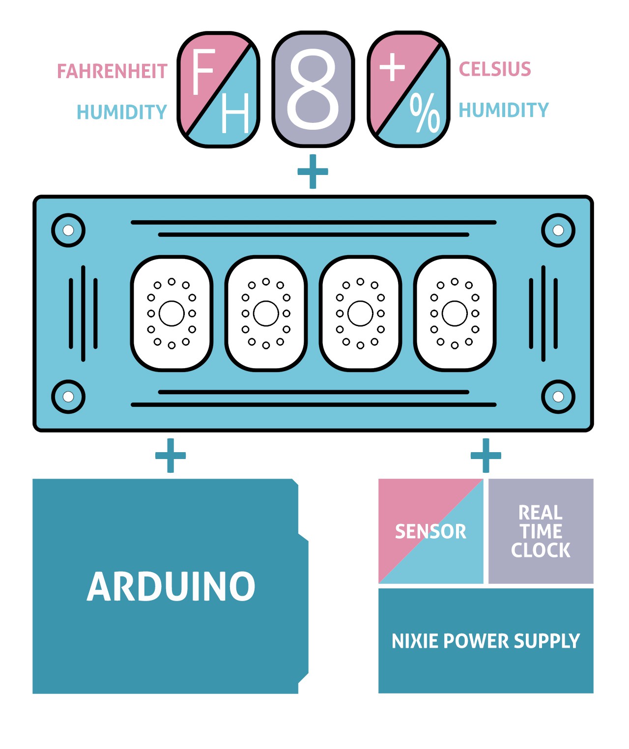
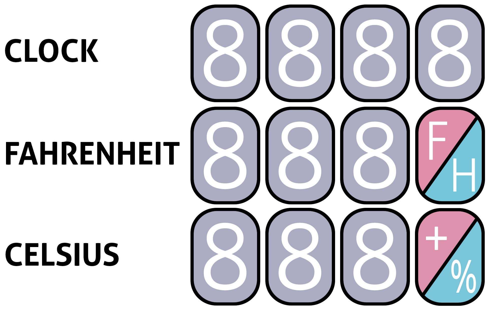
Three device options are possible:
- Nixie Clock - 4 x IN-12B Nixie Tubes
- Fahrenheit - Nixie Thermometer/Hygrometer - 3 x IN-12B + IN-15B Nixie Tubes
- Cesius - Nixie Thermometer/Hygrometer - 3 x IN-12B + IN-15A Nixie Tubes
Easy Arduino Coding
Datasheet and examples codes can be found in the project repository.
Code is very simple and uses only two Arduino libraries: for real time clock DS3231 and second for temperature and humidity sensor DHT22. Nixie tubes are controlled by HV5812 high voltage drivers by using only 3 arduino pins. You can modify the code according to your own ideas.

// Nixie Clock Thermometer Hygrometer Arduino Shield by Marcin Saj https://nixietester.com
// https://github.com/marcinsaj/Nixie-Clock-Thermometer-Hygrometer-Arduino-Shield
//
// Driving Nixie Tubes Example
//
// This example demonstrates how to display digits on nixie tubes. Settings are sent via a serial monitor.
// The control is carried out using two HV5812 drivers: http://ww1.microchip.com/downloads/en/DeviceDoc/20005629A.pdf
// The HV5812 is a 20-channel serial-input display driver. It combines a 20-bit CMOS shift register,
// data latches and control circuitry with high-voltage MOSFET outputs.
//
// Hardware:
// Arduino Uno & Nixie Clock Thermometer Hygrometer Arduino Shield
// Schematic: http://bit.ly/Nixie-Clock-Thermometer-Hygrometer-Arduino-Shield-Schematic
// EN        connected to Arduino pin A2
// DIN       connected to Arduino pin 12
// CLK       connected to Arduino pin A1
// STR       connected to Arduino pin A0
// DATA      connected to Arduino pin A3
// DOT       connected to Arduino pin 4
// RTC SDA   connected to Arduino pin SDA
// RTC SCL   connected to Arduino pin SCL

#define EN    A2     // Nixie Power Supply Module: "0" - ON, "1" - OFF
#define DIN   12     // HV5812 serial data input
#define CLK   A1     // HV5812 data shift register clock input
#define STR   A0     // HV5812 output enable input
#define DOT   4      // Nixie tube dot symbol


// Bit array for 4 nixie tubes, 10 bits for each tube
boolean nixieDisplayArray[40];

// Assignment of the connected cathodes to the position in the 40 bit array
// Each cathode of nixie tubes is connected to the corresponding output of the HV5812 driver
int nixie1[]={26, 27, 28, 29, 20, 21, 22, 23, 24, 25};
           //  0,  1,  2,  3,  4,  5,  6,  7,  8,  9

int nixie2[]={33, 32, 31, 30, 39, 38, 37, 36, 35, 34};
           //  0,  1,  2,  3,  4,  5,  6,  7,  8,  9

int nixie3[]={ 8,  7,  6,  5,  4,  3,  2,  1,  0,  9};
           //  0,  1,  2,  3,  4,  5,  6,  7,  8,  9

int nixie4[]={11, 12, 13, 14, 15, 16, 17, 18, 19, 10};
           //  0,  1,  2,  3,  4,  5,  6,  7,  8,  9

int digit1, digit2, digit3, digit4;


void setup()
{
    Serial.begin(9600);

    // Initialize connected pins as an output
    pinMode(EN, OUTPUT);
    digitalWrite(EN, HIGH);     // Turn off NPS - Nixie Power Supply Module

    pinMode(CLK, OUTPUT);       // Nixie driver data shift register clock input
    digitalWrite(CLK, LOW);

    pinMode(DIN, OUTPUT);       // Nixie driver serial data input
    digitalWrite(DIN, LOW);

    pinMode(STR, OUTPUT);       // Nixie driver output enable input
    digitalWrite(STR, LOW);

    pinMode(DOT, OUTPUT);       // Nixie tube dot
    digitalWrite(DOT, HIGH);    // Turn on nixie dot

    delay(3000);

    digitalWrite(EN, LOW);      // Turn on NPS - Nixie Power Supply Module
}

void loop()
{
    Serial.print("Enter a number from range 0-9999: ");

    // Wait...
Read more »

 ken.do
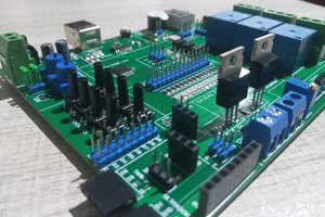
 ElectronicABC
 Rob Englebright