My board design had a LOT of problems.
Let's take inventory of my mistakes, so you can hold them against me:
- The address connections A16 and A17 from the VRAM to the uPD7220 were not set up completely right, causing a strange monitor flicker in mixed mode, and lack of memory access if the software didn't have a special setup
- VRAM control lines were not generated correctly
- The VRAM was not fast enough to do what I had in mind. I thought I checked this and I knew the timing was close, so I must have done my math wrong.
- Probably something else I forgot
I thought there might be a minor issue or two with the design, as the design of the VRAM access is very ambitious - accessing two words per cycle using careful timing, then switching what device controls the memory every other cycle. Yes, a lot can go wrong. But what I didn't expect, is that so much would go wrong. I practically have to re-design more than half the board. Well, that is more or less what I've been working on.
Here's a video showing what the debugging was like; hopefully the video isn't too chaotic:
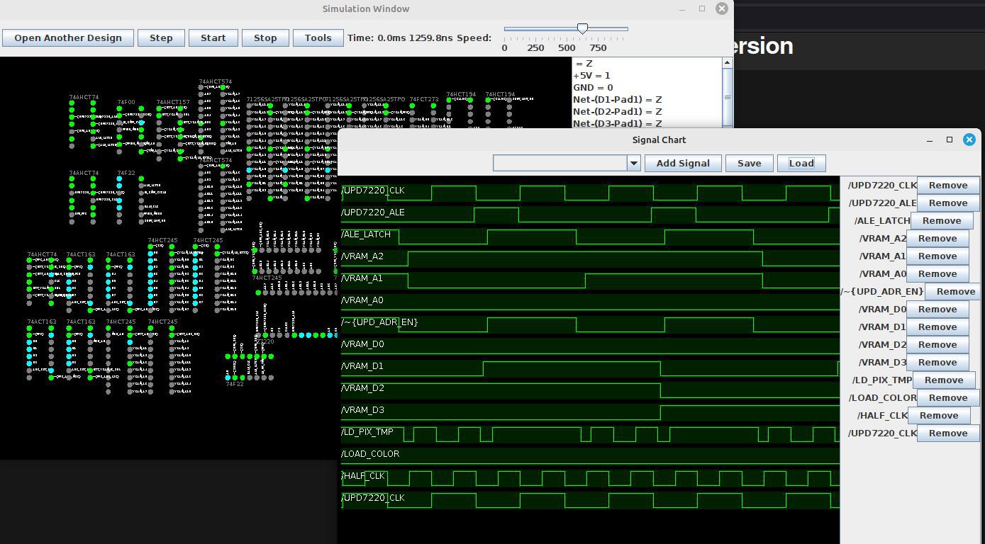
At some point I realized that I couldn't figure this all out by messing with the hardware directly - there were just too many things wrong with the board. The breadboard was losing me both signal integrity and voltage - the board ran at less than 4.3v. I needed a simulator. Well, I wrote one. It works decently well, loads my schematics straight from KiCad, can show me the VGA video output, and has a few other random features. Here's the source on my personal gitlab server, and here is a picture of it:
 It is VERY alpha, and the library of components is incredibly limited. It has bugs and the UI can crash sometimes. That being said, the simulation itself does not seem to have any problems. It does just one thing extremely well: it simulates the card I'm working on. With some relatively small upgrades it could probably be used to simulate a wide variety of digital circuits.
In any case, I've been using this simulator to work on a fixed design. This is still in progress; I'll post one more log when I order the boards, then I can try again when I receive the improved boards. I'll go over my changes to the board in depth on the next log, but basically I've switched the SRAM ICs to 25ns chips so I can get the timing I want, and I've removed most of the logic gates and replaced them with MUXs to make something akin to LUTs - kinda like an FPGA with TTL, except the LUTs are hardwired. Much easier and more reconfigurable than trying to use gates - and in some cases it's actually faster too. Well, until next time. Wish me luck on a fixed design!
 Dylan Brophy
Discussions
Become a Hackaday.io Member
Create an account to leave a comment. Already have an account? Log In.