Update – 20190826
You always seem to find errors when it's too late for changes :)
- used interrupt pin in the "wrong way":
- switching it to +Vbat (via 50k, so the high voltage doesn't kill the pin)
- forgot pull-down resistor
The right way would've been: using the internal pull-up and switching to GND...
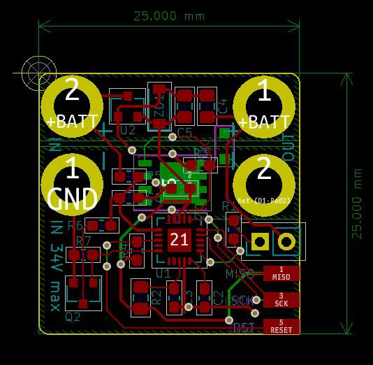
C4 should've been directly tied to the regulators input. It is connected correctly to +VBAT and GND, but not as close as possible to the regulator. As the whole board is only 25x25mm it shouldn't be a problem though...
Update – 20190816
Today I finished my square inch design and ordered it at Aisler:
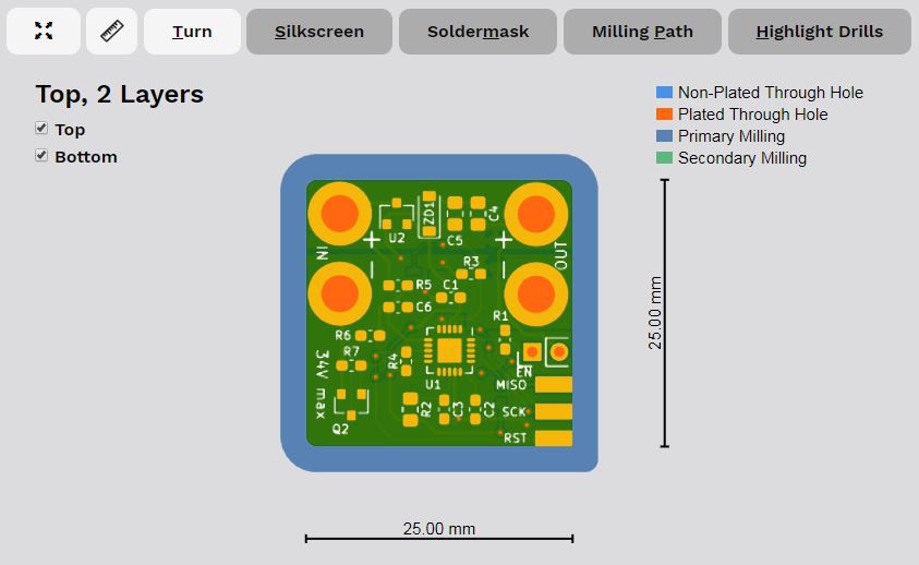
This time I added a stainless stencil for top and bottom because I hate adding solder paste with a toothpick or syringe :)
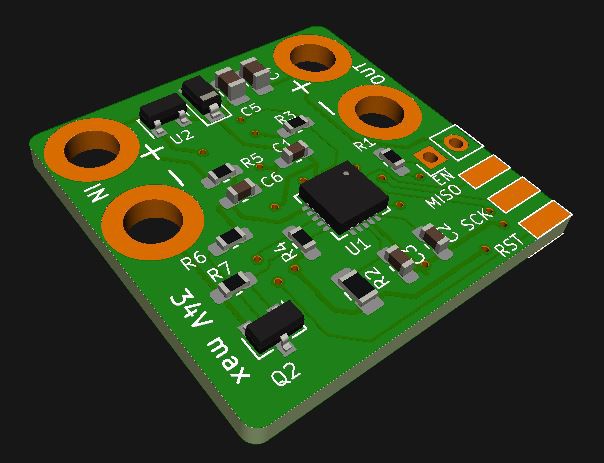
Intro
For a few of my planned projects I need the board to be quite small. So I made a very basic version. It misses all the nice "usability" features, the bigger board has.
Facts
The cut-off parameters are set once while programming (and can of course be re-programmed) and there are not LEDs to show the state of the board.
Off-current should be well below 10µA, working-current will be around 1mA when measuring, which is around 10% of the time (while not measuring the Attiny shuts down), so let's assume the working current is around 15% of 1mA, so 0.15mA averaged over time...
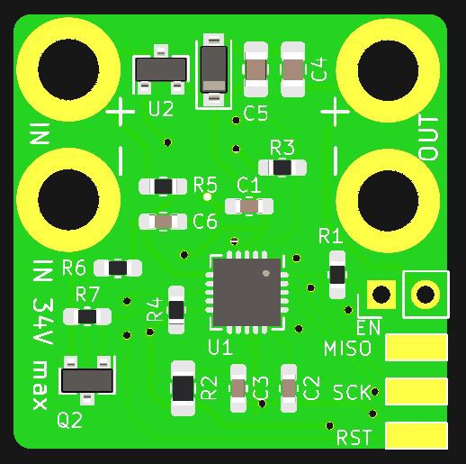
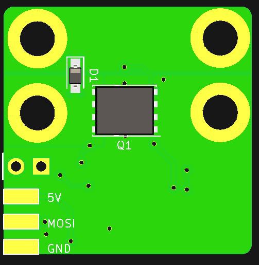
The board is 25x25mm in size, it will fit into many many tight spots!
 Jan
Jan
Discussions
Become a Hackaday.io Member
Create an account to leave a comment. Already have an account? Log In.