 Dan Maloney
Turns out that soldering 20 resistors between two big plates of copper is a non-trivial task. Who'da thunk?
The design goals of Big Dummy are a little grander. What I wanted was a dummy load with more power handling - 50 watts preferably - and a way to tap off the transmitter's output so I can make some measurements. I also want to make a "Cantenna"-style load - built into a paint bucket and filled with dielectric oil for cooling. I don't know why - it just seems cool. Plus, I want the thing to be usable not just in the HF bands but hopefully also at VHF and maybe even UHF. Lastly, I want it to look good.
After looking at all sorts of designs and searching for cheap and easily available components, I settled on 20 1-k thick-film resistors in parallel. That gives 50 ohms of impedance, and with 2-watt resistors, that should dissipate 40 watts - close enough to 50. My plan was to build it into a small (one quart, or about a liter) paint can. I wanted to suspend the resistors between two copper plates for low parasitic capacitance and good power dissipation, so I ordered up some 24-AWG copper sheet off Amazon. It's about 0.5-mm thick, which doesn't sound like much but. it's more than enough. I had no idea going in how hard this decision was going to make the project.
For the testing connection, I modified a design from K7AGE that's pretty simple. His dummy used eight 100-ohm power resistors in a series-parallel arrangement to get 50 ohms total. That allowed him to tap off the center of two of the series resistances, treating them like a voltage divider. That goes to the test point through a 1N5711 Schottky diode, with a small ceramic decoupling cap across the test points.
I suck at EDA software - so far - so I just did a quick Fritzing schematic:
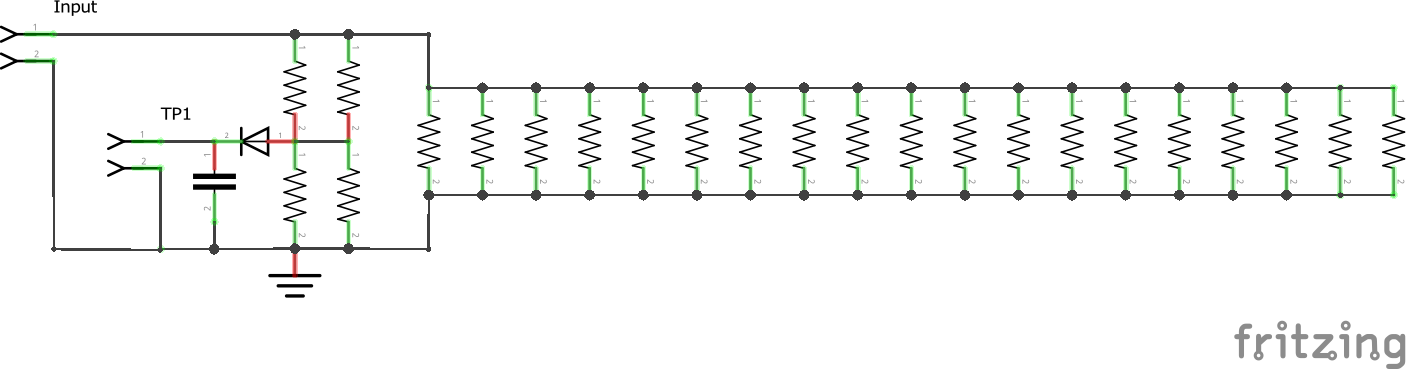
All I had was 1000-ohm resistors, so I had to do a series-parallel network to provide the voltage divider needed for the test point. That was a fun bit of soldering:
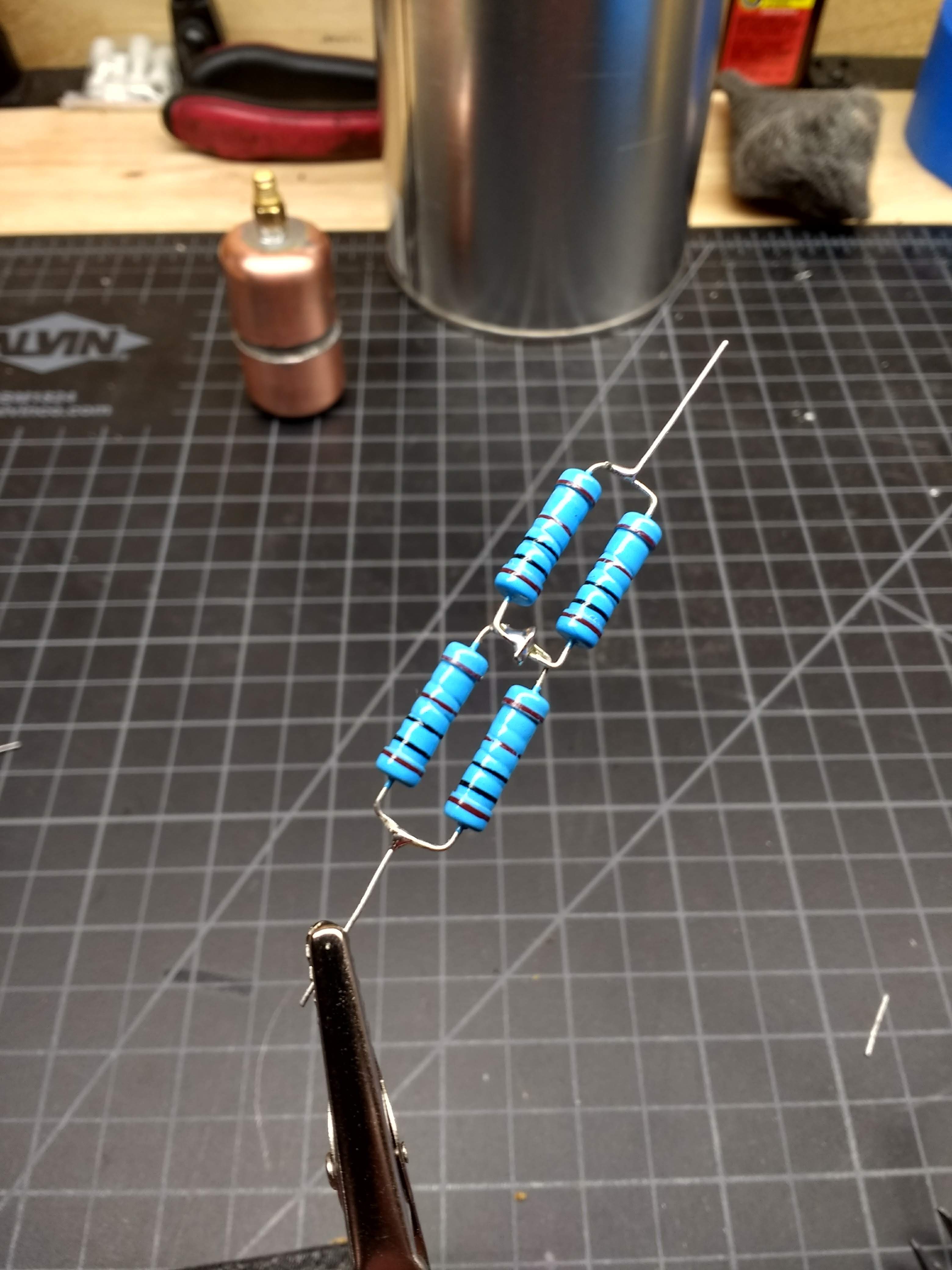
I dig circuit sculptures...
While soldering these, i noticed that the appeared to be wire-wound - see the spiral grooves? I destructively tested one, just to be sure they were actually metal-film:
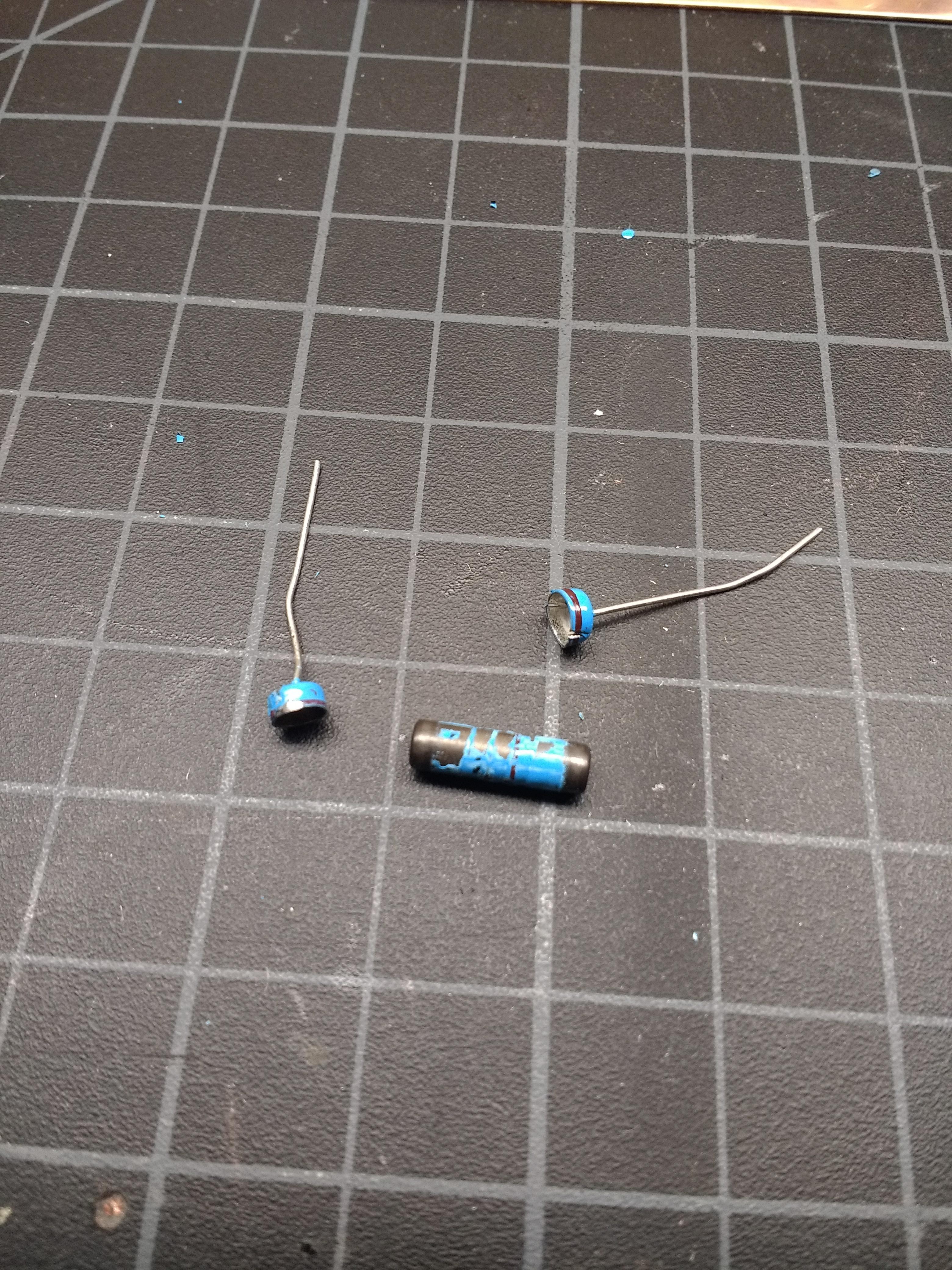
Yup - solid slug of material. The grooves must be how they fine-tune the resistance.
Discussions
Become a Hackaday.io Member
Create an account to leave a comment. Already have an account? Log In.