 Kevin Arne
New Boards
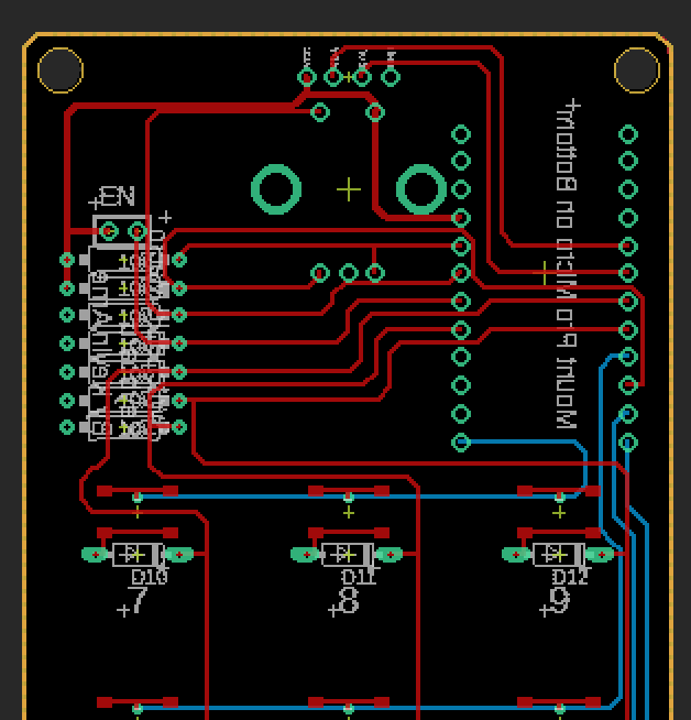
As previously mentioned, I goofed on the LCD panel, so I spun a new board with the I2C lines broken out to headers. That meant moving a lot of pins around both to make the I2C lines open and make the routing easier to do on a single layer. Still didn't quite make it all on a single layer mostly because of the rows and columns of the keypad. I'm an amateur at this, so feedback is welcome.
LCD Panel
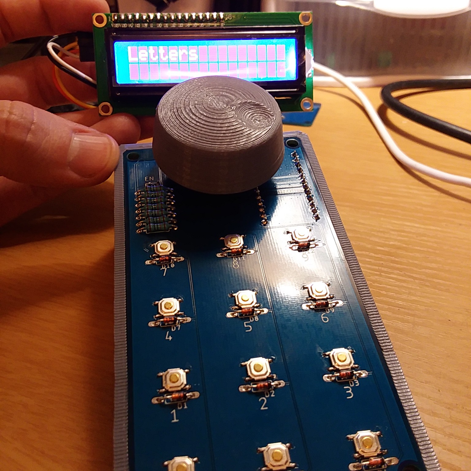
The LCD panel now displays the current keyboard's name. At first I had the code try to update the display as soon as the keyboard changed, totally forgetting that I probably shouldn't/can't do that in an interrupt. I still need to add some checks to make sure folks don't put keyboard names that don't display well (or somehow cause a crash).
Next Steps
I need to redesign the enclosure to include the LCD panel. I also want to be able to send some unusual commands using things like the control key and shift key, so I have to figure out how I'm going to structure the keyboard data to allow for that. Finally, I'd like to clean everything up so I can feel comfortable posting both the PCB layout and code to GitHub so other folks can make use of it.
Discussions
Become a Hackaday.io Member
Create an account to leave a comment. Already have an account? Log In.