I am developing for the Ultratronics v1.0 which is a Arduino Due.
This is done in Visual Studio 2015 and a tool: VisualMicro.
Developing the code is not easy because I have been slamming into a wall for a few days before I started to realize that the compiler may not produce correct code for what I wanted.
It seems that inside classes the C++ does not like "MyClass* myClass=new
MyClass()" on the Arduino Due. Dynamic memory allocation seems not to
function nicely. Something that would have worked correctly on a Windows C++.
It forced me to a redesign. Less dynamic assigned memory and more static compile time determined memory.
But I have results:
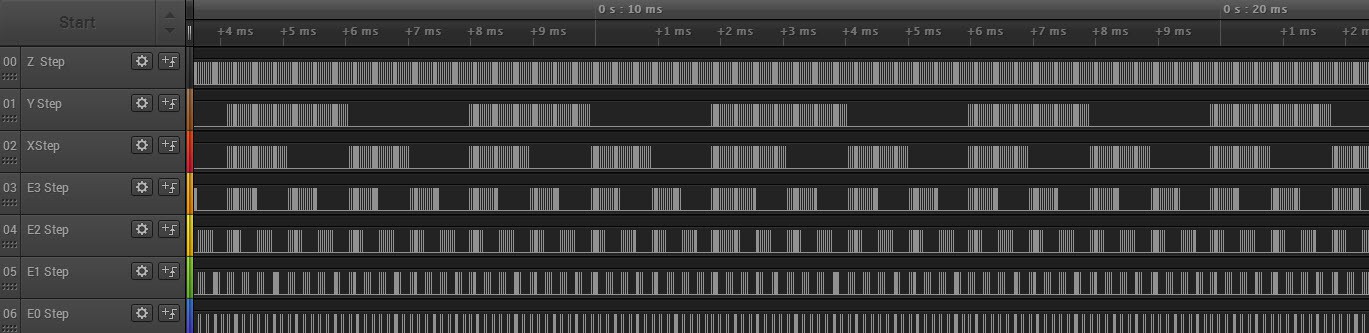
Hooking up the logic analyzer shows the clear test pattern.Each puls is a stepper motor step command.
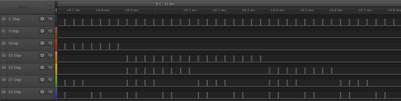
Zoomed in
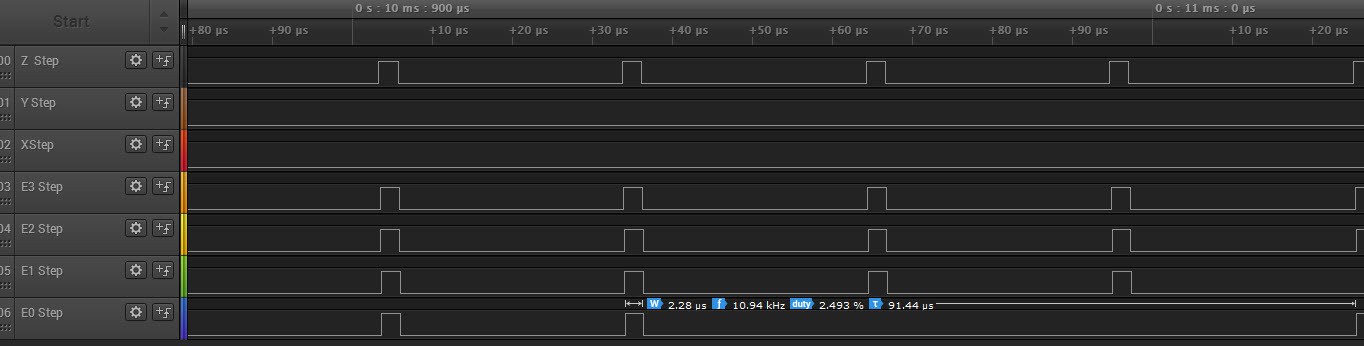
Zooming even more in you clearly short pulses that are a bit higher than 2µS.
The code that generates the puls is below. I use one bit per motor to drive the simultaneously. Then a silly loop with a "nop" in it that generates a pulse with that is a bit higher than the required 2µS
void MotorCommand::StepMotorPulseDelay2Micros() {
    // Code blow should be about 2 µS on a 84 Mhz Arduino Due
    for (auto i = 0; i < 36; ++i) {
        asm("nop \n");
    }
}
void MotorCommand::SendMotorStepCommand(byte step_command) {
	// Make the signal high
	SendMotorStepHighCommand(step_command);
	StepMotorPulseDelay2Micros();

	// Make the signal low
	SendMotorStepLowCommand(step_command);
	StepMotorPulseDelay2Micros();
}

void MotorCommand::SendMotorStepHighCommand(byte step_command) {
    byte level = step_command;

    level = step_command & MOTOR_BIT_Z;
    if (level != 0) REG_PIOD_SODR = PIO_PD0;        // Z_AXIS_STEP set to high, bit 7

    level = step_command & MOTOR_BIT_Y;
    if (level != 0) REG_PIOB_SODR = PIO_PB26;        // Y_AXIS_STEP set to high, bit 6

    level = step_command & MOTOR_BIT_X;
    if (level != 0) REG_PIOC_SODR = PIO_PC3;        // X_AXIS_STEP set to high, bit 5

    level = step_command & MOTOR_BIT_E3;
    if (level != 0) REG_PIOC_SODR = PIO_PC7;        // E3_AXIS_STEP set to high; bit 4

    level = step_command & MOTOR_BIT_E2;
    if (level != 0) REG_PIOA_SODR = PIO_PA19;        // E2_AXIS_STEP set to high, bit 3

    level = step_command & MOTOR_BIT_E1;
    if (level != 0) REG_PIOC_SODR = PIO_PC19;        // E1_AXIS_STEP set to high, bit 2

    level = step_command & MOTOR_BIT_E0;
    if (level != 0) REG_PIOC_SODR = PIO_PC16;        // E0_AXIS_STEP set to high, bit 1
}

void MotorCommand::SendMotorStepLowCommand(byte step_command) {
    REG_PIOD_CODR = PIO_PD0;                        // Z_AXIS_STEP set to low
    REG_PIOB_CODR = PIO_PB26;                       // Y_AXIS_STEP set to Low
    REG_PIOC_CODR = PIO_PC3;                        // X_AXIS_STEP set to Low
    REG_PIOC_CODR = PIO_PC7;                        // E3_AXIS_STEP set to low
    REG_PIOA_CODR = PIO_PA19;                       // E2_AXIS_STEP set to low
    REG_PIOC_CODR = PIO_PC16;                       // E0_AXIS_STEP set to low
    REG_PIOC_CODR = PIO_PC19;                       // E1_AXIS_STEP set to low
    return;
}
The idea is to have pre-calculated motor bits ready in memory that can, be read at a fast rate and executed by a timer. The time above is at 32Khz, which means that a 200 Steps motor, at 32 microso-steps has about 5 revolutions per second.
This may seem fast but the Thor robot has geared steps with a 5:1 ration and then we have another gear X:1 slowing it even more. I image think about having to have only 16 or maybe even 1 micro step per motor.
Next step direction and enable control.
Discussions
Become a Hackaday.io Member
Create an account to leave a comment. Already have an account? Log In.