-
Thor Base is ready to go
01/06/2017 at 21:06 • 2 commentsSince I received ball bearing 16014 this week, I could finally assemble the base so we can test the full base mechanism driven by a stepper motor.
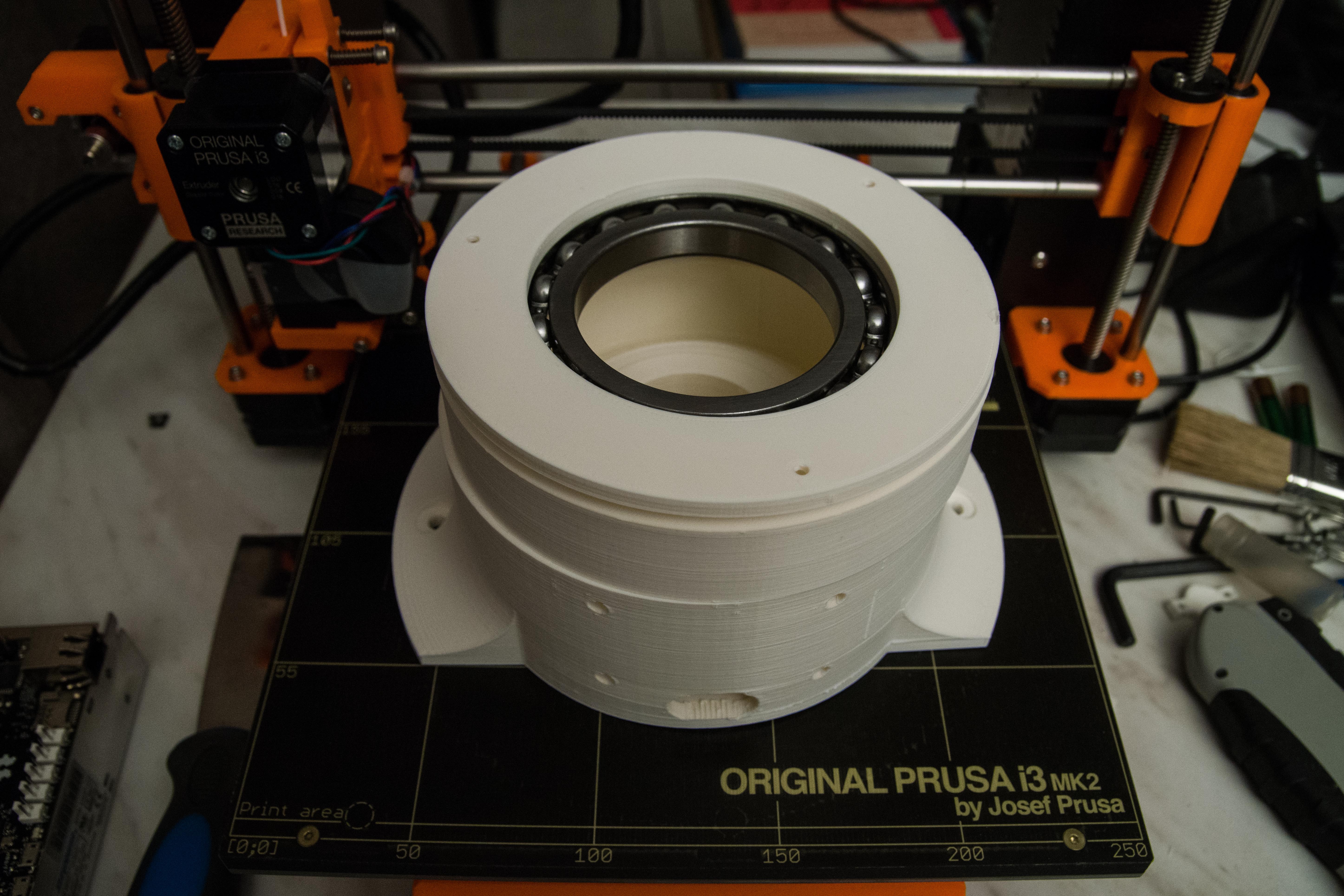
![]()
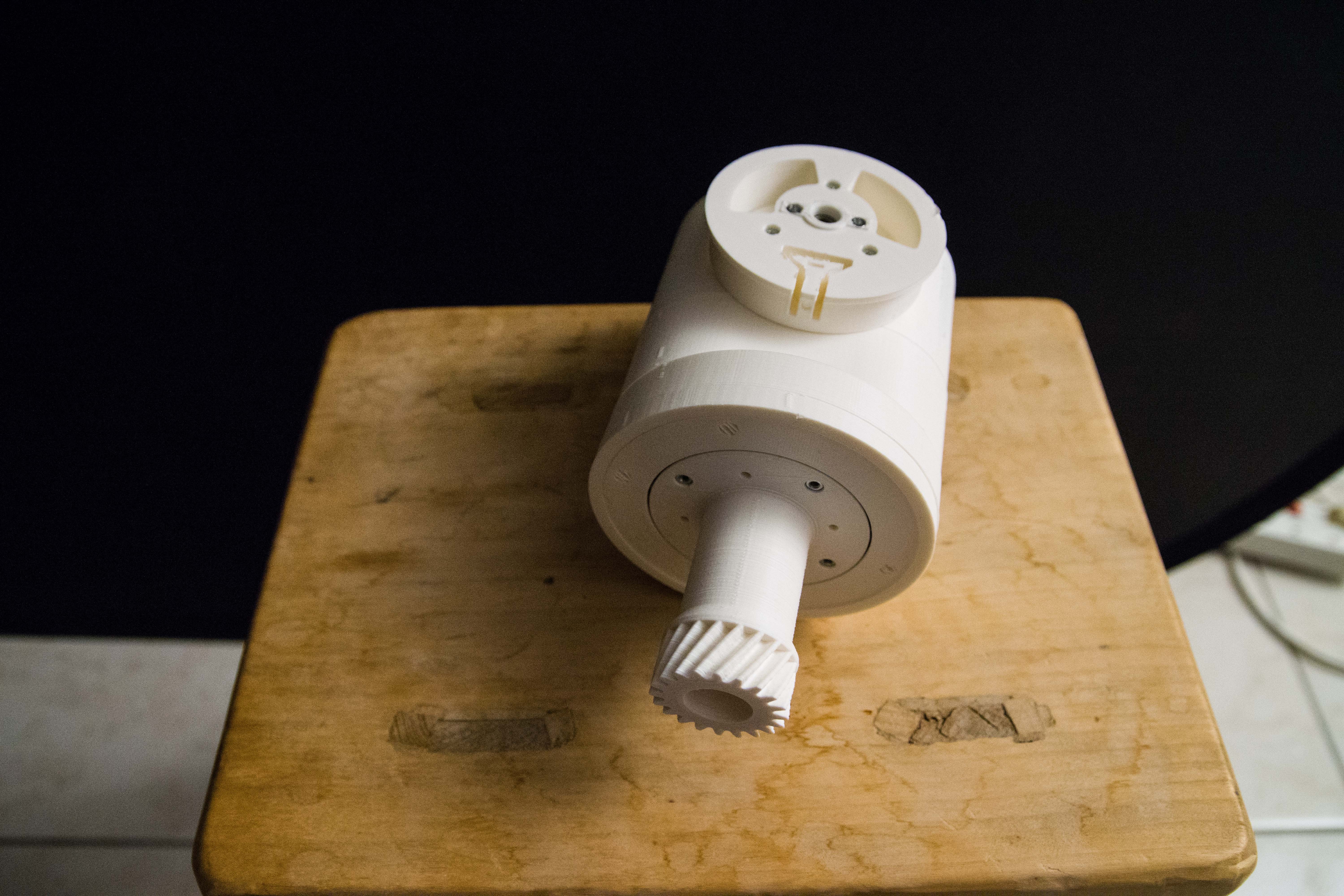
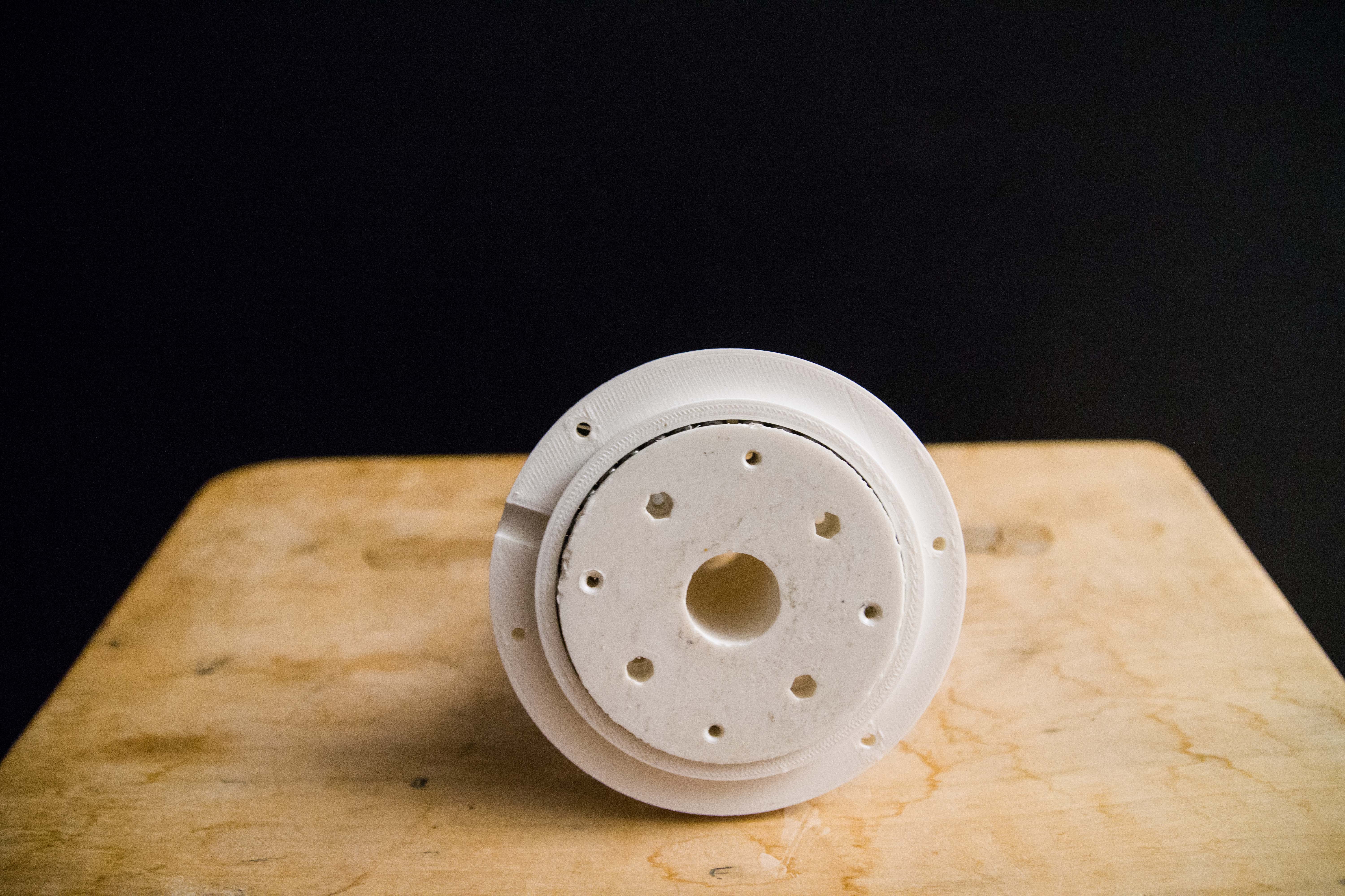
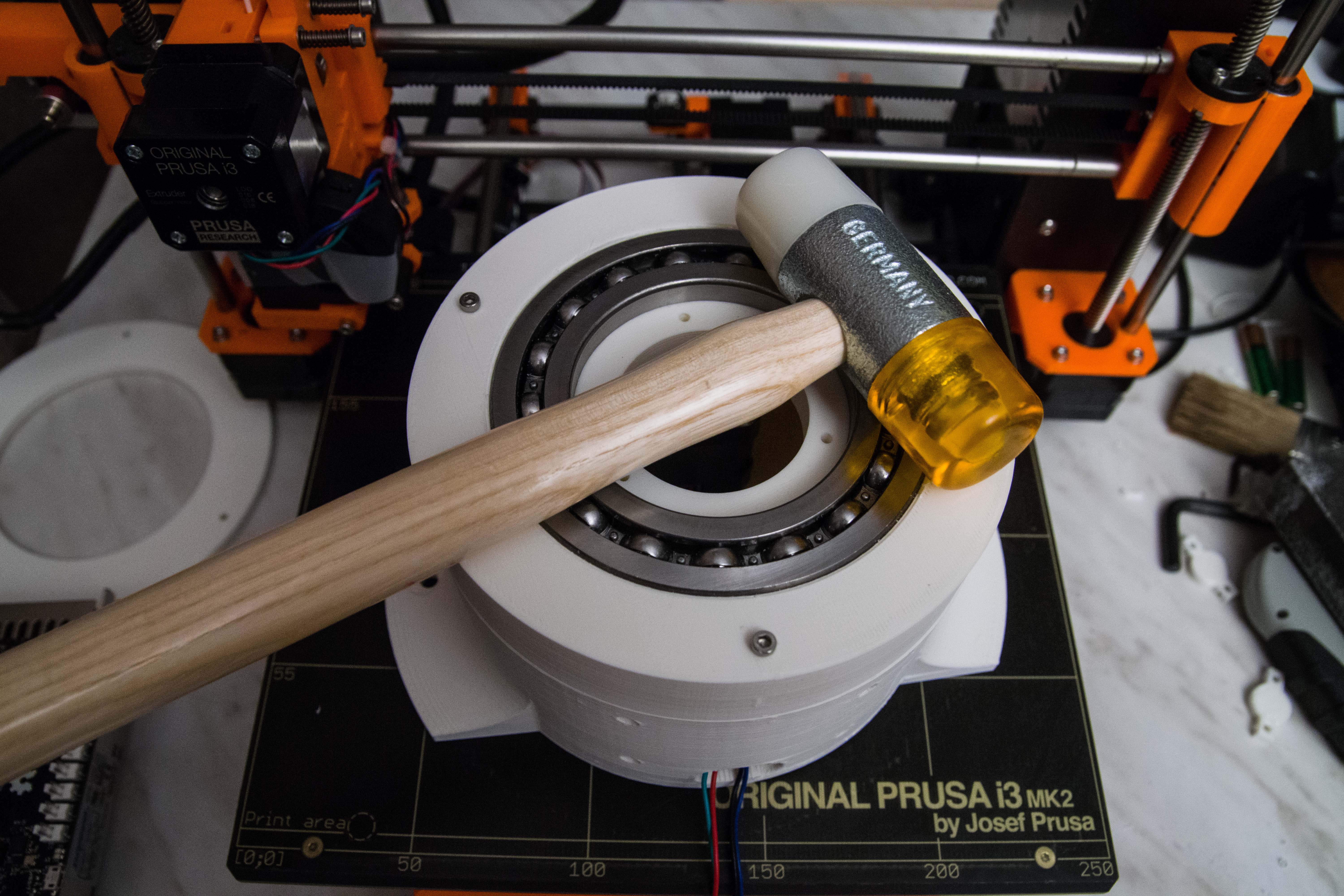
Top view of the base, put on my 3D printer to give a sense of dimensions.
You can clearly see the stepper motor that will drive the inner cog that is hooked to the base top (not shown in this image)
To mount the electric motor you have to remove the screws from the bottom of the stepper motor. Then insert screws that are longer.
There is still a ring (seen at the left side of the photo) that should go onto top if this, so the screws are sunk into the plastic.
Danny And AngelLM and Danny warned me to paint the inner cog black because the translucence of the plastic could give the photo detector a wrong signal the home position.
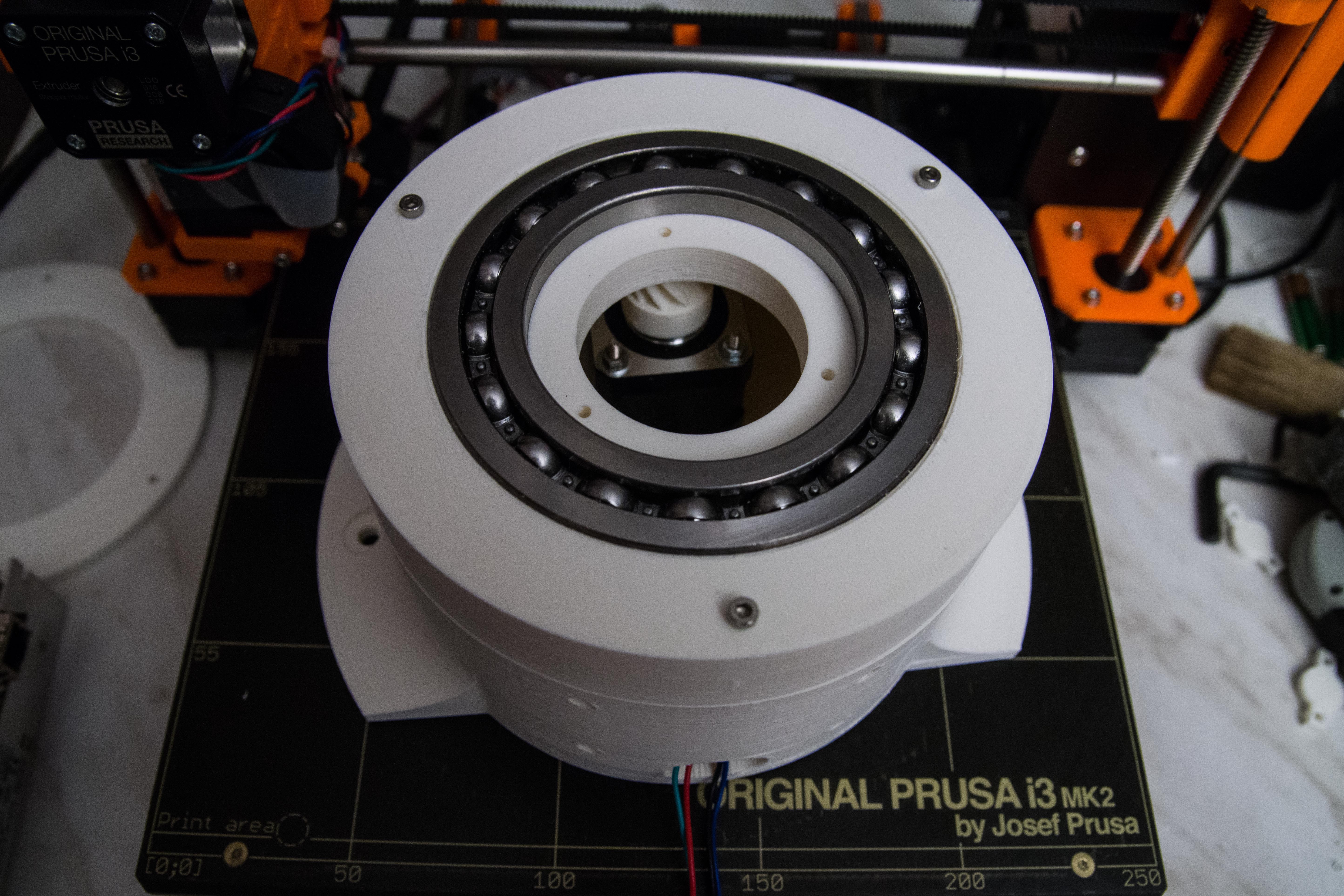
![]()
The ball bearing did not fit the 3D plastic. I think the inner wall was about 2 mm too thick.
I had to scrape the inner wall to make it fit the ball bearing and then slightly hammer it with a soft hammer in place.
-
Move it like a ballet dancer
01/05/2017 at 20:12 • 2 commentsI have been decades in software development and I have always learned that software has a primary function that you must develop towards to. All the rest is secondary.
So what is the main purpose of a robot?
What gives the robot purpose in life?Only one answer: Moving like a ballet dancer!
The reason why I started with the Thor project is because it has 6 freedoms of movement (7 stepper motors). And getting all these motors work elegantly is very challenging. And you can't cheat with badly developed software.
The focus this weekend will be on the very core functionality is moving elegantly.
Thor has 7 stepper motors, the used Ultrasonics v1.0 board will have 7 independent Pololu DVR8825 drivers.
![]() The only way where you get a robot moving like a ballet dancer is when you control those those stepper motor as one entity. They must act like one entity in perfect synchronicity.
The only way where you get a robot moving like a ballet dancer is when you control those those stepper motor as one entity. They must act like one entity in perfect synchronicity.7 motors can be encoded in 7 bits. So using one byte as one step to move them all simultaneously would be nice.
The elegant design of this all is that a mere loop like this would move them at the fastest rate and perfect predictable.
while(true) {
    OUT[0b0111 1111]
    Sleep(10)
    OUT[0b0000 0000]
    Sleep(10)
}
This one loop has a very cool feature in that we can actually slow it down as we like even to a one step by step by pressing a button. As in this code next example
while(true) {
    OUT[0b0111 1111]
    Sleep(10)
    OUT[0b0000 0000]
    Sleep(Delay)
}
In order to know what the steps should be, should come form a FIFO buffer that gets filled by some other source. It is not the job of this loop to waste time on calculating the next step. Its only purpose is to take the next step and execute it.
while(true) {
    byte NextByte=GetNextByte()
    OUT[NextByte]
    Sleep(10)
    OUT[0b0000 0000]
    Sleep(Delay)
}
Since we deal with real physical situations, and robot can be dangerous we need a way to emergency stop or even decelerate.
while(IsSafeToRun) {
    byte NextByte=GetNextByte()
    OUT[NextByte]
    Sleep(10)
    OUT[0b0000 0000]
    var nextDelay=GenNextDelay(IsSafeToRun)
    if (nextDelay<=0) break;
    Sleep(nextDelay)
}
We did not take into account the direction the motors have to move, but between fixed 2 positions the motors don't change direction only the steps to move to the next step is important.
If you wonder how we control the speed of each motor independently the trick is in the FIFO queue that defines the steps for every bit: 0001 11100 0011 11001 1001 10010 1010 1111 111 110 101 01110 0011 1000 11000.... per motor not the change of delay.
How we build this FIFO queue and how to define the correct stepper motor bits that is a whole different topic.
The usage of this FIFO actually has a cool side effect, we have a perfect record how the motors moved and record and replay it.
To speed up calculations we even could use already per-calculated fragment that gets repeated.
In order to have agility response of the robot we could create a mechanism where the FIFO buffers can be cleared and filled with new bit series. Maybe even use a double FIFO that can be swapped to keep the data to the motors constant.
To be continued....
-
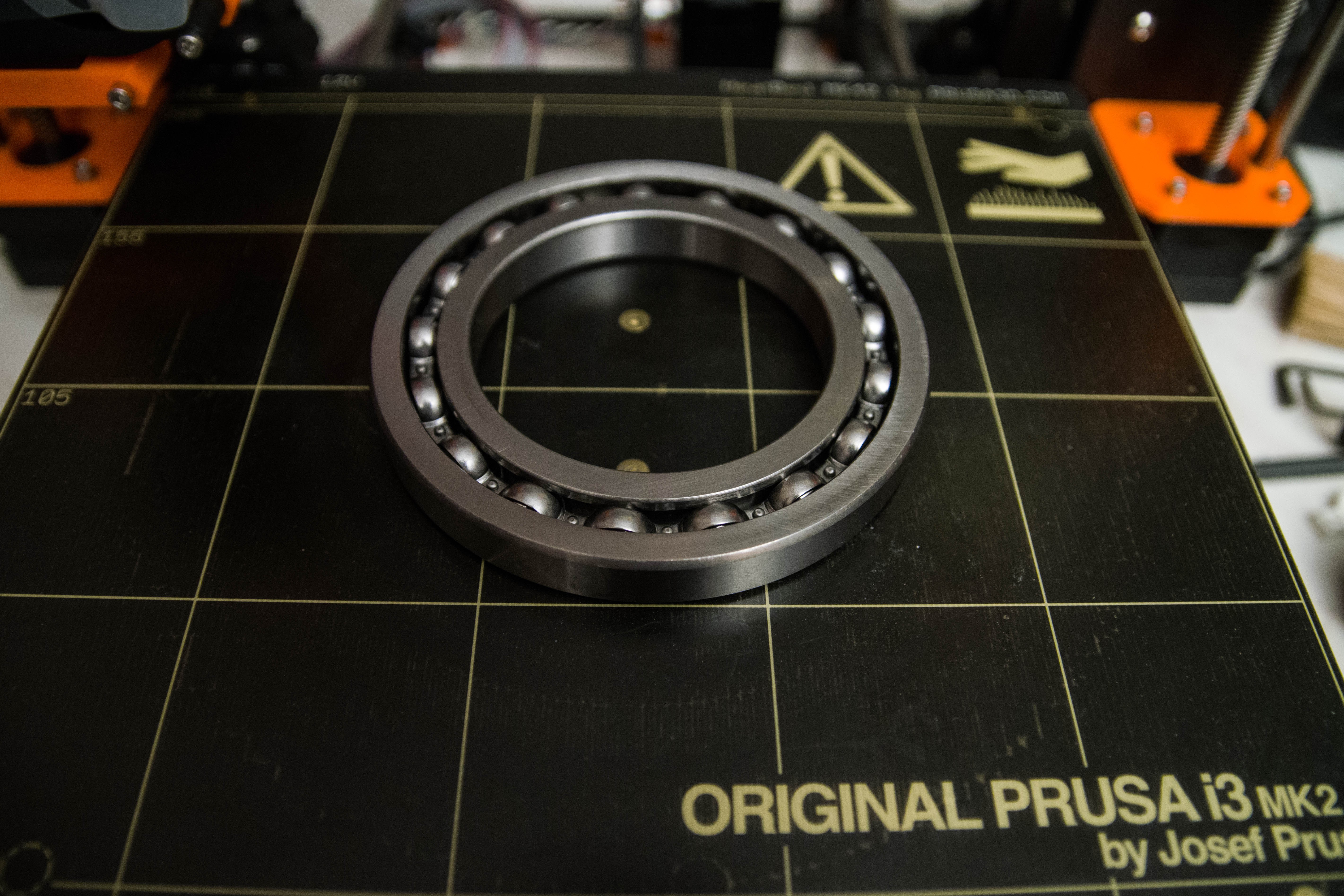
Ball bearing 16014 arrived
01/04/2017 at 21:33 • 5 commentsThe Thor robot has a ball bearing in its base called: 16014. That is one giant ball bearing but it must carry 6 stepper-motors the weight of the arm and payload.
This ball bearing was ordered on Amazon but later cancelled as undeliverable. So I had to find a different shop that sells these ball-bearings that had it in stock and was good in price.
![]()
Put on my 3D printer so you can get a feeling of how big that thing is. The cost was €37 total including shipping and VAT.
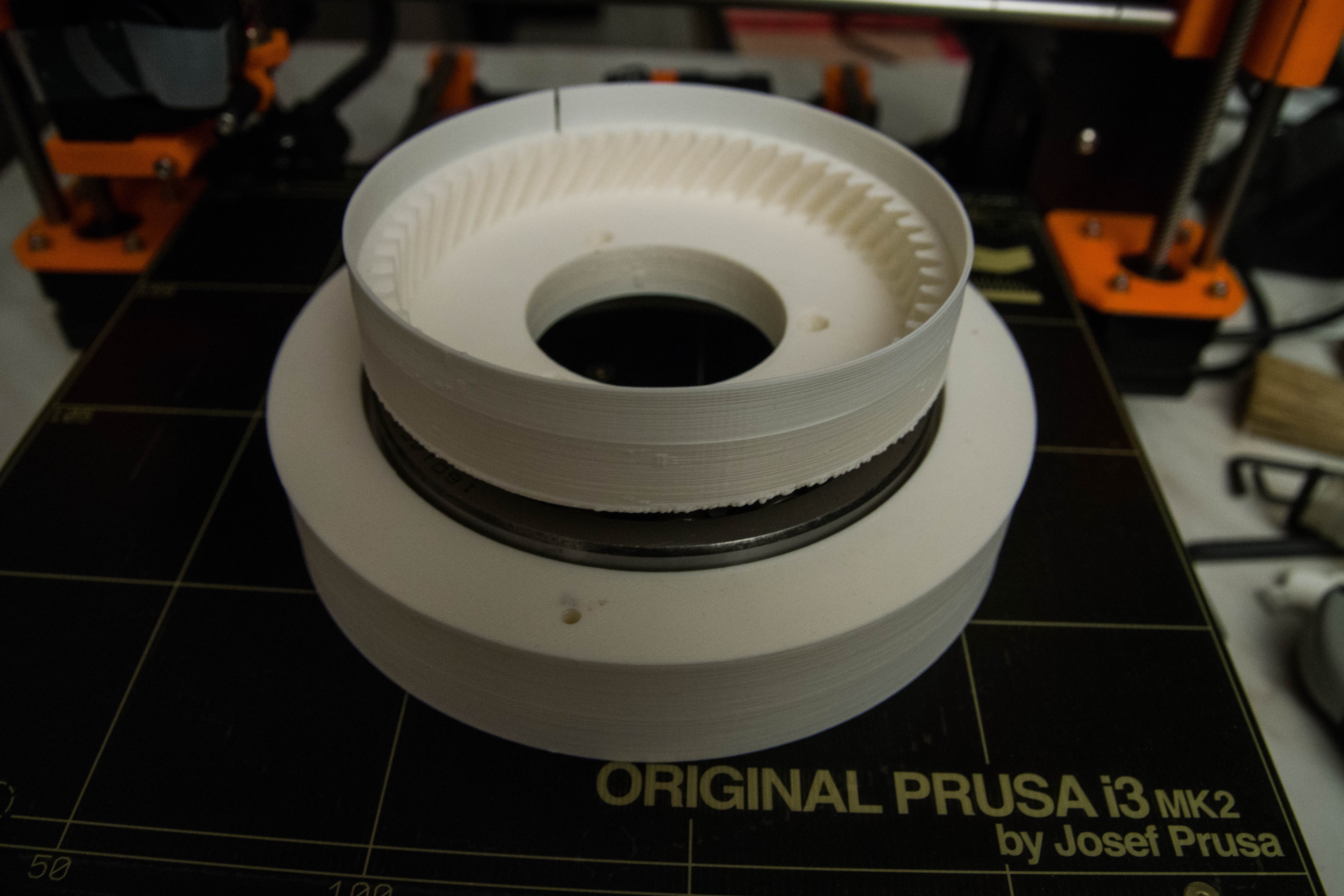
![]()
The bearing is intended to fit in BaseTop01. I noticed that it does not fit into the 3D print so I am guessing that I have to scrape off a bit of the plastic.
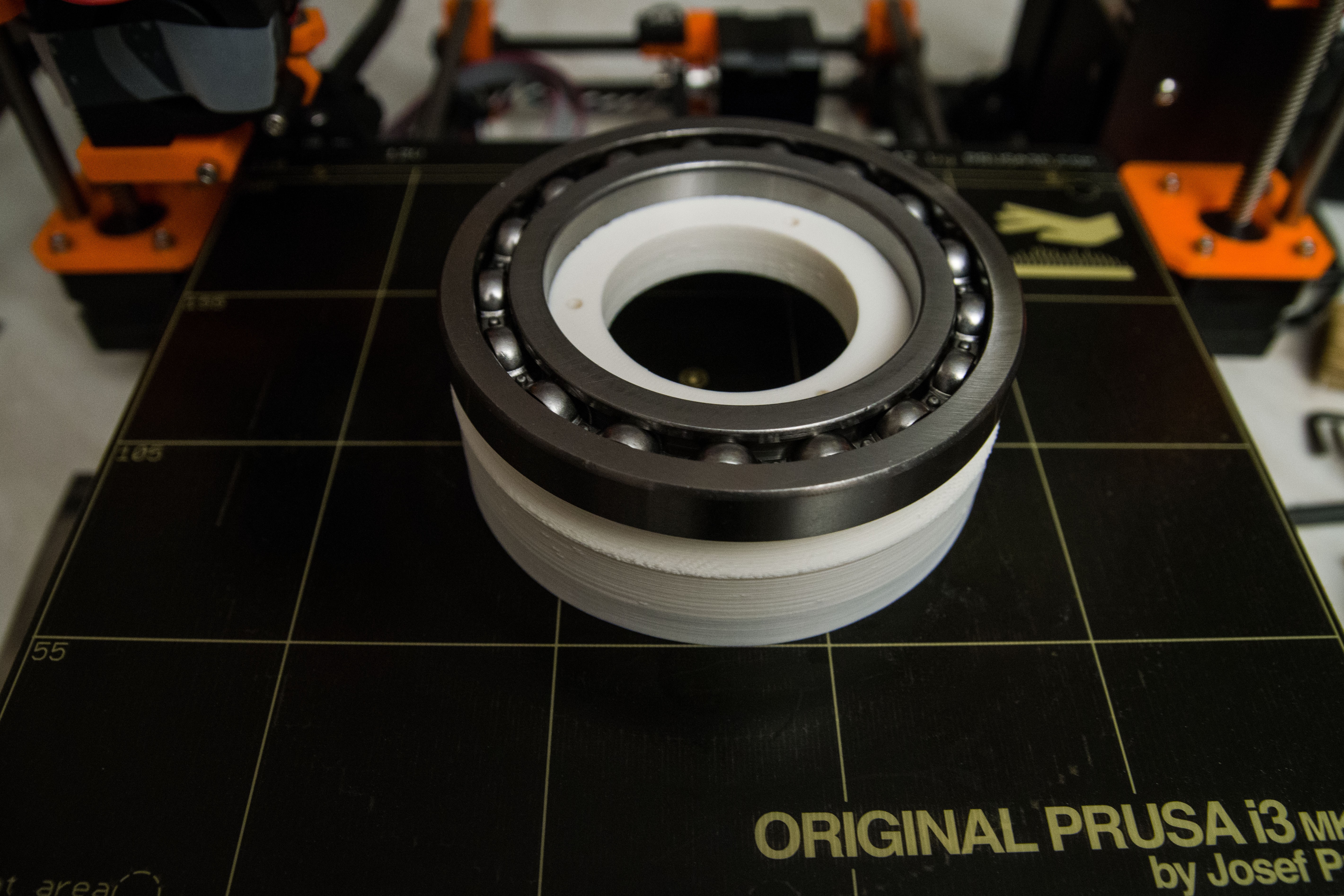
![]()
This part is upside down in the real Thor robot. Imagine that the ball bearing is fully inserted into BaseTop01 then Art1Bot fits into the inner hole (that one does fit). You can see the photo cell light split and the cogs that will be driven by the Base motor.
As Danny warned me, it should be painted black otherwise the light detector will get wrong signals because the plastic is transparent. Thanks Danny!
Art1Bot again but this time in the correct orientation.![]()
![]()
Partially lose assembles as a trial to get an idea how it is going to be assembled once I get the ball bearing inside the 3d model. I have some scraping to do.
The Base print is from Danny's model that already has cut out parts in the base for a controller and wires.
One remark, I have noticed that the base stepper motor draws 2.2 Amperes. I think we need some holes in that base part because I expect it to be getting hot.
-
Controlling 7 stepper motors, new ideas
01/03/2017 at 18:40 • 0 commentsI know there are several good solutions out there to control stepper motors but this part of Thor to design is mine.
The robot should be able to move like a human would, and not like a machine. This one I design from scratch.
The goal is this:
- Fluid like human like motion.
- Stepper motor accuracy, every micro-step counts!
- As fast as possible, without breaking the robot or kill the payload.
- Safety without compromise.
The initial idea is to have a count down counter for every single stepper-motor that generates the needed pulses. You set the value then go and wait until the counter reaches zero.
But this gives a big issue because the intention is to have a fluid motion of all 7 of the stepper motors. In order to do that, then I would also need to control the counter clock of each of the 7 motors individually. This may be harder to do than expected.
An alternated way is to have one byte control all 7 stepper motors step commands. Every clock pulse means that all motors move at the same pulse. (Note we may need to change that with a shift register to prevent voltage drops)
We will use a lot of memory but every stepper motor steps can be per-programmed in memory so and therefor can move at different speeds. The whole purpose of this is to have the one part that controls the motor as simple as possible.
This also separates the code that determines the positions form the actual motor control. And in addition can slow down the motor speed.
Can this be done? I have no idea, and that is why we are going to try this.
-
Ideas to speed up the 7 stepper motors
01/02/2017 at 18:29 • 0 commentsThe Ultrasonics v1.0 board comes with a fast processor ( 32-bit Atmega SAM3X8E clocked at 84Mhz).
![]()
It also has 7 sockets for separate Pololu DRV8825 Driver Carriers.
But this processor may not be fast enough for smooth stepper-motor control.
So I have an idea to modify the electronics part so that the "step" signal could be controlled by a hardware pulse generator that counts down the number of steps. This would free the main processor to prepare the next stage.
We will need some mechanism to abort the planned steps in an emergency.
I believe that a fluid moving robot is what what makes the difference between a toy and a robot that has character.
Just some wild brainstorm.
-
Setting up of Visual Studio 2015 instead of Arduino Sketch
12/31/2016 at 14:09 • 0 commentsArduino Sketch is a nice tool, but when you want to create a more complex program, then Visual Studio 2015 is a great solution.
I installed Atmel Studio 7.0 but that one was as buggy as hell so I removed it again.
First of all you must have Sketch installed before you continue these steps. The plugin needs the Arduino Sketch installed.
Also you must have Visual Studio 2015 installed.
Go to "Arduino IDE for Visual Studio (plugin)"
Install that one.
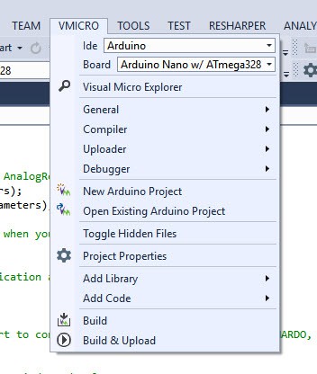
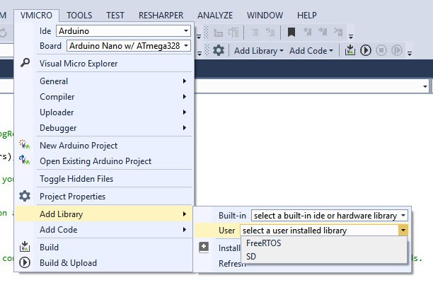
Now Visual Studio has this new menu item: VMICRO
![]()
You can select the board, add Arduino libraries, build and upload to the Arduino board...
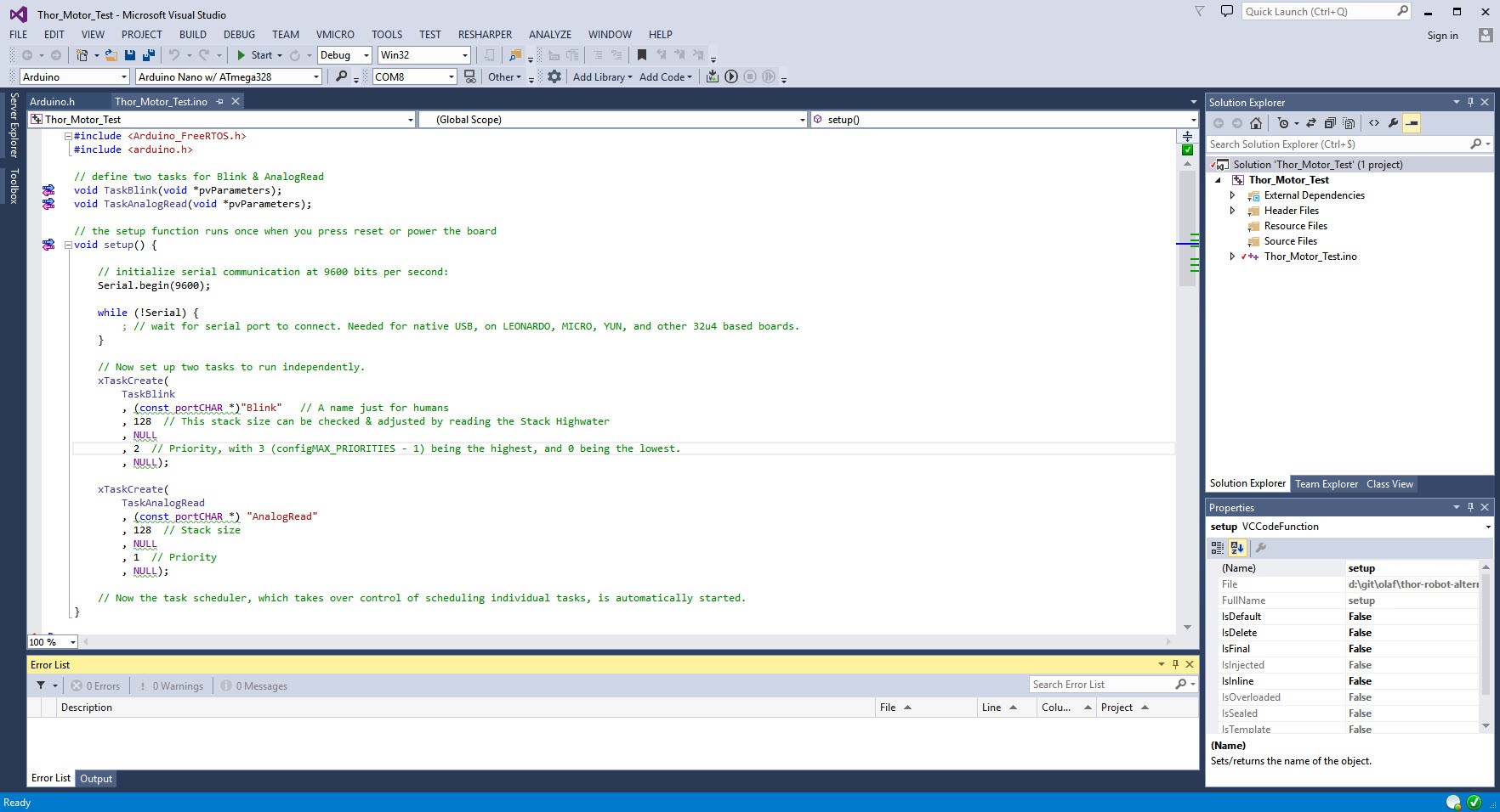
![]()
You can edit your projects as you normally would but with a powerful editor.
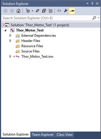
![]()
The Solution explore in Visual Studio 2015
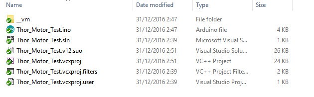
When you go the Windows folder then you see this. (Notice the "Thor_Motor_Test.ino" file that can be opened normally by Arduino Sketch).![]()
![]()
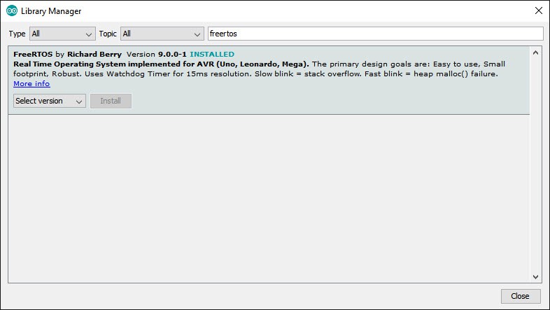
Because we want to use FreeRTOS, we have to tell the Visual Studio Arduino plugin that we also want to include the FreeRTOS.
We are now ready to start developing.
-
Controlling the 7 motors: Installing FreeRTOS
12/31/2016 at 13:49 • 6 commentsThanks to Danny I discovered FreeRTOS that probably will make controlling the 7 stepper motors fluently. It is a small "Real Time Operating System" (RTOS) designed for small devices.
I went to the FreeRTOS web site but when I unzipped the files, I did not find a Arduino Sketch version.
In the end I found out how easily you can install it from Sketch itself.
Open Arduino Sketch
Go to menu Sketch --> Include Library --> Manage Libraries![]()
You now find a list of libraries you can modify, update and install.![]()
Search for freeRTOS, and you will find it. Click on it and you get an install option.![]()
Once installed you are ready to go.
The source code fro that Arduino version is coming from: https://github.com/feilipu/Arduino_FreeRTOS_Library
-
First trial with all the stepper motors
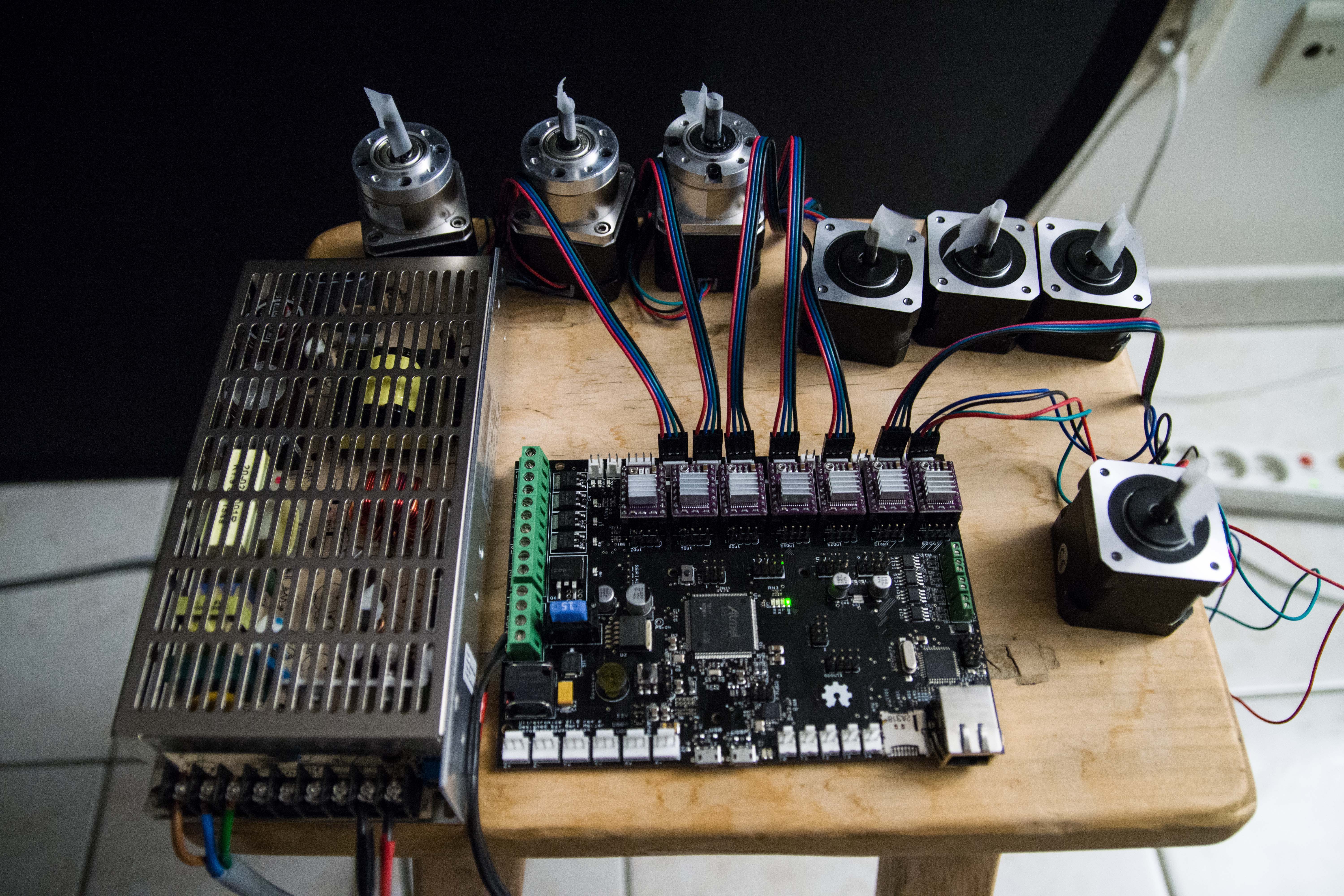
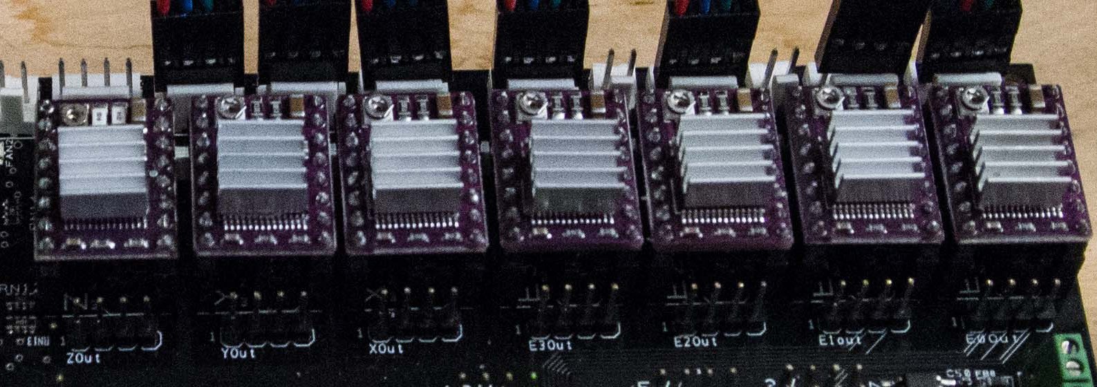
12/30/2016 at 03:00 • 3 commentsI finally have all the components to test the complete electronics board with all 7 stepper motors. And they work!
![]()
The top 6 of motors did not have a connector for it, so I had to solder it with a cable I purchased from RepRapWorld (4-wire cable 24AWG, Red Blue Green Black (1m)). But I had to make sure that red and blue should be swapped for these motors from StepperOnline.
Those 6 motors needs 0.4 A so the DRV8825 is overkill, but the motor in the middle right has to rotate the complete base and that one will draw 2A and needs a DRV8825. This DRV8825 heats up a lot and probably needs a fan to actively cool it.
The decision of using DRV8825 is purely based on having swapable modules because they are all the same. And for future projects that can have bigger stepper-motors.
The DVR8825 I purchased from RepRapWorld (€12 no heat sink) but also from Xcsource (10 for €22 includes a heat sink) and they both appear to function very well. But from Xcsource it took 3 weeks to deliver. I was convinced that they would never arrive, that was why I ordered 3 more from RepRapWorld
Next step is the most challenging part. I want all 7 motors to work fluent and fast. I have doubt that the Arduino language is powerful enough. Here I will deviate from the Thor and Danny's project and design my own version.
-
More assembling (Art2Bodies and Art3Body)
12/29/2016 at 01:59 • 3 commentsToday I was a happy man since I finally received the very long m3x50 screws and the 6 mm balls for the 3D printed ball bearings.
To hold the 2 Art2Bodies together it requires 8 very long M3X50 screws and nuts.![]()
The upper part will have one metal axis, the lower part that drives the cogs will actually be 2 small axis endings that will get pressured in place by the midsection. I did had doubt this part would function well but now that I have the midsection assembled I am convinced that it will work.
I also received the 6mm balls for the 3D printed ball bearing for Art3Body. So I could assemble it.![]()
(Note: This part has been photographed upside down to show the cogs)![]()
Detail of Art4TransmissionColumn assembled with the 6mm balls that gets inserted through the hole (left side on the image). Once this part is inserted into Art3Body, the hole gets covered. However I put a piece of paper to block the entrance because I don't want the balls to drop when I disassemble.
-
Powering up the Ultratronics v1.0 Pro
12/27/2016 at 01:57 • 0 commentsI am moving at a slow pace because I have a lot of learning to do with stepper motors and the Ultratronics v1.0 Pro controller board.
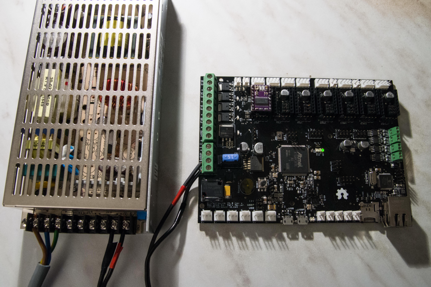
The documentation of the Ultratronics v1.0 Pro is yet again confusing. When I bought it, then it states that it supports both 24V and 12V power source. I want to go to 24V.
But when I got it in my hands,it has 12V written on it and the documentation talks about a 12V jumper to set.![]()
The confusion is that there is also a second heat-bed power source intended for 24V and then you start to doubt if they mean a 12V power source for the motors and controller + second 24V power source for the heat-bed only.
The last thing you want to do is fry the controller with 24V source while it only accepted 12V source.
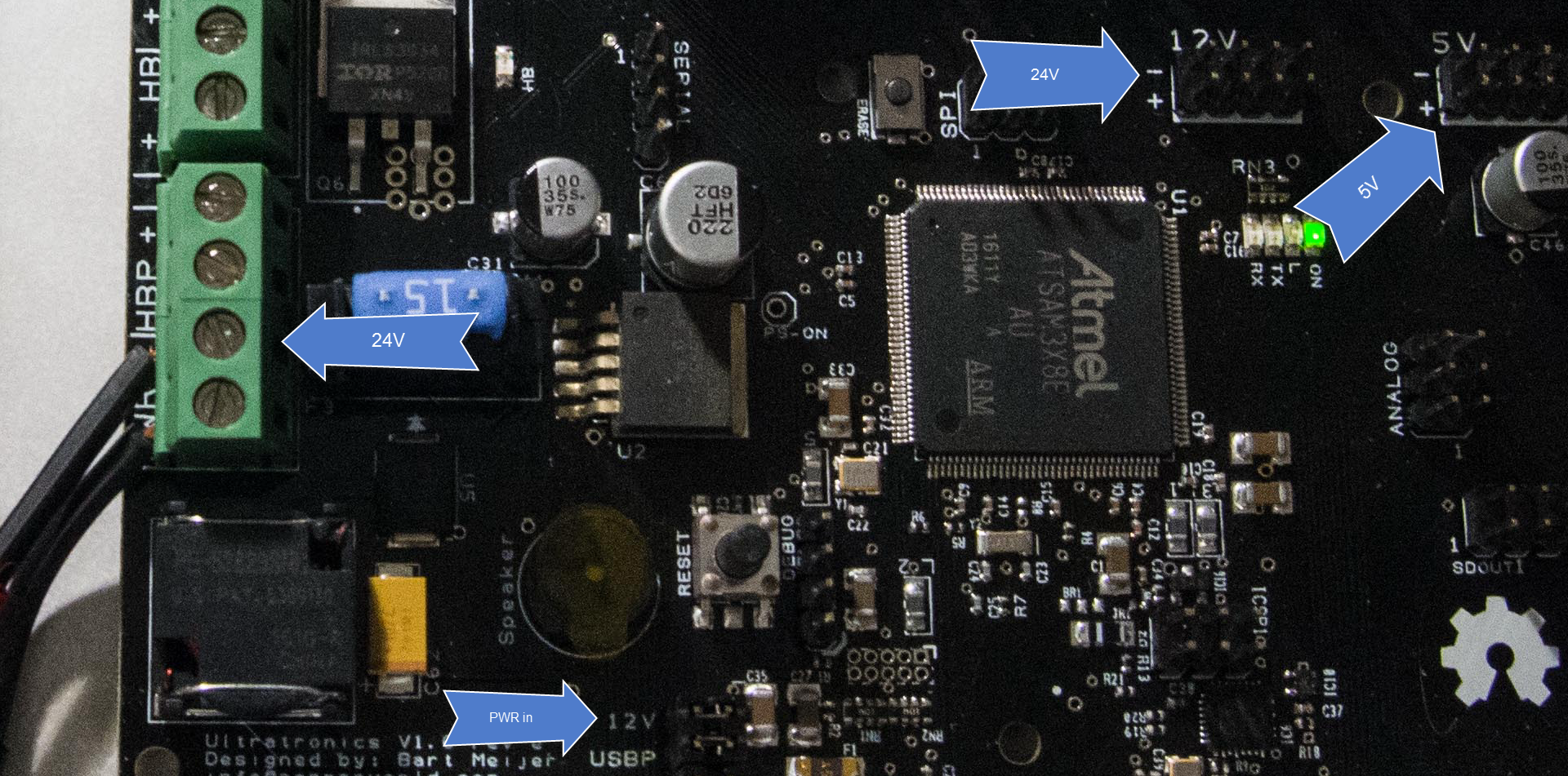
![]()
Rereading the documents did not make more sense so I took a gamble.
Because they talked about a 12V jumper, I removed the 12V jumper (below in the image)
Then wired up for the 24V input source. (I am not using a Heat-bed for this project) so I did not wire this one up. I powered the source on and nothing happened. No lit LED.
So I cut the power, connected the USB cable and happy to see that the controller still worked and I did not fry it.
Rereading the document several times over made me assume that the 12V jumper is not a switch between 12V and 24V but a choice to use power from the "power in" source or not.
It would have been clearer if they did not call that jumper "12V" but "Power in". Because I feed it 24V not 12V.
The documentation did state that when I use 24V then I must hook up devices that can support 24V instead if 24V. Measuring the headers that are marked 12V on the board actually now has 24V on it.
Whoever the headers that have 5V and 3.3V does have the correct 5V and 3.3V.
Building the Thor robot
Building a 6-axis robot based on the Thor robot. When size DOES matter!
 The only way where you get a robot moving like a ballet dancer is when you control those those stepper motor as one entity. They must act like one entity in perfect synchronicity.