This is a first design for the instruction set. In the final computer, the instruction set could be changed any moment by putting a new microcode in the Flash microstore.
This instruction set borrows from the 68000, PDP-11 and SPARC !
Here are the registers:
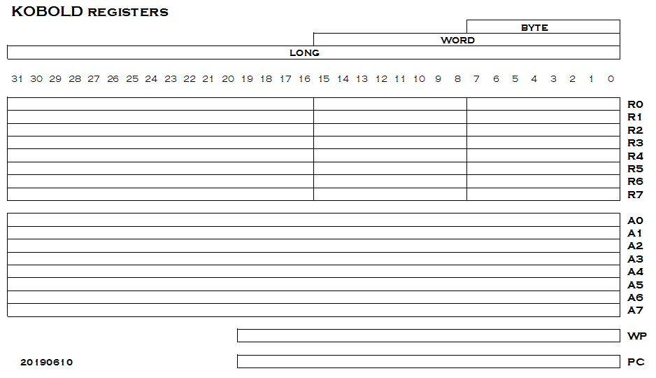
The register set R0 - R7 has general registers, they can be used as data or address registers, comparable to the registers in the PDP-11, but in this case the registers can also contain 32 bit data. They are located in memory. There can be many of these register sets, and the WP register points to the current register set. A called function does not have to push registers, it simply changes WP to get a fresh set of registers.
The registers A0 - A7 are global address registers, located at a fixed position in memory. Each of these registers can point to a structure (of 8 words max). The elements of such a structure can be read or written with a single instruction.
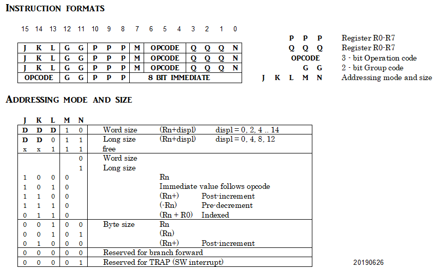
All instructions are 16 bit, as follows:
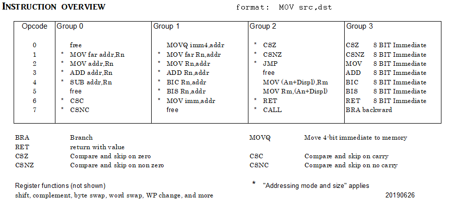
And the overview of instructions:
A few remarks:
- All addressing is within 32KWords, except for the "MOV far" instructions that address the full 1 MByte.
- CALLS, JUMPs and RET are within 32KWord for word size, and use full 1 MByte destination for long size.
- On this level, there are no flags. Conditionals are done with compare-and-skip instructions. The skipped instruction can of course be a branch (with 7 bit value). Skipped instructions should not have immediate values following them, of course.
- Branches forward have the upper 8 bits zero, and branches backward have the upper 8 bits ones. A branch is done by simply adding the 16-bit instruction to the PC.
- Return instructions include a function-return value (an 8-bit immediate or any other value).
- Moving an immediate value to memory or adding a register directly to memory is supported. For 4-bit values, this moving is a single 16 bit instruction that includes the 4-bit value.
- The "indexed" addressing mode will add two registers to calculate a source or destination address, then do the requested operation, all in a single 16 bit instruction.
- In byte-size mode, The (R) or (R+) addressing modes access bytes in the lower or upper half of a memory word (depending on the lowest address bit), to access arrays of bytes.
- There are no memory-to-memory instructions (as in the 68000 and PDP-11). These might be emulated by letting the assembler generate two instructions.
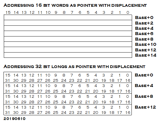
It is expected that the "pointer + displacement" address mode will be used a lot. Note that the displacement is OR-ed to the address, so the address needs to be proper aligned. The following picture illustrates this addressing method
This is a rather ambitious instruction set. Perhaps it will be simplified if it is too much work to implement.
I am open to suggestions !
PS Several decoding details changed today (20190629).
Discussions
Become a Hackaday.io Member
Create an account to leave a comment. Already have an account? Log In.