 Marcos
Assembly basics
For several months we got the electrical assembly figured out, and its good and simple for evaluation (Imagine a company looking forward to introduce this controller into its production line).
This greatly reduces the assembly time, and its literally a bolt-on solution to these high power IGBT modules.
The point of this basic, enclosure-less assembly is to let customers test this system on their dynos, with their motors. Its purposely open framed for easy access to testpoints, coax connectors and LEDs; it must be easy to work with.
This same concept is helpful for one-off builds, as those will likely require some debugging and double checking of everything.
Fully enclosed version
As cool as it is, its certainly not enough to convince a big customer, they need a few basic items to take Axiom seriously:
- An enclosure, and most important the assurance we can customize it to their mechanical requirements
- IP67+ ratings
- Marketing material
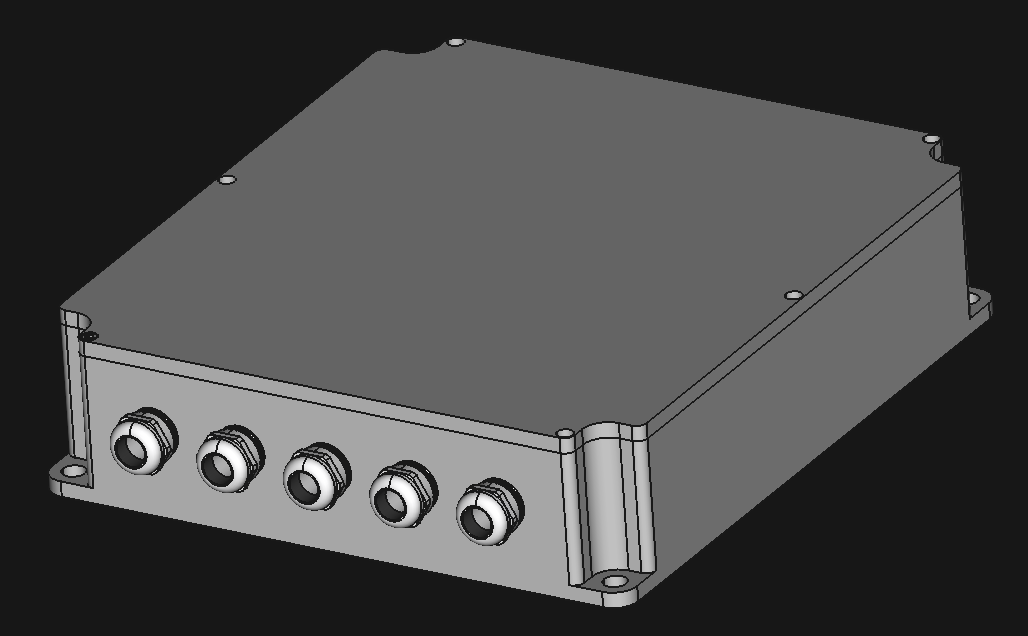
Enclosure design
We chose to make a fully parametric enclosure design, in order to easily make changes to support different mounting arrangements. Due to EMI and IP ratings the material is most likely aluminum, and since upfront tooling costs of a CNC job are way lower than plastic injection or die cast, its not unreasonable for a customer to spawn a new design. For a large production, aluminum die cast is an option, but you really need volume to make it the lowest cost option (thanks Eric for this tip at the mentorship session).
The design is of course made in FreeCAD, a multiplatform, open source, no hassle and powerful MCAD tool. It also has a particularly good integration with KiCad.
We had some requirements for the enclosure:
- IP67 (actually aiming for IP6K9K) with off the shelf o-rings
- Full shielding for easier EMC compliance
- Integrated liquid cooling
- Experience told us that High Voltage connections must be on the same side
- Easy service
- Compact
- Nice looking for marketing
To get the enclosure looking like this, we made custom busbars for the phase outputs, a custom laminated dc busbar to reach the DC link with minimal EMI inside the enclosure, proper sizing for the coolant ports and keeping in mind this has to be machined in a 3 axis CNC, so there is some design for manufacture going on here like minimizing the milling surfaces to 4 (top surface, bottom surface, HV connectors side, los voltage signal side).
Integrated liquid cooling would be a major cost saver here, as the coldplate we currently list in the BOM costs around $300, we could have the whole enclosure made for that money. Its also an awesome place to spend Axiom's award of $500 for finishing first in the Hackaday Prize Bootstrap stage.
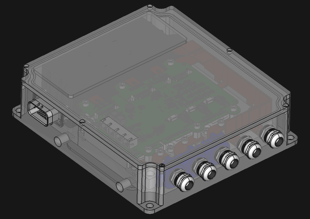
Lid off! showing some internals:
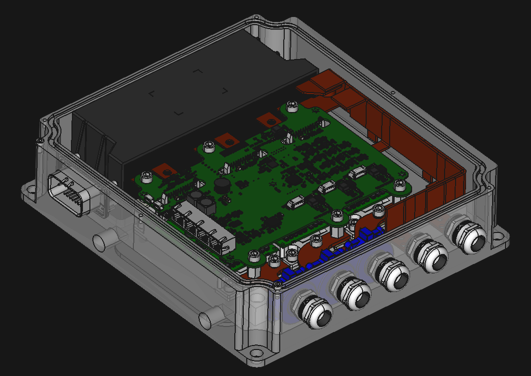
Have you heard about semi-transparent aluminum? Me neither, this is just a CAD transparency setting.
Going for a tidy and minimalist design:
The mechanical design is not ready, "Mechanical, part 2" will be about the design of the enclosure belly, which is responsible of the cooling performance of the motor drive because it includes the coolant channels and pin fin design below the IGBTs, which requires optimization of pressure drop vs thermal flow from IGBT to the coolant. If anyone knows how to do this FEA in FreeCAD, it would be most welcomed!
Its really cool that fully open source tools like KiCAD and FreeCAD get you this far into product development.
The great news is that we are arriving to the final exterior look and feel, that means we unlocked a major road block for marketing development!
Discussions
Become a Hackaday.io Member
Create an account to leave a comment. Already have an account? Log In.