The Allwinner V3s provides 3x UARTs (UnAsynchronous Receivers / Transmitters): UART0 with only RX and TX signals, and UART1 and UART2with additional RTS and CTS flow control signals.
As almost all SoCs, tha Allwinner V3s provides a serial console as a control terminal for debug or normal operation. By default, it is mapped to UART0, and it is used by the BROM (Boot Rom), the U-Boot bootloader and by the Linux kernel to output messages during the boot process, and later by the Linux kernel to log messages during normal operation. Depending on the configuration, it can be used too for loging into the system over an UART.
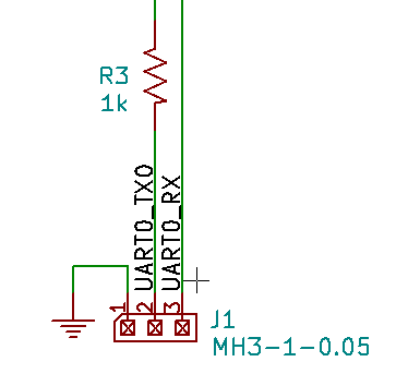
The Console schematic only requires a minimum of external components:

Besides the 3-pin 1.27 mm (0.05") pitch header J1 that will not be mounted on standard products, there is only a single series resistor R3.
What is the purpose of this resistor?
- As explained previously for the SD Card clock signal, this may be to prevent ringing. But given the relatively slow signal speed (115200 bps), it is not the case here
- If it were placed on the RX input signal, this could prevent frying the input pin if a large voltage (+5V, for example) is applied to it by dissipating the excessive voltage as heat in the resistor. It is not the case here, since the resistor is on the TX output signal, but we could have one added, if only we had some space left on the board...
- In fact, the resistor is on the output TX signal to prevent short-circuits if the serial cable is reversed and the 2 TX outputs are connected together, one driving the signal low, while the other is driving it high: again in this case, the voltage difference between the 2 outputs will be burned as heat in the resistor, saving the output buffers!
Note that there is no ESD protection TVS diodes: this interface is not supposed to be mounted in the final user device, and PCB space is really constrained in this area, so they are omitted.
 Squonk42
Discussions
Become a Hackaday.io Member
Create an account to leave a comment. Already have an account? Log In.