Capacitor Usage
So far, we already encountered capacitors for many different usages:
Load Capacitors
We have seen load capacitors used with the 2 crystals in the discussion about CPU.
A quartz crystal always provides both series and parallel resonance, the series resonance being a few kilohertz lower than the parallel one.
Crystals below 30 MHz like ours are generally operated between series and parallel resonance, which means that the crystal appears as an inductive reactance in operation, this inductance forming a parallel resonant circuit with externally connected parallel "load" capacitance. Any small additional capacitance added in parallel with the crystal pulls the frequency lower in the range between the series and parallel resonance frequencies, insuring crystal startup and stable operation.
For modern circuits, these load capacitors have a typical small value < 20 pF.
Bulk Capacitors
Bulk capacitors are used to prevent a power supply from dropping too far during the periods when current is not available. At the same time, they help to reduce the power supply voltage ripples by smoothing their output voltage.
Many such capacitors are used at both the input and output of the numerous linear and switched mode power supplies in the PMIC discussion.
The main bulk capacitor value is generally high (some µF), but there may be smaller parallel capacitors added for stability.
Coupling Capacitors
As you probably know, capacitors are made of 2 parallel conductive electrodes separated by a (thin) isolating dielectric material (even if these electrodes are rolled or layered to reduce the component size). Thus by construction, no DC (Direct Current) can flow from one electrode to the other, but by influence using the electric field, AC (Alternative Current) still can go through. This is how coupling capacitors are used to link 2 circuits while removing any DC bias voltage on one side or the other of the capacitor.
We use such a coupling capacitor in the Audio schematic description for feeding the audio power amplifier from the CPU audio output.
Filter Capacitors
We have seen many examples where capacitors are used within passive filter circuits along with resistors or inductors, mainly to remove unwanted frequencies from a power supply or a signal.
Decoupling (Bypass) Capacitors
We have already seen some decoupling capacitors when looking at the buttons circuit.
Active components such as transistors and chips are connected to their power supplies through conductors featuring a (small) common impedance made up of complex (resistive, capacitive and inductive) value. Because of these parasitic components, a device that suddenly draws some current in spikes will generate a drop in its voltage power supply. If many devices are sharing the same power supply and impedance, the state of one device will be coupled to the other ones through the common impedance of the power supply conductors and may affect thir operation.
In order to decouple the devices, capacitors placed as close as possible to the device power supply input pins are used, which act as local energy storage. These capacitors are also named "bypass capacitors" as they shunt transient energy from the power supplies past the device to be decoupled, right to the GND return path.
There may be different capacitors values placed on the same power supply pins in order to filter transients at different frequencies: the bigger the capacitor value, the lower the frequency. A typical value is 100 nF, and values from 1 µF to 10 µF are used for lower frequencies and / or higher current draws, while lower values of a few nF are used for filtering higher frequencies.
In essence, decoupling capacitors are not very different in their function from bulk capacitors: the only difference is one of scale, both of current and of transient duration. Bulk capacitors deal with large currents and periods of 10s of ms, whereas decoupling capacitors are used for much lower currents and much briefer periods (typically 10s of ns for TTL or CMOS devices) .
Schematics
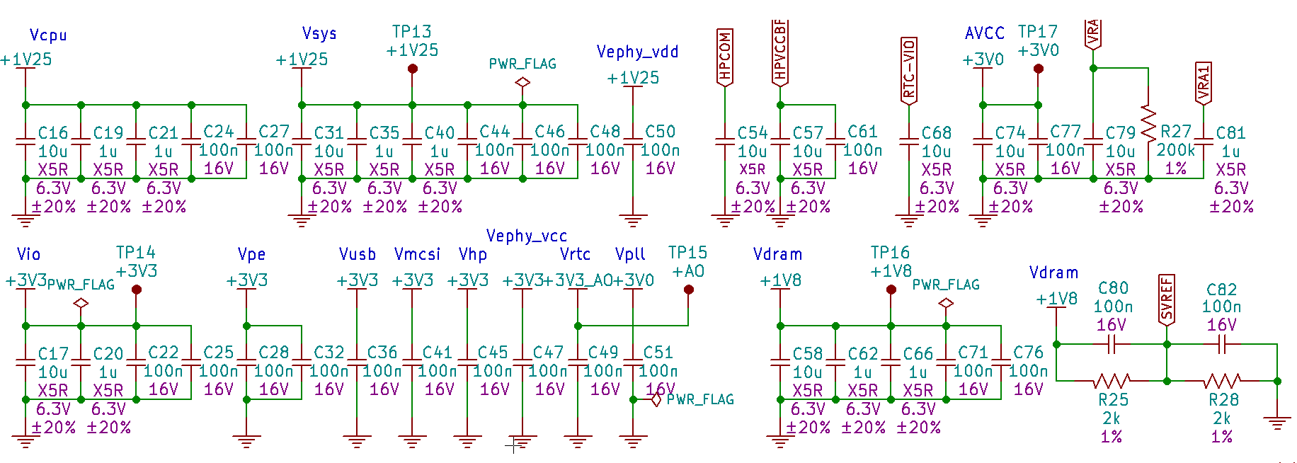
The last part of the FunKey schematics merely contains only decoupling capacitors:

One exception is the Allwinner V3s CPU HPR/HPL circuit which features an RC-to-ground circuit between the amplifier and the preamplifier input with the resistor R27 and capacitors C79 and C81, as recommended in the V3s hardware design guide.
The only other remarkable point left in this schematic is the resistor divider R25 / R28 which provides a reference voltage at half the DRAM power supply voltage level, which is used for the integrated DDR2 DRAM merged drivers and dynamic on-chip termination already discussed at the end of the previous CPU schematic description.
Conclusion
This concludes the description of the FunKey gaming console electronic schematics. The full schematics is available in the design Zip file and in PDF format too.
As we have seen, the design is not overwhelmingly complex, but it contains many details that are all important to make sure the device works as expected.
 Squonk42
Discussions
Become a Hackaday.io Member
Create an account to leave a comment. Already have an account? Log In.