 CapitanVeshdoki
A little update here.
After some thinking I decided to change way how comparators are powered.
In previous version they were connected directly to PSU/battery, because supply voltage of a comparator determines range of permitted voltage of an input signal, however it seems what big input voltages aren't necessary here.
Then we measure current on coil we are interested to put as little resistance in serial to coil as we can, thus it would dissipate less heat and we aren't losing overall efficiency, and as a resistance is small - voltage, according to Ohm's law, would be small too.
Even if we forget about efficiency, it's hard to get 10+V from a MCU, so maximum 5V input voltage is a great choice here.
Also I added Hi-Z ground, because it's kind of required to measure voltage from a part of high-current circuit without even higher current leakage. So schematics now looks like this:
 It's time to fabrication, because PCB's are ready and they are even more symmetrical now! : )
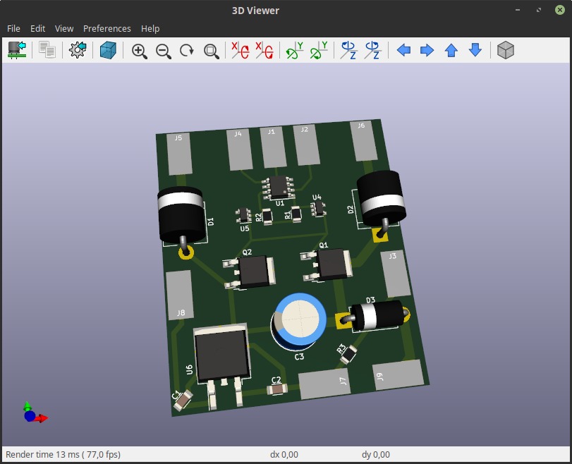 And after all I'll return to "How it works" once more, because now I drew more detailed graphs about it:
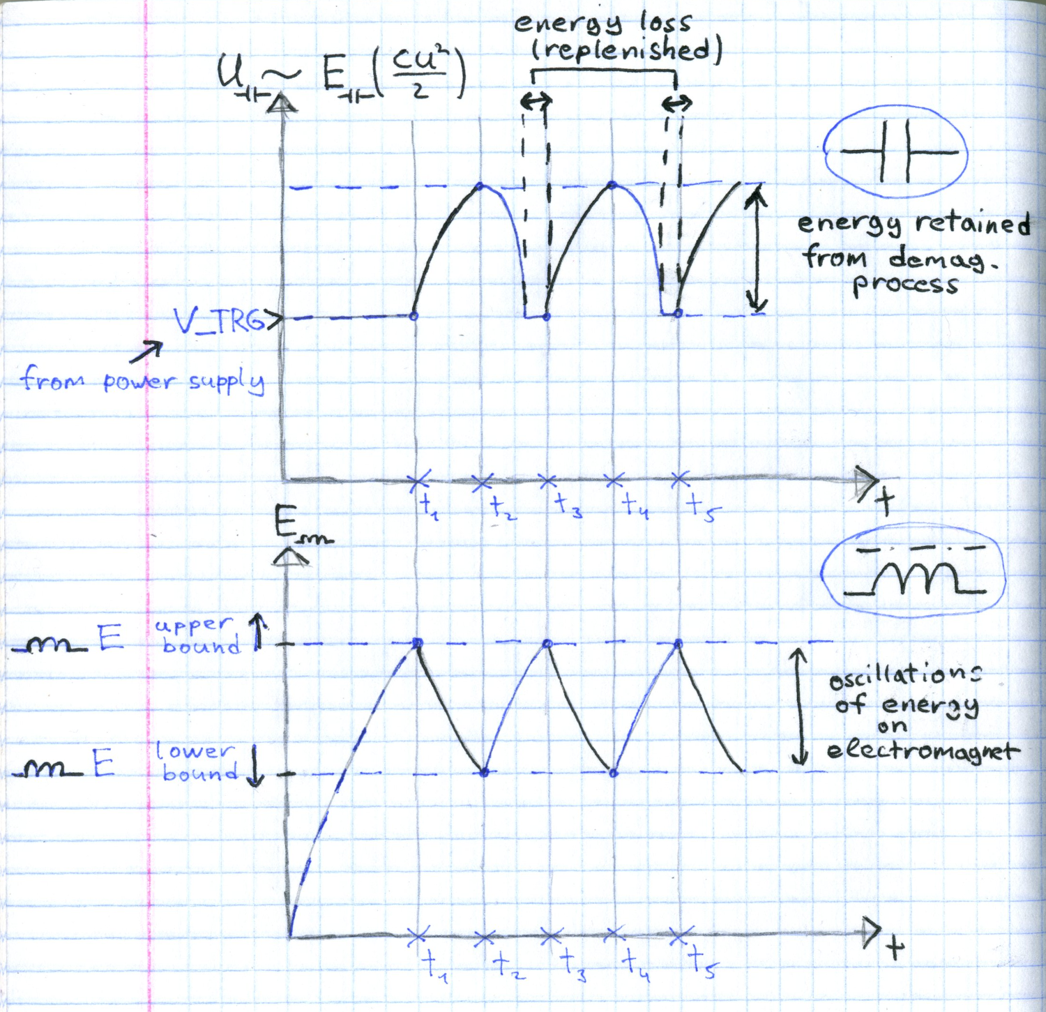 This is how this circuit should work. I'm very curious now, what is minimum amplitude of energy oscillations for this method, because it determines smoooothness. And also curious if I can connect this circuit to a conventional electric motor (though, it doesn't needs it very much, motors are different and they are already know how to use magnetic energy without dramatic looses, thanks to their rotating parts)
P.S. lower/upper bound E are defined by V1_REF and V2_REF, capacitor is a C3 on board
Discussions
Become a Hackaday.io Member
Create an account to leave a comment. Already have an account? Log In.