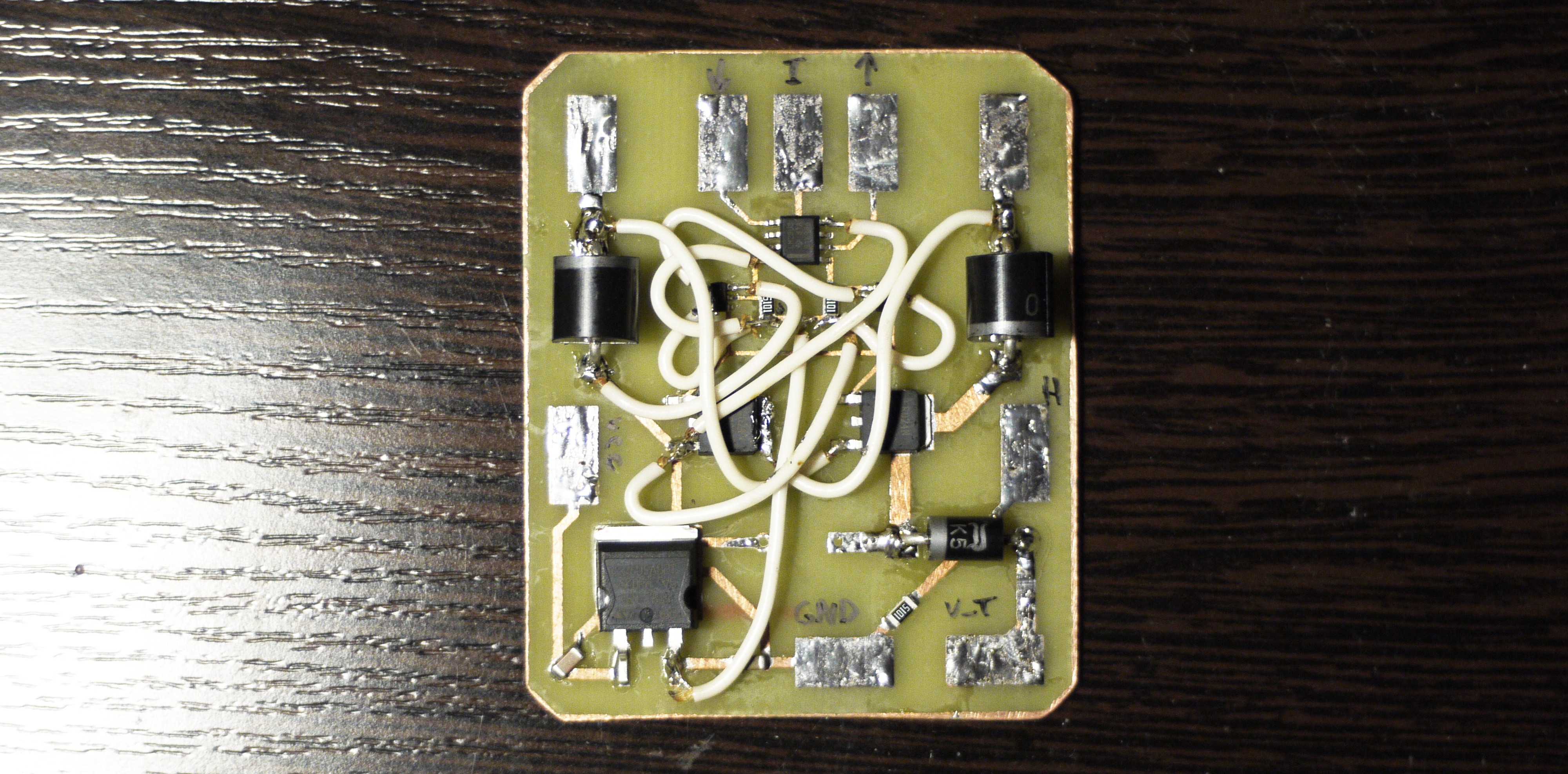
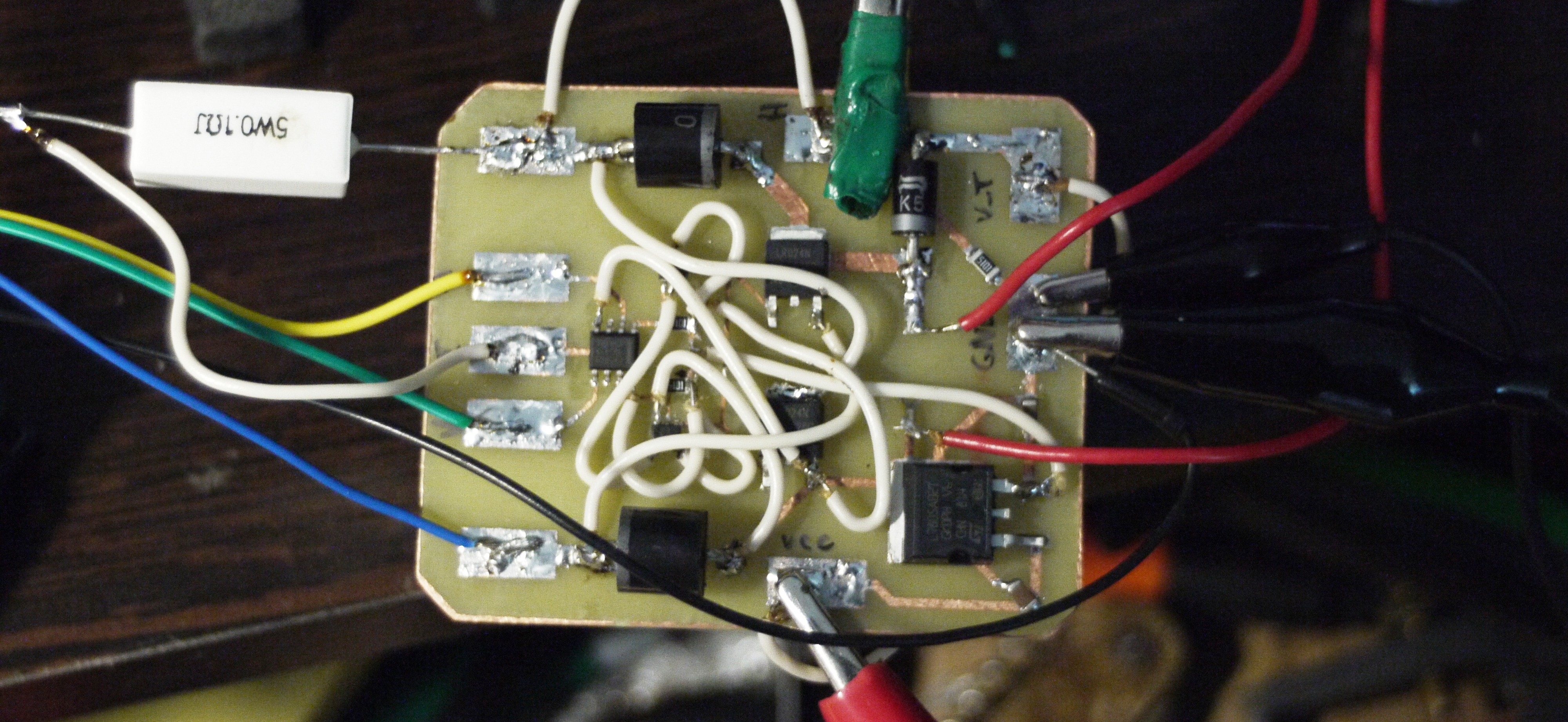
Yesterday, I managed to solder everything in place!
When everything connected it looks like that:
But then I realized what something went wrong. Well, board consuming 0 current (according to my 5A PSU analog indicators of course), I can feel a slight field around the electromagnet, but too little. Then I connected an oscilloscope (1ms/div): So there it is! This is a voltage which goes from S-R latch to the gate of transistors. So far looks not that bad (except of 30% duty cycle)
 And there fun things started! This is a voltage on I_COIL input which theoretically represents current on electromagnet, however... It is 10V/div, so as I tried to measure voltage on the 0.1 Ohm resistor connected in serial with a coil - this would mean, what in some time periods there is around 100 Amps. Looks pretty awkward, isn't it?
 Well, it is. Because then I connected oscilloscope directly to the resistor, there wasn't anything like that.
That means, that I must figure out how to measure current (representing energy of field) correctly without damaging energy-retaining process.
Trivial task, but It may require two independent grounds to prevent leakage of electrons. I hope it wouldn't be necessary (because I'm lazy! ahaha)
 CapitanVeshdoki
Discussions
Become a Hackaday.io Member
Create an account to leave a comment. Already have an account? Log In.