 CapitanVeshdoki
Hooray! I've managed to simplify circuit even more!
Choose of electric components is more reasonable now - main MOSFET in D2PAK package and stabilizer for 5V logic voltage in small DPAK package, as logic gates never consume too much.
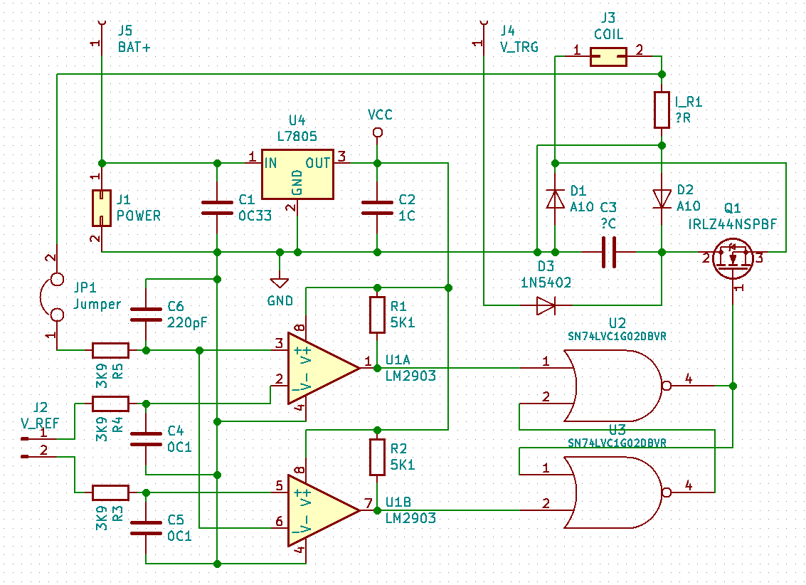
Here is how new schematics looks:
 New:
New:
- one transistor instead of two
- low-pass filters on inputs, it can use PWM output from a MCU
- as well, filters are helpful to suppress high-frequency noise
Still, it has all experimenting stuff - V_TRG isn't connected to BAT+, so it's possible to play with it (or place wire between them) and still there is a possibility to try another approaches to measuring current with help of jumper JP1.
PCB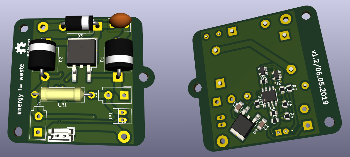 Around 5x5cm now, with mounting holes
Now it's time to fabricate it and check everything, but I'm pretty sure what it should work, because previous version worked as needed:
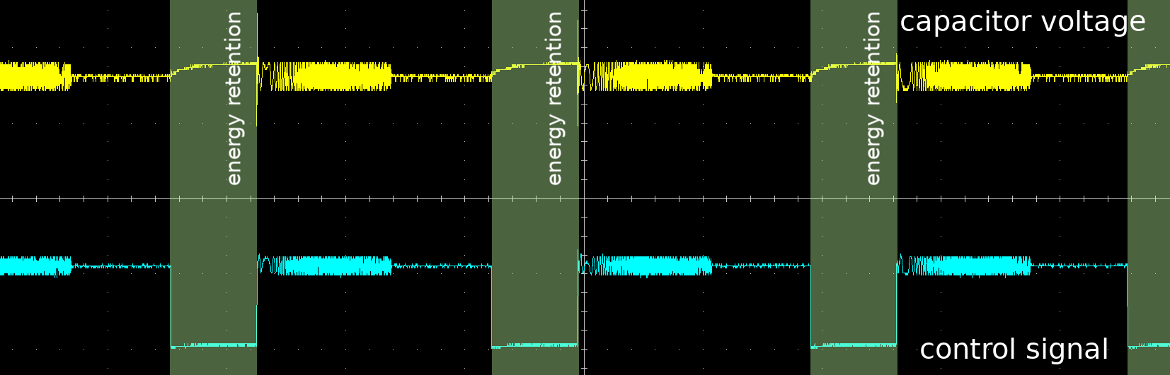 And there is only one major change in schematics (of course, previously there were two transistors, but anyway, C3 is connected to ground on last PCB and D2 was connected to ground in experiments manually by wiring, while I was working onto question how to read current on electromagnet properly),
 I've thought about flow of electrons here for some time and I can't find any flaws in new design, happily :)
Discussions
Become a Hackaday.io Member
Create an account to leave a comment. Already have an account? Log In.