The hunt for a fitting linear actuator, that was both reasonably priced and shipped fast took a little while, but the team settled on a IP66 PA-04 model from Progressive Automations, the 6" stroke, 100lbs, 2.80"/s to be precise, which fit Laurent and Sam's initial calculations. Two of them were ordered.
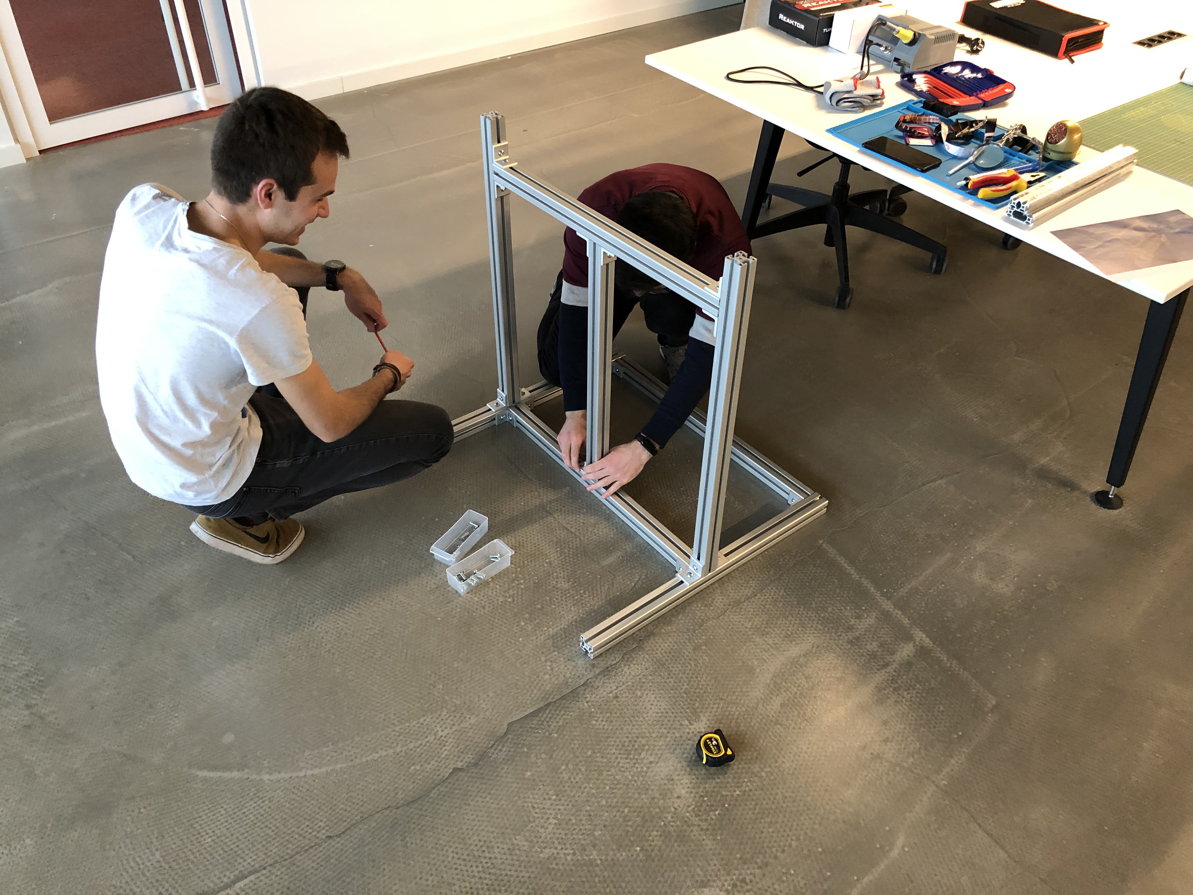
In the mean time, they build the test bench out of 40x40 aluminium extrusion, with a ball bearing carriage to attach the leg to.

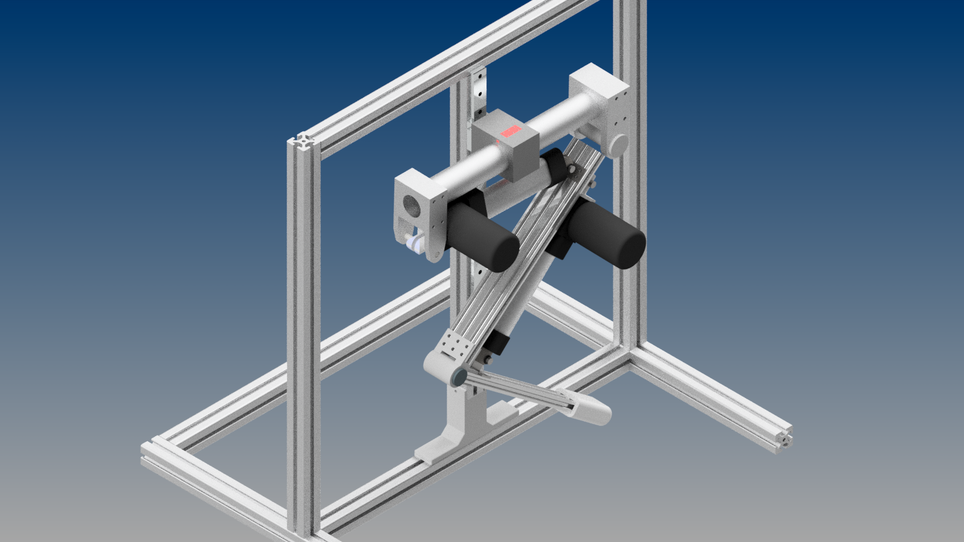
They also remade the CAD for the leg with the corresponding linear actuators, and designed all the joints and various other parts to be printed on the TAZ6 in nylon.

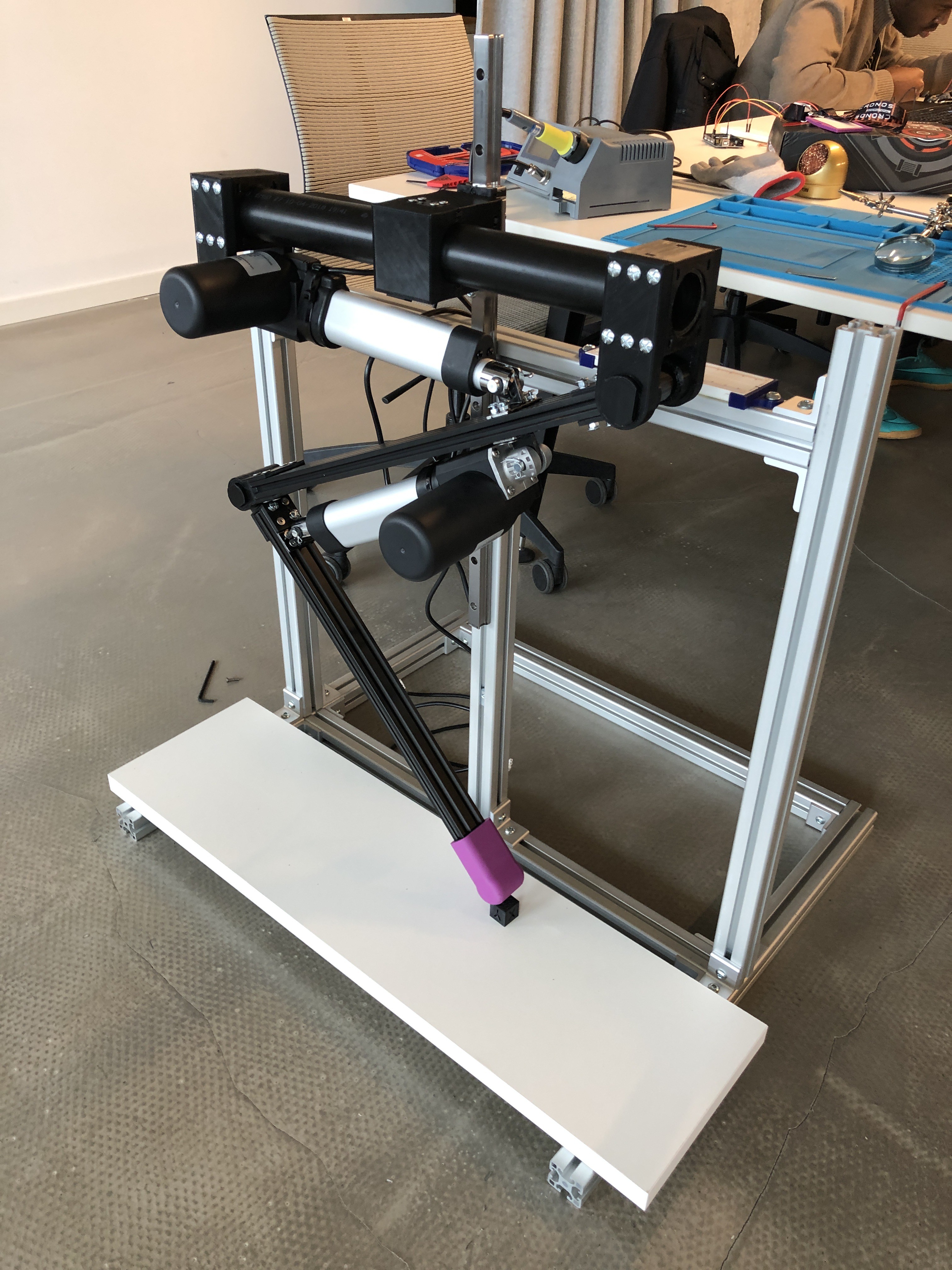
The leg itself makes use of two aluminium extrusion beams, a 40x20 for the lower part and a beefier 60x20 for the upper leg. The knee joint is all nylon for the prototype, but like most 3D printed part it will be upgraded later to machined aluminium most likely, with either a copper axel or ball bearings. The leg is mounted on a 50mm diameter tube, itself attached to the carriage on the test bench.
It will be controlled using an Arduino Mega, and powered by a 5000mAh LiPo battery, and using an AMT203 Encoder to measure rotation.
The team manage to assemble a first version of the leg, but the actuators turned out to be longer than what the spec sheet on the website advertised, which means the 300mm aluminium extrusion beams were too short.
New ones, 500mm ones were ordered instead, to be cut if necessary once they can validate the assembly.
After hours of printing and waiting for stuff to arrive, this is the result:

Currently, the guys are working on finalising the hardware on it. Due to being a bit behind schedule, the team settled on a PVC 50mm tube to carry the leg, which is proving to weak and slippery. Upgrades are being made, while Daniel started on the wiring, designing a new foot with more grip, using a flexible rubber like filament, while Laurent is running software test on the Arduino board.
Discussions
Become a Hackaday.io Member
Create an account to leave a comment. Already have an account? Log In.