 Miroslav Zuzelka
We made one board working and now, when I know what I did wrong, it is time for new revision.
I added missing pull-up resistor for RESET line for the OLED screen and looked again on those 2 schematics which I mentioned before. I decide to go with SeedStudio connection scheme, because there is SD card already in use (do not know if is used also in camera code example). I also changed reset button, because it was highest part of the board and I do not like that. I changed FPC connector as well, because it was difficult to find one which will match PCB footprint. I used Molex connector because I could find it in some Eagle library and also because 3D model is available.
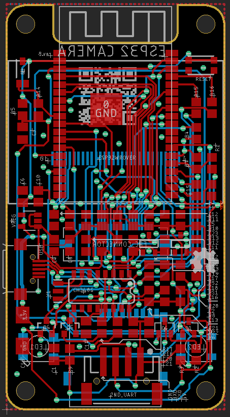
You can see here how board is routed:
Here is top & bottom side of new version:


Here is 3D animation:
New version is finished and I will post new log as soon as I assemble one or more boards. Stay tuned.
Discussions
Become a Hackaday.io Member
Create an account to leave a comment. Already have an account? Log In.