 Alan Green
BlueBoard#01 is...
A 100mm by 100mm board that's for prototyping and one-off projects that use SMT and through-hole components.

Features
- 19 standard footprints
- 2 x 1.27mm pitch footprints (10 pads, 28 pads)
- 1 x 0.65mm and 0.635mm dual-pitch footprint (28 pads).
- 1 x 0.5mm pitch footprint. (10 pads)
- 6 x SOT23-6, 3 x SOT23-8 and 4 x SC70-6 footprints
- More than 1000 square pads with 0.1" spacing and plated through holes
- Easy mounting of all two terminal SMT parts, and many three and four terminal parts, too.
- Terminal and bus strips reduce the need for additional wiring.
- Compatible with through-hole parts. Use your existing collection of resistors and caps where appropriate.
- Staggered holes reliably hold 0.1” header pins and MCU development boards without solder.
- Two special footprints
- A 24-VQFN 4x4, 0.5mm pitch footprint compatible with a wide range microcontrollers.
- Knowles SPU0410LR5H-QB-7 MEMS analog microphone.
- Attention to detail:
- Standard 1.6mm thick board for ease of handling.
- ENIG finish for best possible soldering surface. Also, it looks great with the blue soldermask.
- M3 mounting holes for standoffs or screws.
- Footprints identified on board to simplify assembly.
- Inspirational quotes from Harry Lythall and Randy Pausch printed on the reverse.
- Comprehensive documentation including printable planning sheets.
Footprint Compatibility
SMT parts come in a huge variety of package shapes and sizes, however many of them share pin pitches. With care and attention, it’s possible to have a single footprint that can be used to mount many different types of packages, and this is the approach BlueBoard#01 takes.
The following table shows the dimensions of each footprint on the board, along with common compatible package names and examples of compatible parts.
Remember to always check the package drawing in the datasheet to verify that the part will fit. In particular, check:
- the pitch of pads (distance between pads),
- the number of pads (a 32 pin part won’t fit on a 28 pin footprint, but a 14 pin part will.)
- the width of the package - check that the part of the pins that makes contact with the footprint are far enough apart to reach the pads, and not so far apart that they overhang the pads.
- if the part has an exposed pad, it won’t contact the signal pads.
- checking is less important for the SOT23-6, SOT23-8 and SC70-6 packages which are better standardised.
Footprint | Common package names | Example compatible parts |
1.27mm 28 pad | 8SOIC 8SO 14-SOIC 24SOIC 28-SOIC | |
0.65 / 0.635mm 28 pad | 8-MSOP 14-TSSOP 28SSOP | |
0.5mm 10 pad | 8-SSOP 8-VSSOP 10-MSOP 10-uMax | 74LVCH2T45DC,125 Voltage Level Translator |
SOT23-8 | SOT23-8 | |
SOT23-6 | SOT23 SOT-23-3 SOT23-5 SOT23-6 TO-236-3 SC-59 5-TSOP TSOP6 SC-74 SOT457 + many more | |
SC70-6 | SC70-5 SC70-6 SC88 SOT363 | |
24-VQFN | 24-VQFN 4x4 0.5mm Pitch 24-VFQFN | See section below. |
SPU410LR5H-QB-7 | - | See section below. |


The 24-VQFN Footprint
The 24-VQFN footprint supports a wide range of 8, 16 and 32 bit microcontrollers (Digikey search) as well as audio amplifiers, DACs, ADCs, digital switches, LED drivers, half bridges and more.
This footprint is for a 4mm x 4mm package, with leads at 0.5mm pitch and an exposed pad. The exposed pad is not thermally connected to a large plane, but that should not present a problem for most uses. The package dimensions are taken from the “24-Lead Very Thin Plastic Quad Flat, No Lead Package (RLB) - 4x4 mm Body [VQFN]Atmel Legacy Global Package Code ZHA” document.
Always double check the datasheet for dimensions, in particular the package size (4mm x 4mm) and pin pitch (0.5mm).
I have had a lot of success using the ATTiny3217, a low power but highly capable MCU, and am looking forward to experimenting with the ATSAM11L which has a Cortex M-23 core, 16K of RAM and lots of fun peripherals. I'm going to keep the TAS2505 I2S class-D amplifier in mind, too.
This footprint is designed to be soldered with a hot air gun, but it is possible to get a soldering iron onto the pads.
The Microphone Footprint
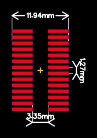
This board has a footprint the Knowles SPU0410LR5H-QB-7 MEMS Analog Microphone.
MEMS microphones are performant and, at 0.76USD/single, cheap. However they are difficult to experiment with unless you already have a PCB with the correct footprint.
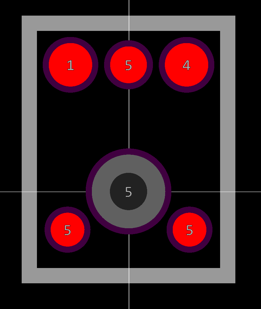
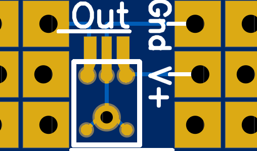
The microphone mounts on this footprint. The V+, Ground and Out terminals are routed to the marked terminal strips.
The microphone port is at the bottom of the package - it listens through a hole in the PCB.
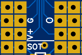
The other side of BlueBoard#01 - shown in the diagram below - has the V+, ground and output terminal strips marked with a “V+”, “G” and “O” respectively. The microphone port comes out next to the “T” in SOT.
Tips on the SPU0410LR5-QB-7
Until you get to know it, this component can be a little finicky to work with.
- All four of the ground pads are connected together inside the package. You don’t actually need to solder them all. It’s better if you do, but you don’t need to.
- The microphone port gums up easily, and then the microphone can’t hear anything. I would advise not soldering this terminal. Be careful to use too much flux.
- The microphone port is a hole in the side of a tiny, delicate machine. I’ve killed a number of microphones with a too liberal an application of Isopropyl alcohol. In normal use, it’s not a problem - just be careful with large quantities of fluid.
- Reflow soldering: Be modest in your application of solder paste, You only need enough to coat each terminal.
Hand soldering: because the pads are underneath the microphone, this component isn't usually hand solderable. However, the BlueBoard#01 footprint features extended V+, Gnd and Output pads shaped to allow a chisel edge soldering iron to heat all 3 pads simultaneously.
- Pre-tin the microphone pads with a little solder
- Pre-tin the whole length of the exposed PCB pads with a little solder
- Position the microphone on the PCB in the outline (double check you have it the right way around, so the the microphone port is over the hole.
- Heat the pads by holding your soldering iron on all three pads simultaneously. This works best with a 2.5mm+ width chisel tip. The solder will melt and flow. Push the microphone down gently with tweezers to ensure all three pads are connected. When all the solder is flowing, you should be able to (very) gently push the microphone to the side and have it snap back into position due to surface tension.
- Remove the soldering iron.
- Flip the board over and check that you can see through hole in the PCB, into the microphone port.
Tips:
- Be prepared to practice until it works. The microphones are cheap - buy a bunch. I have small box containing many dead or suspect microphones, and I'm OK with that.
- You'll likely need a little flux, but keep in mind that it's very easy to use too much and clog the microphone port.
- The microphones are sensitive to heat. A solid, temperature controlled iron set to a reasonable temperature (certainly less than 300°C) and leaded solder will increase your success rate.
Square Pad, Staggered Hole Prototyping
The majority of BlueBoard#01 is given over to square pads. Here are some things to keep in mind when using them.

1. Solder two-terminal surface mount components to the squares.

2. Through hole components can go … through the holes.

3. A row of two or more 0.1” header pins will be held securely by the staggered holes. This is great for adding test leads or programming MCUs.


5. There are three, two-wide bus strips on the board, and also terminal strips running across the board in a pattern familiar to anyone who has used a solderless breadboard. This greatly reduces the need for additional wiring.
