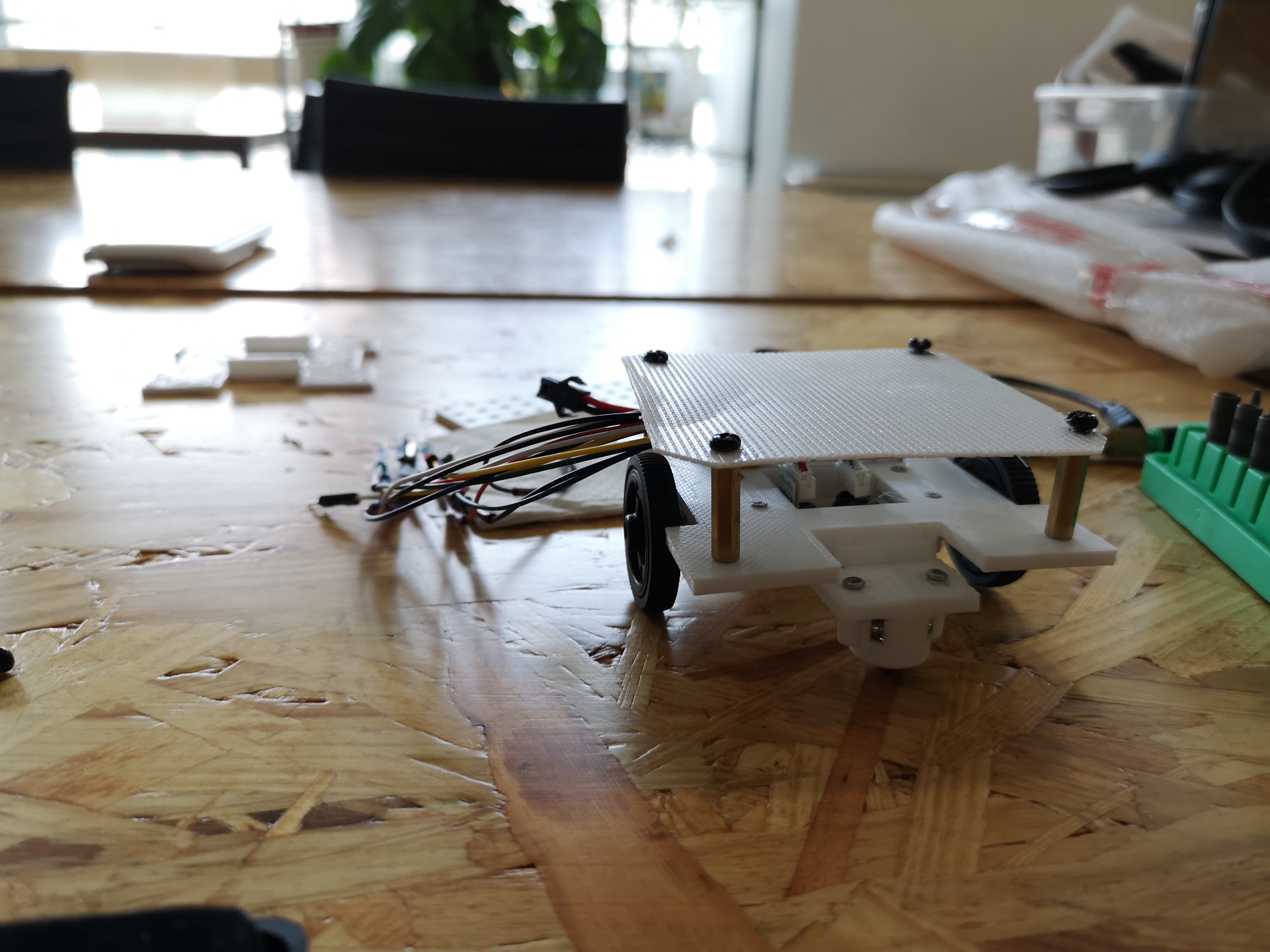
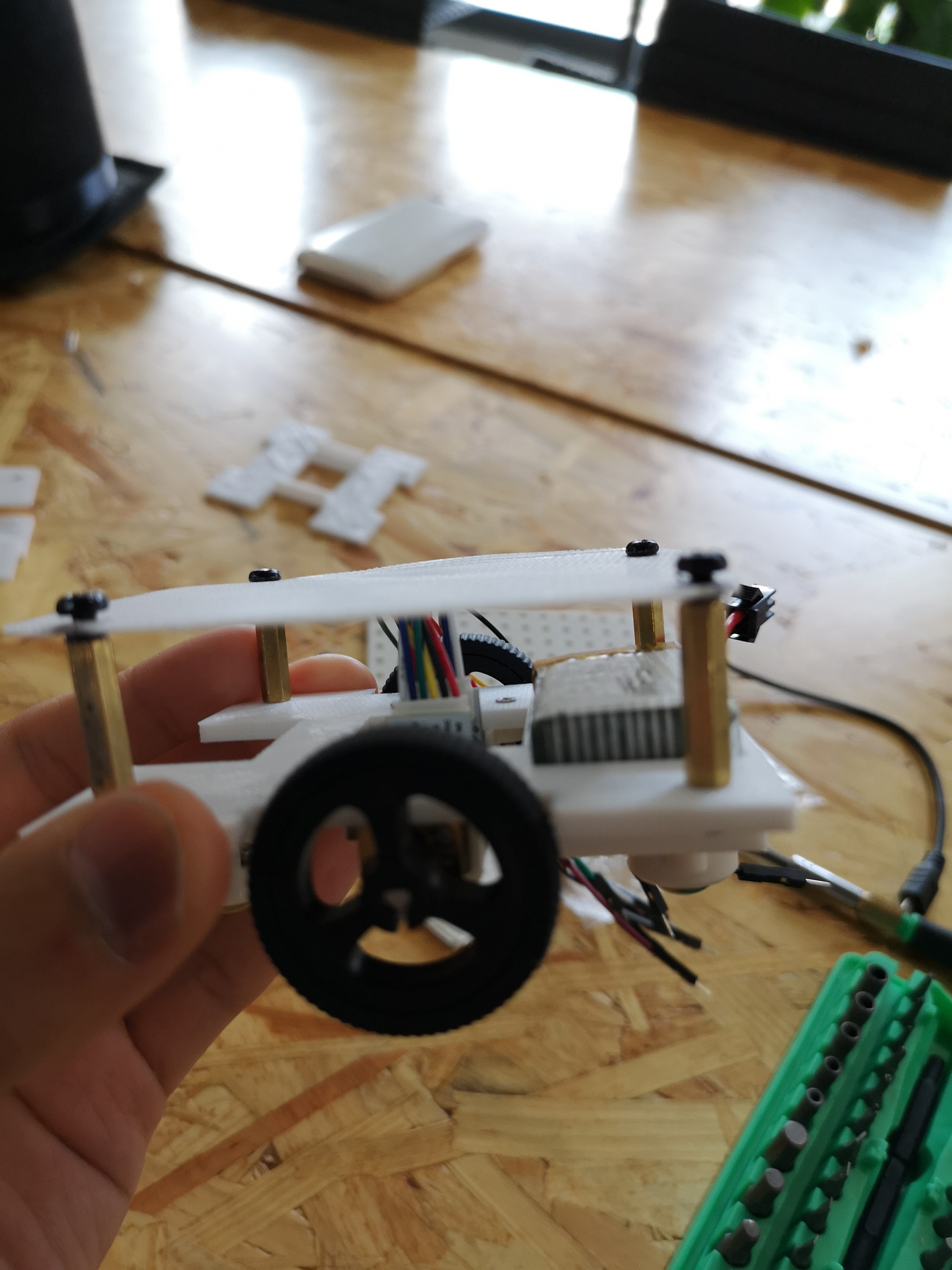
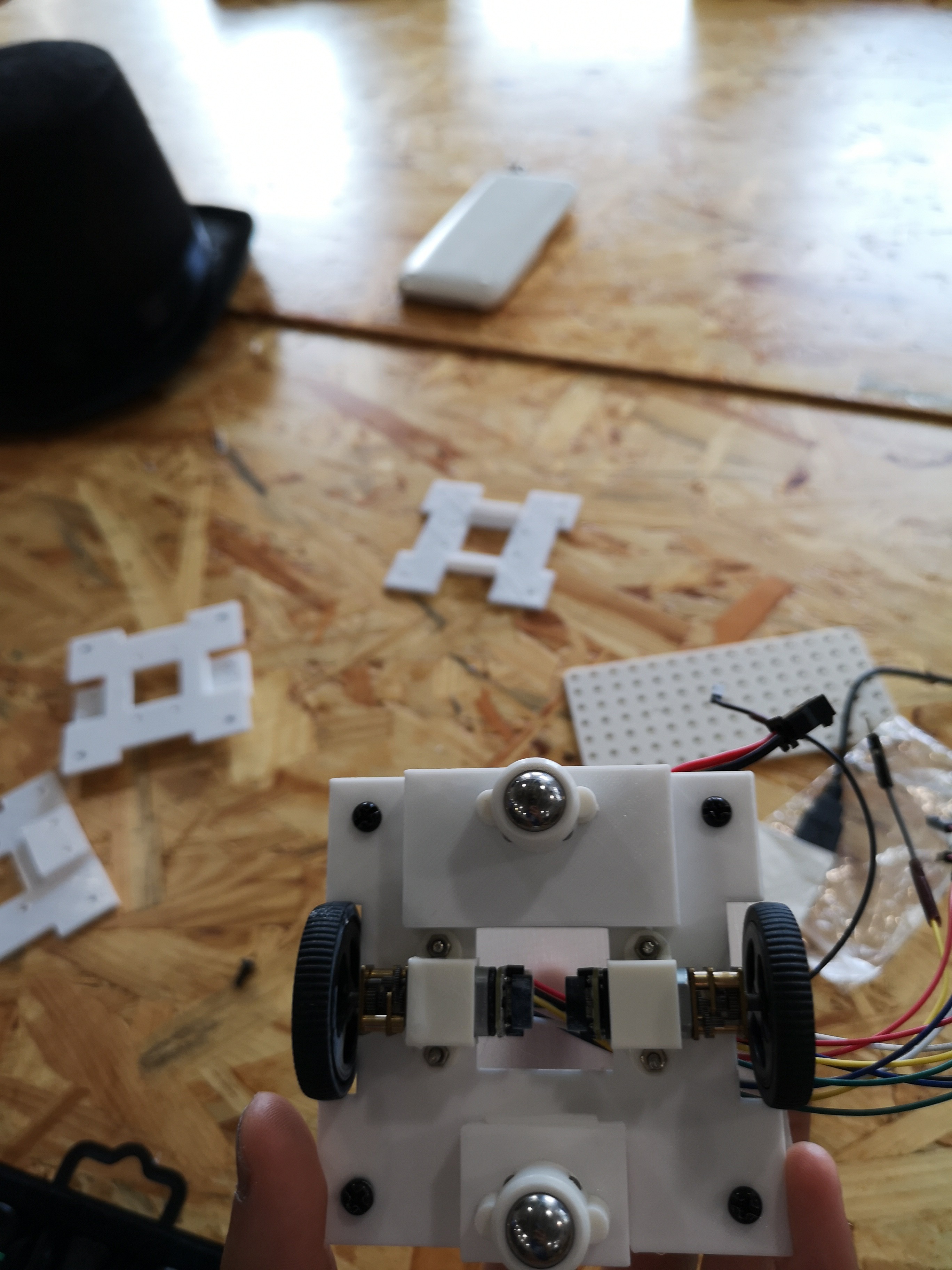
First let us show you how the chassis of our swarm robot looks like:


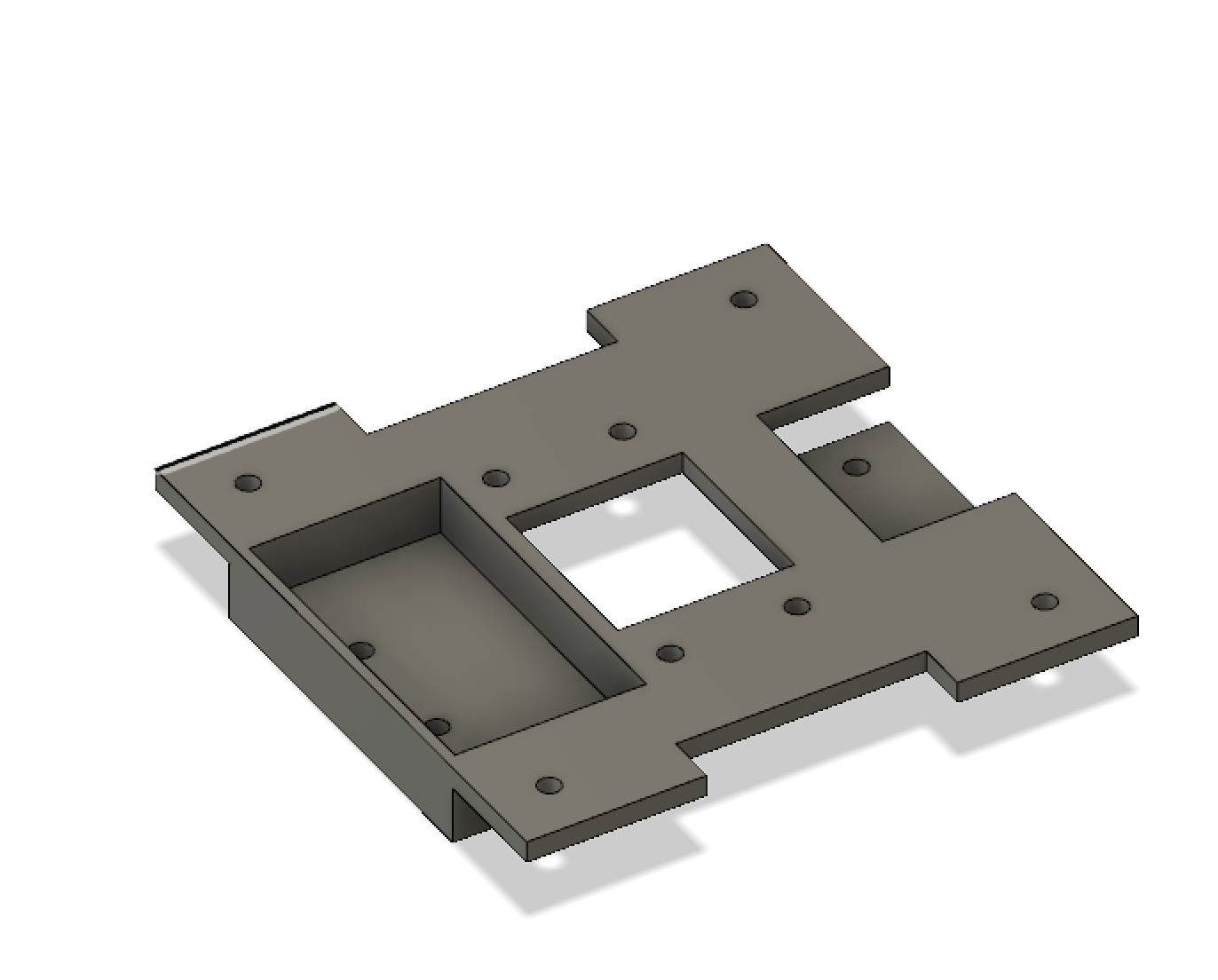
And this is the 3D model of the chassis that we built through Fusion 360
 When we were building the model, we took several things into consideration.
1. The total size of the chassis cannot be over 80*80mm too much
2. Two wheels with motor on it need to be attached on it
3. There should be four holes to attach the chassis with PCB using screws
4. We'd better leave a hole in the middle of the chassis such that the cables attached to the PCB above have place to go
5. The chassis needs to hold the battery
6. Two balls should be attached on the other two sides in order to keep the robot stable.
Taking all the details into consideration and after several modifications to the prototype, we've come up with the first "most-satisfying" version, fitting all these requirements. Further progress of chassis construction will go along with the whole team's process, let us wait and see :-)
 yzh-benny
Discussions
Become a Hackaday.io Member
Create an account to leave a comment. Already have an account? Log In.