Rodolfo
-
Log 7: Annoyingly sensitive IR
06/25/2019 at 15:02 • 0 commentsIntroduction
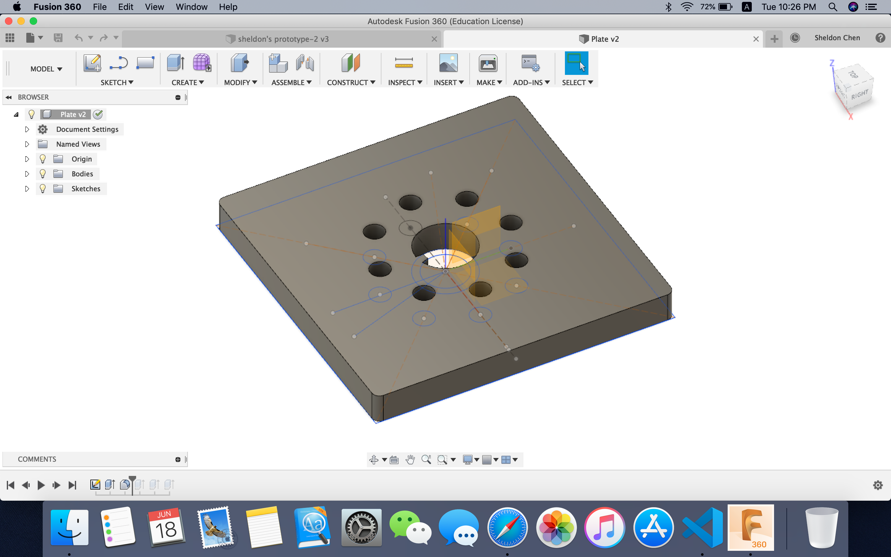
After redesigning the cones and plate using Fusion 360, we also used the chip CD4051BE to read analog input from the receivers while using only one analog input pin on Arduino. The IR system worked pretty well on the Arduino mega 2560. However, numerous obstacles were encountered when switching to the ESP 32 platform.
Obstacles
We first encountered the incorrect readings from the receivers. Similar problem were encountered when using the Arduino platform. Back in the last log (Log 3), we thought it was the result of the uneven surface of the cone. With newly printed, conductive-tape-free cones, however, we start to get incorrect readings from the receivers. For example, ideally, when the emitter is pointing at one receiver, two of its neighboring receivers should get the same, yet lower readings. In our case, however, one of the neighboring IR receivers would have reading 1000mV higher than the other receiver.
For an individual receiver, its highest reading may not occur when the emitter is pointing straight at it, but when it is not aligned.
It could be seen from the video, that the peak value, 2700mV doesn't show up when the emitter is pointing straight at the receiver.
A couple of factors were found by us.
- The orientation of the receiver
After twisting the receiver, we found that only when the connection of both pins overlaps the radius of the circle of the plate, the reading would be even from both sides
2. The tightness of the connection between the pins and the wire.
The readings would be really low when the connection is not tight.
3. Environmental interference
Apart from sunlight, the readings would also be influenced when reflective material occurs in the light path of the infrared.
We were also troubled by the decay in the signal when the emitter moves away. When the range between the receiver and the emitter is above 30cm, the signal is almost negligible.
Implementation
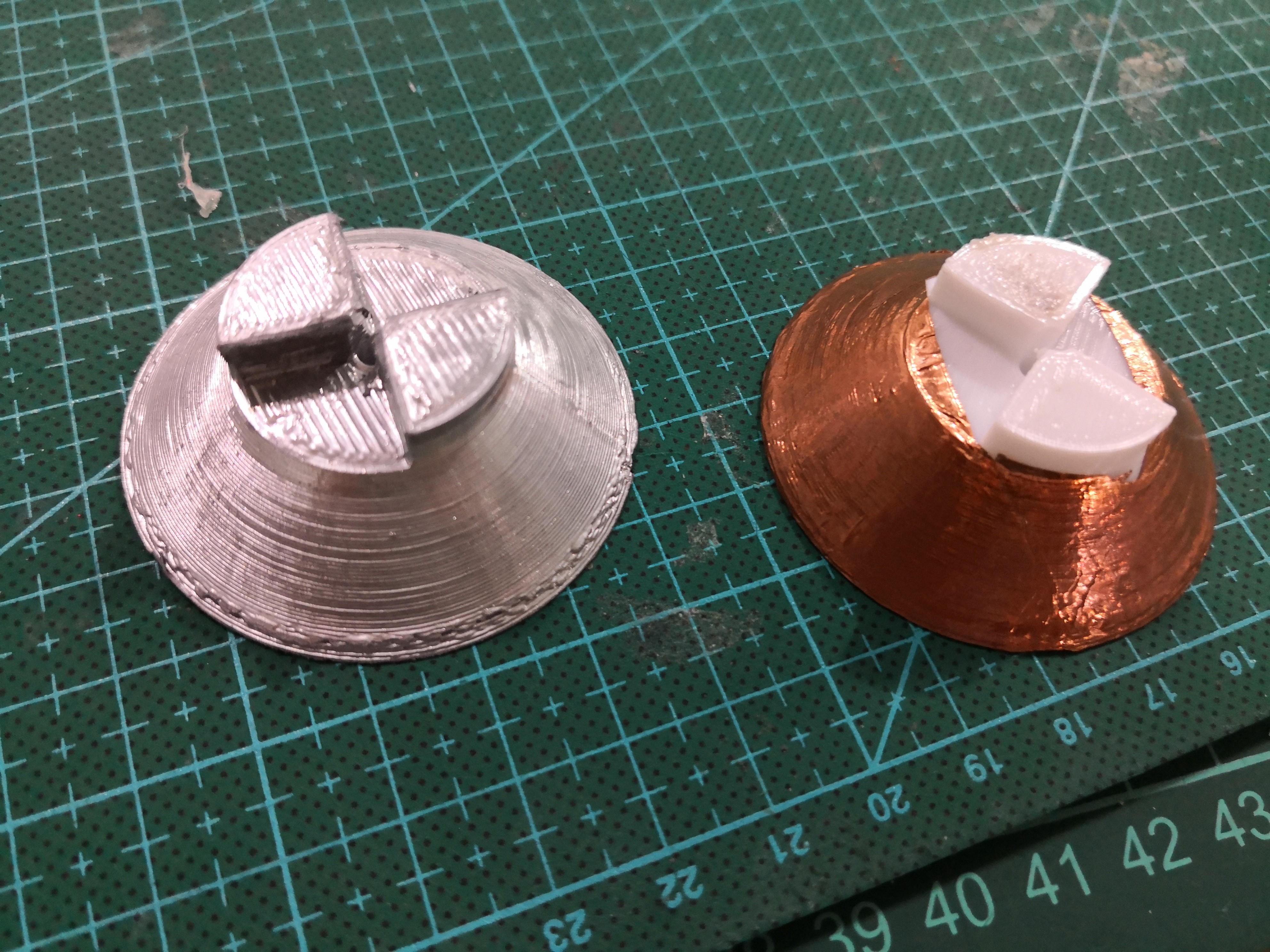
To address the decay in signal strength, we thought of two approaches.
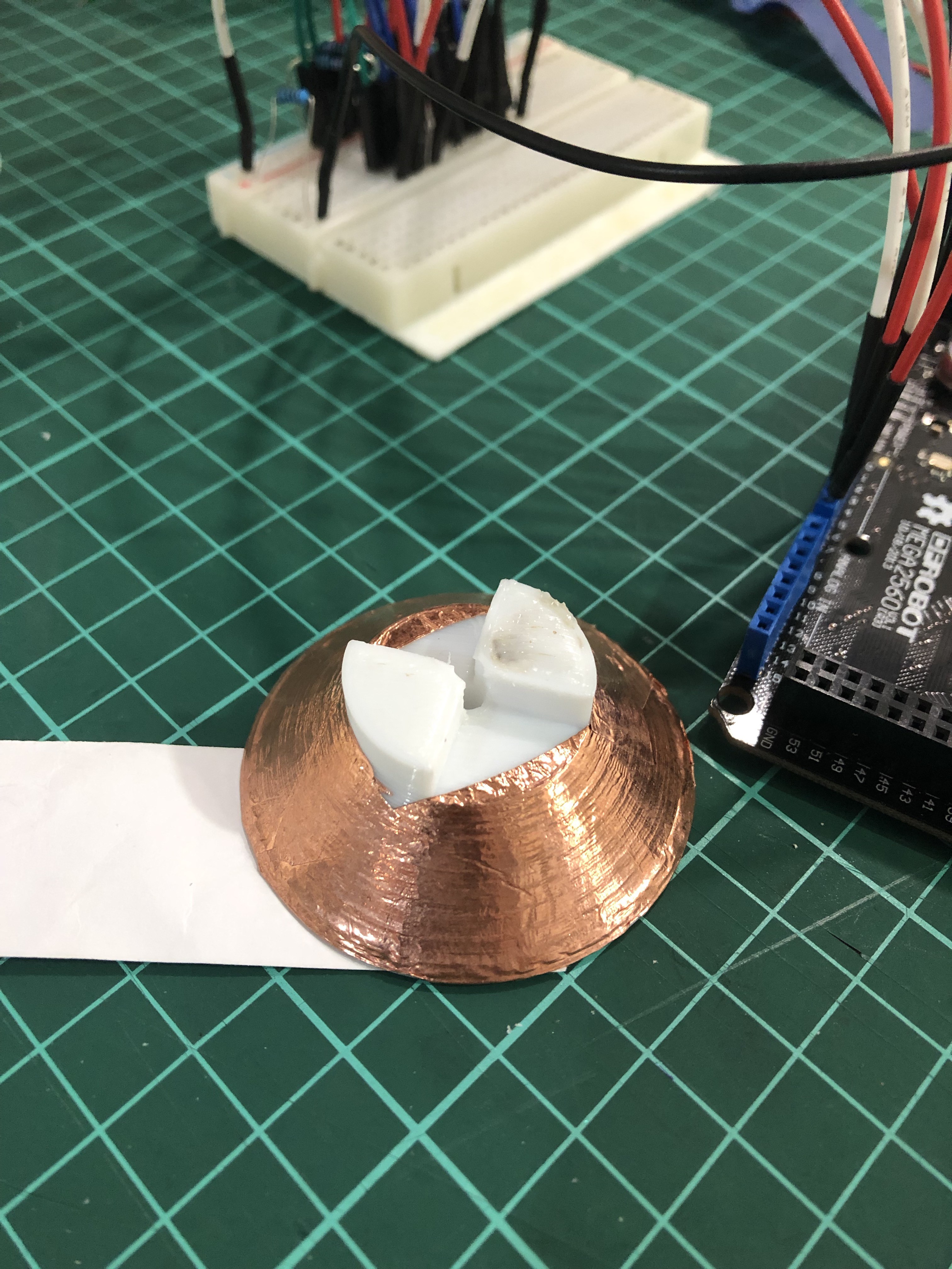
- Apply metal spray on the surface of the cone
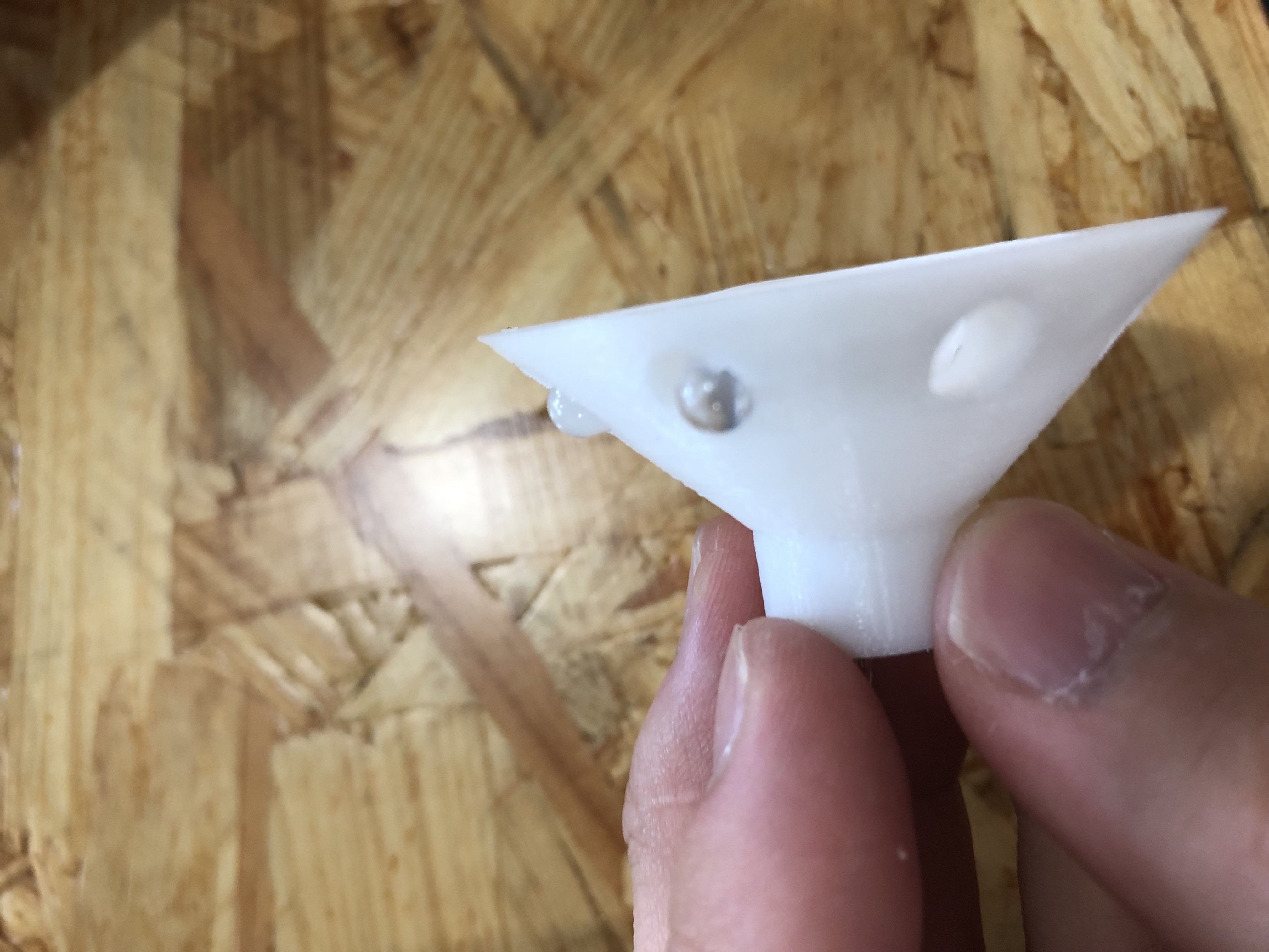
- Let the tip of the IR receivers out of the holes
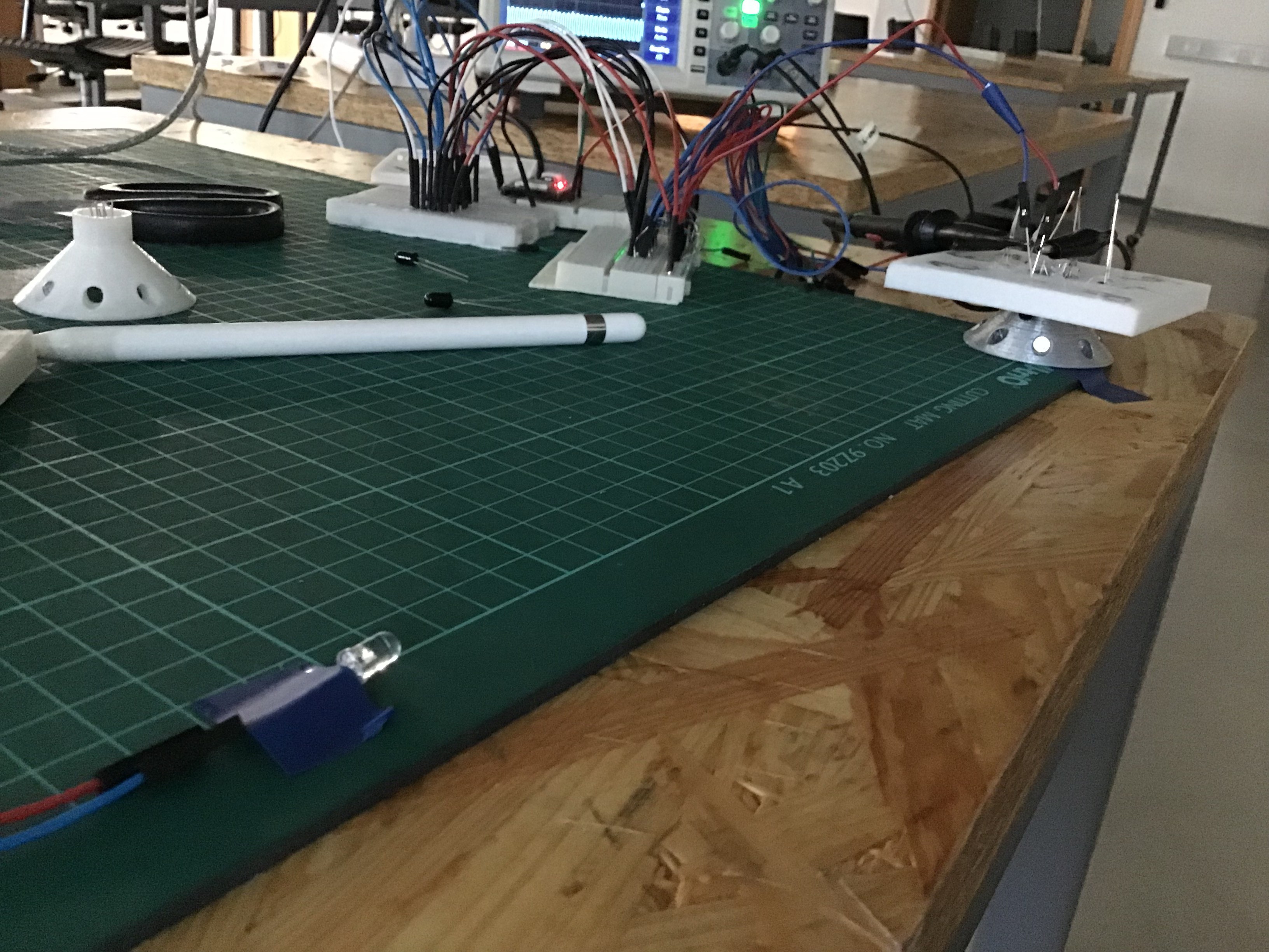
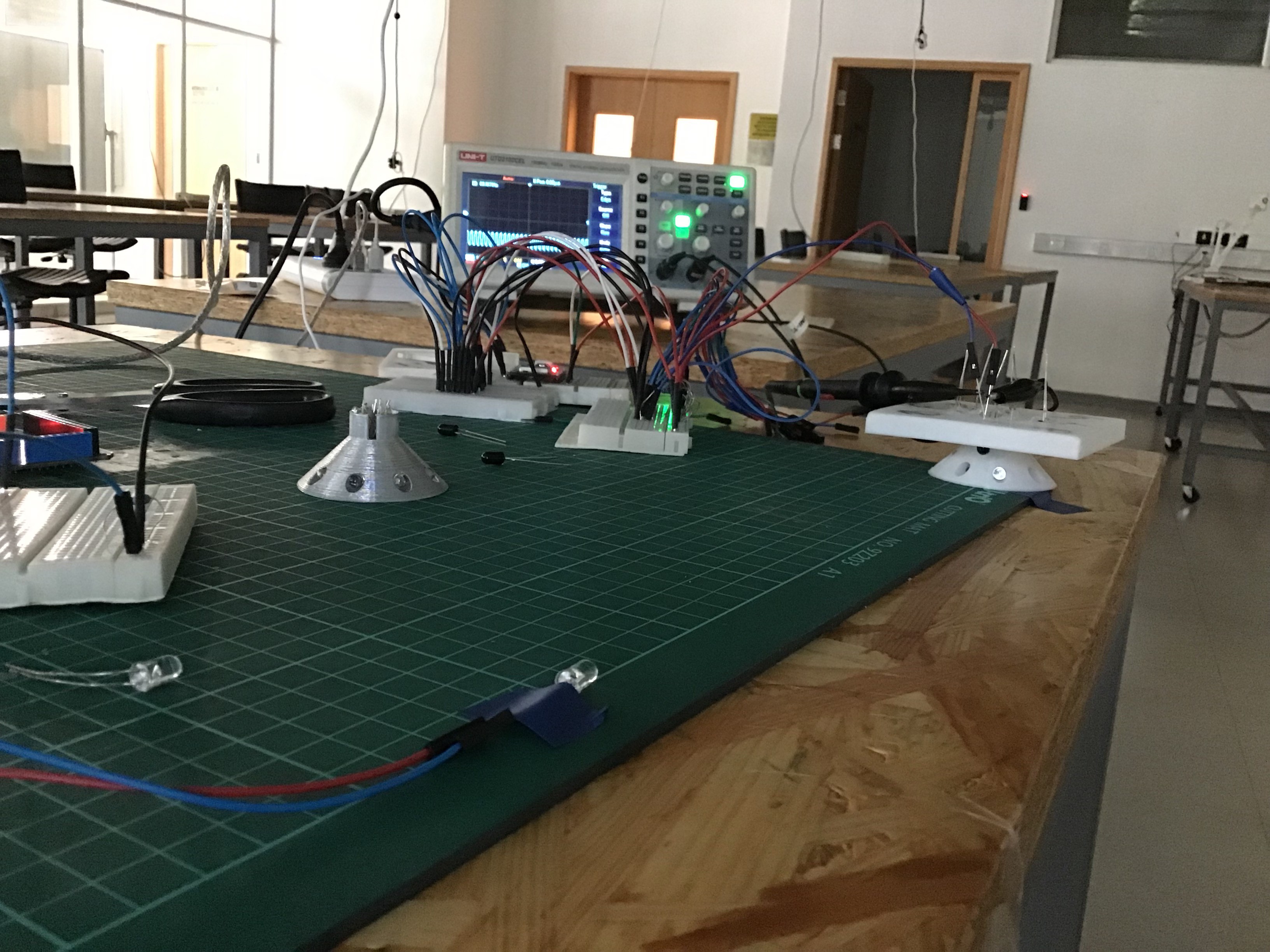
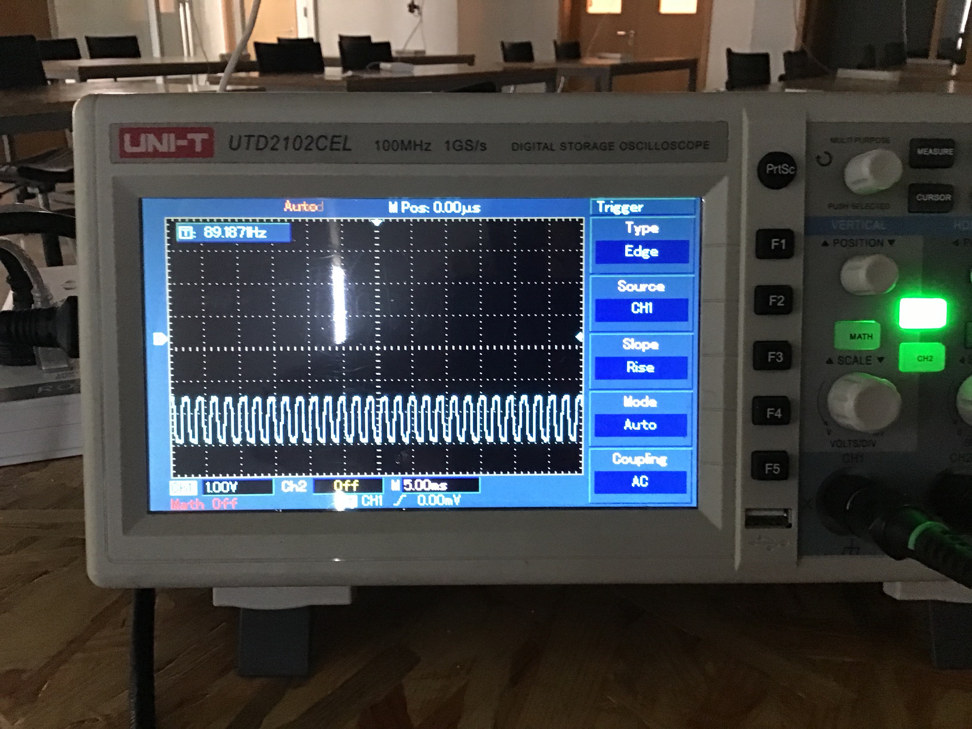
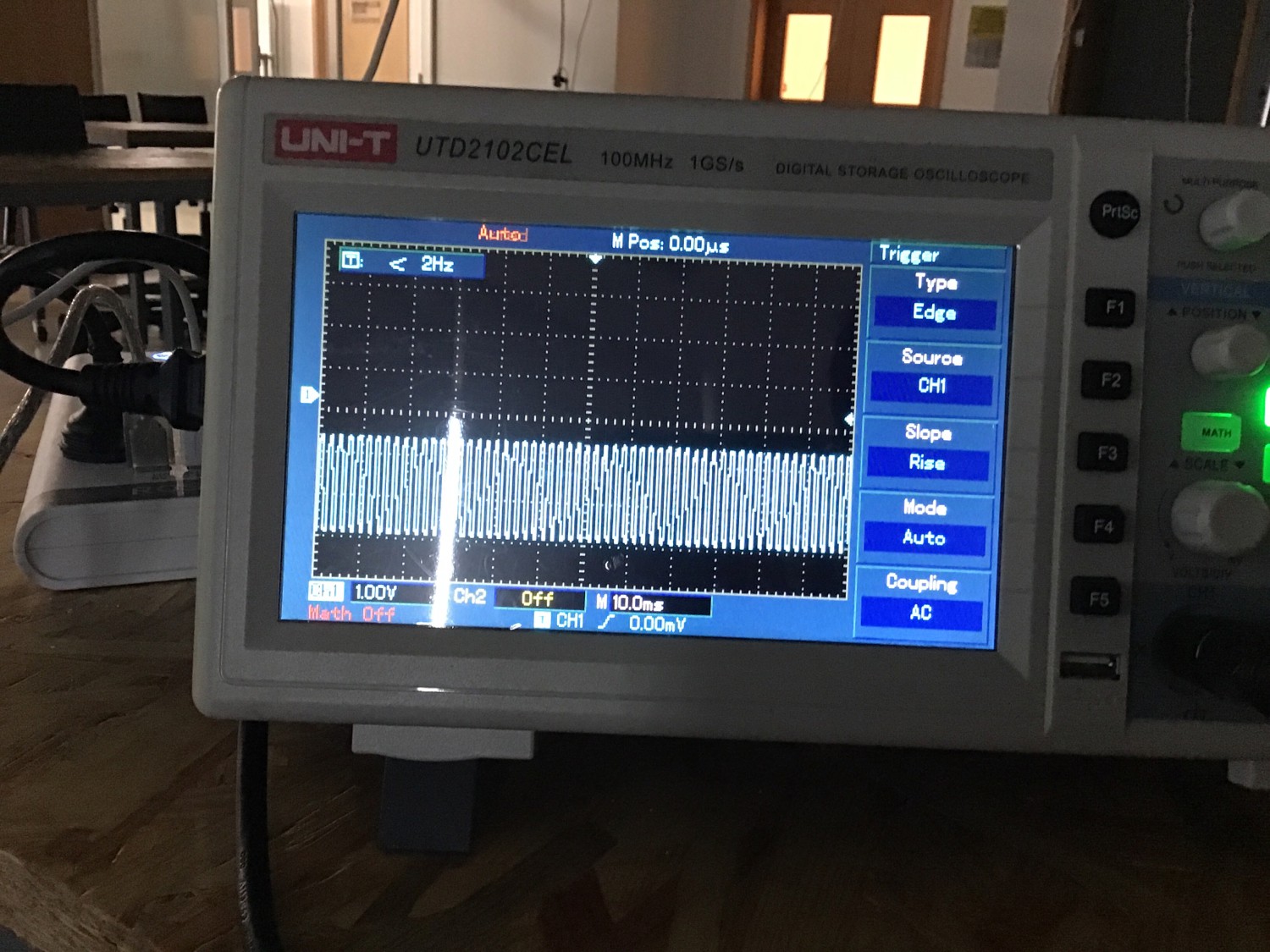
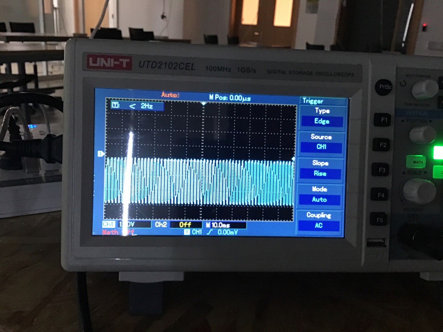
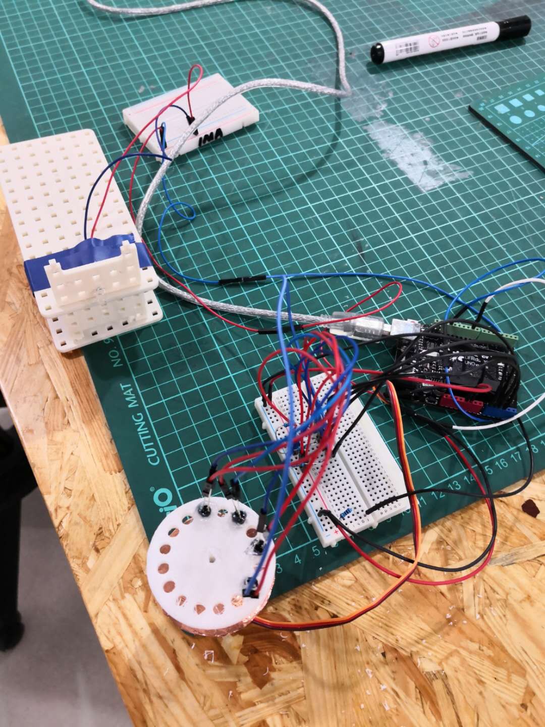
We used the oscilloscope to get accurate results from the receivers.
![]()
![]()
(Cone with spray)
![]()
![]()
(Cone without spray)
![]()
(IR hidden inside)
![]()
(IR exposed outside)
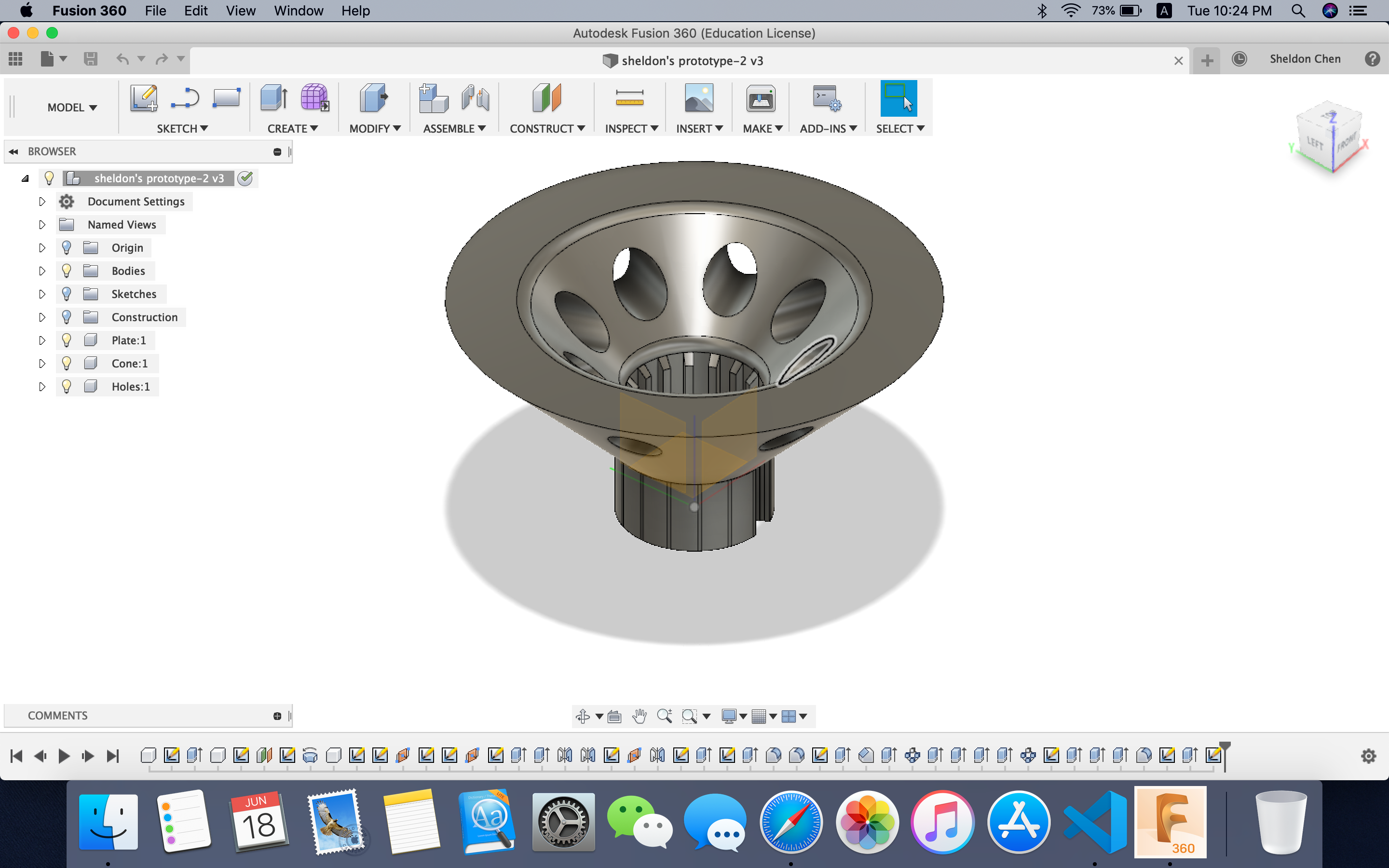
We concluded that the best combination would be exposing the receiver outside and not having spray applied to the cone's surface.
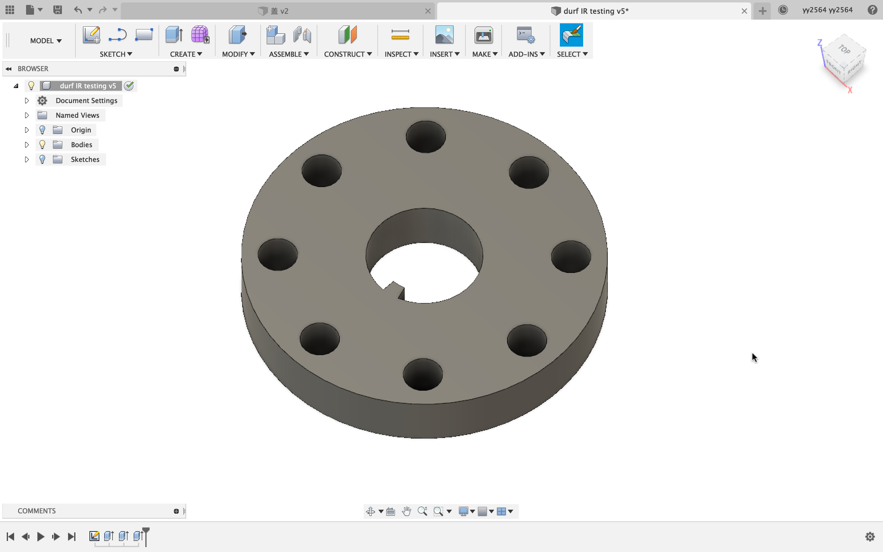
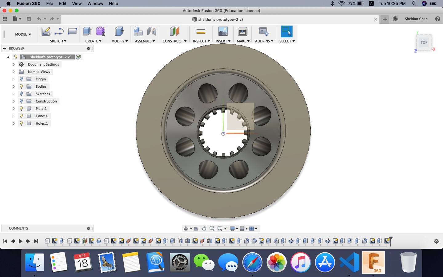
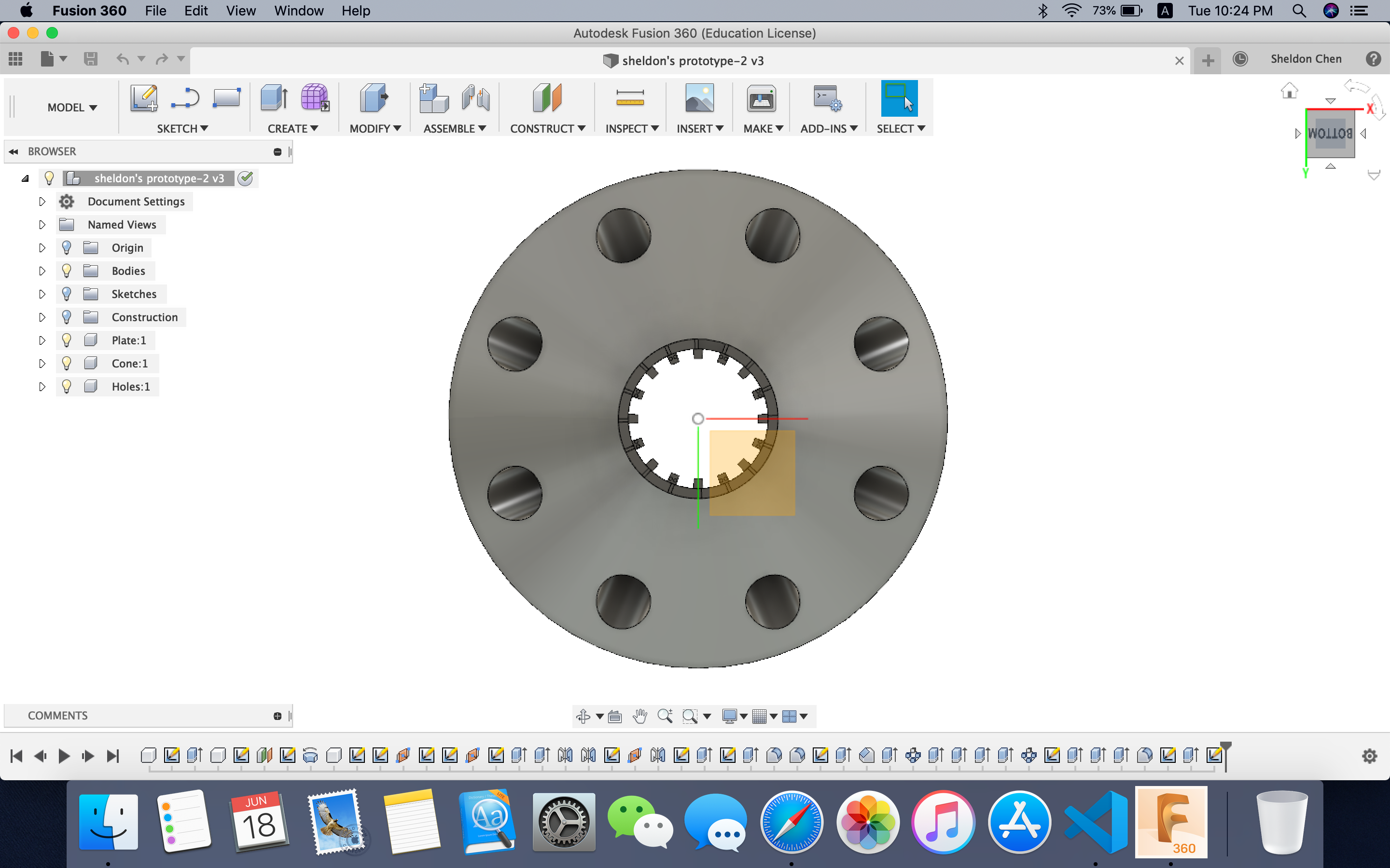
To implement this in our design, we shrunk the height of the cone and the plate by 4mm, so that the receivers would be exposed outside.
![]()
(New design)
![]()
(Original version)
We also tried to let the emitter send infrared signal in a pulse fashion, where the emitter would emit for 1ms and halt for 1ms, waiting for another emission. Though on the oscilloscope, the peak voltage on the receiver is much higher than solely with 3.3V, as we are using the multiplexer to read input from the receiver, it may not be the peak value a receiver receives when the multiplexer is switching to this receiver.
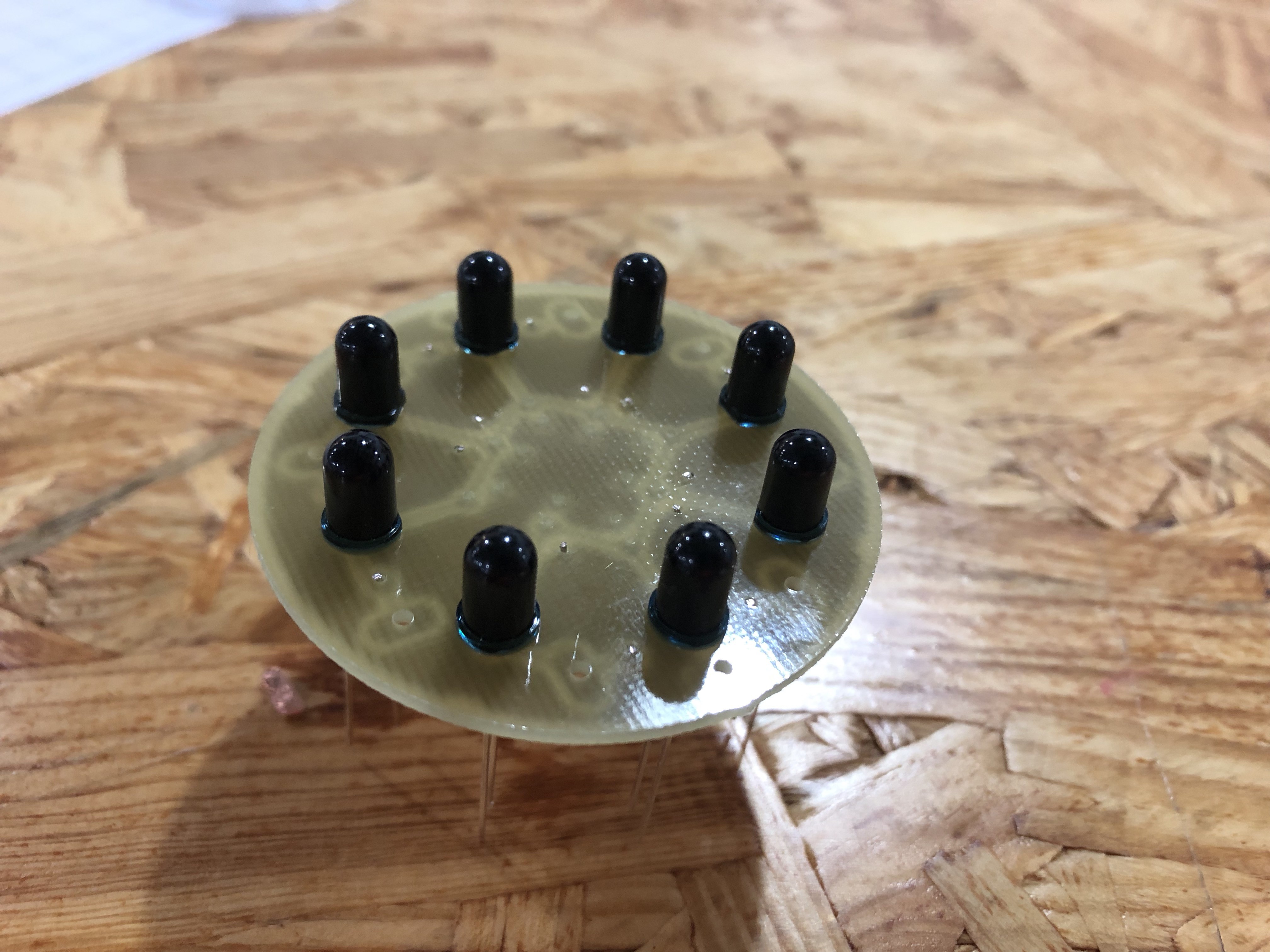
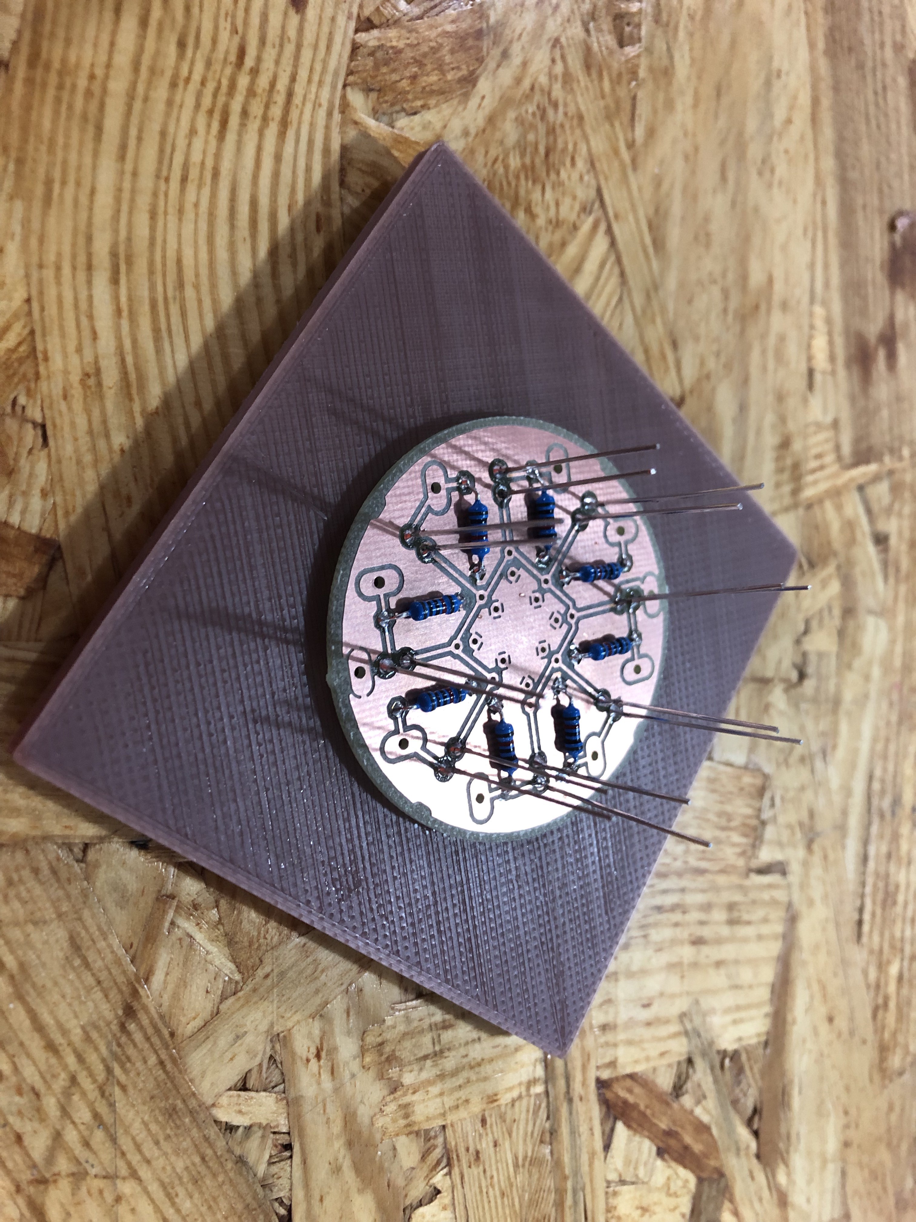
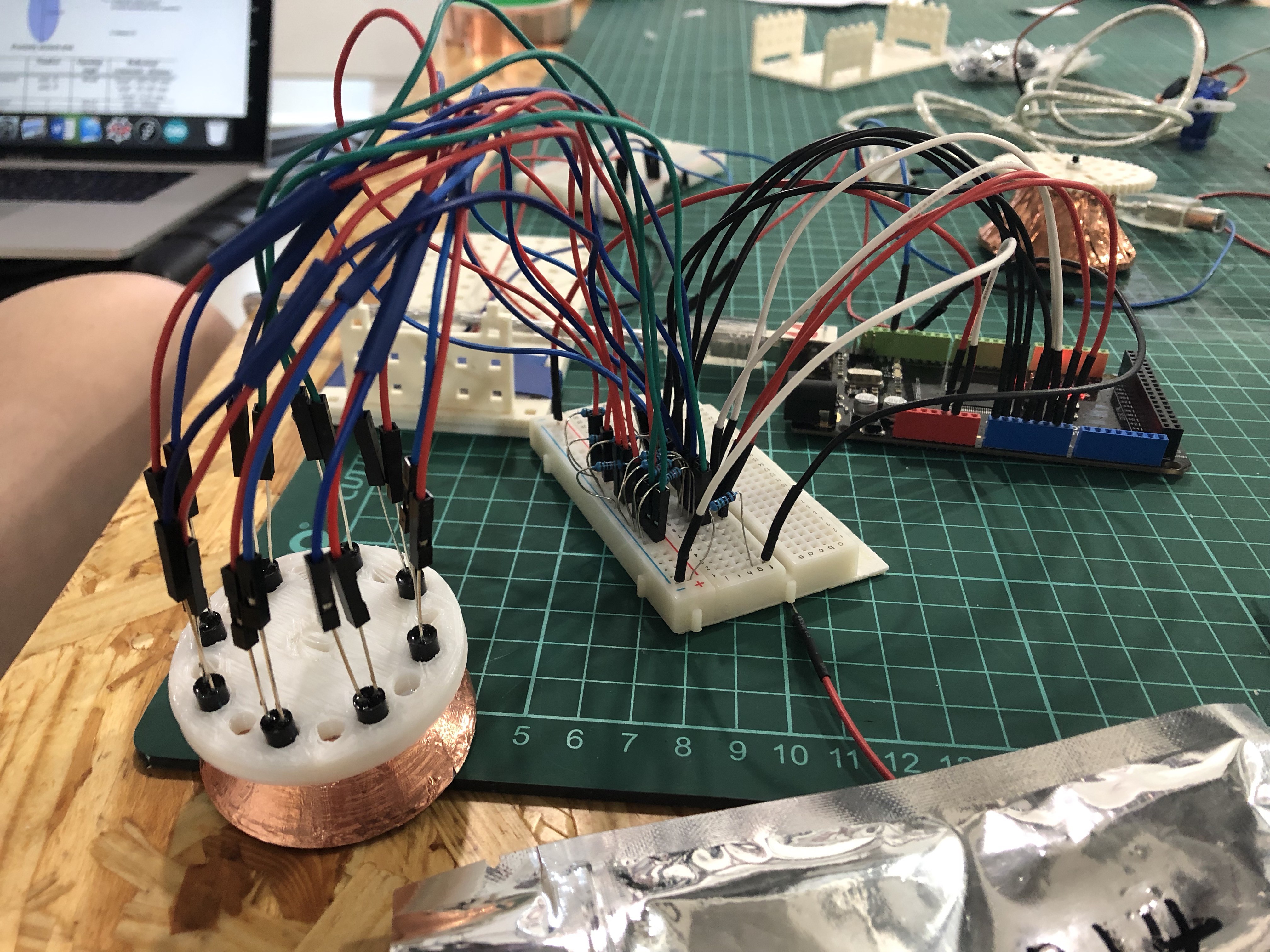
To ensure the connection between the pins and the wire, we designed PCBs and soldered the pins directly to the PCB.
![]()
![]()
-
LOG6: IR Prototype V1.0
06/18/2019 at 16:14 • 0 commentsIntroduction:
This log is an update on the exploration on reflective surface in log 3 and a showcase of the very first prototype (Jun. 11 to Jun. 18). We plan to put the LED Matrix on the top and the IR receivers & emitters right below it. For prototype V1.0, which contains a place for both LED Matrix and IR, we used Fusion 360 to design and 3D printer to print it out.
A Followup on Log 3:
In log 3, we mention testing different reflective surface like using conductive tape. However, the outcome of conductive tape is not very good because it is too reflective and therefore cause more problem with distance sensing. The IR intensity is almost the same for a distance of 5cm and a distance of 10cm at the angle of 0 degree. So, we looked for a less reflective surface and sprayed the surface to add a metal-like texture.
![]()
The picture above shows two reflective surfaces.
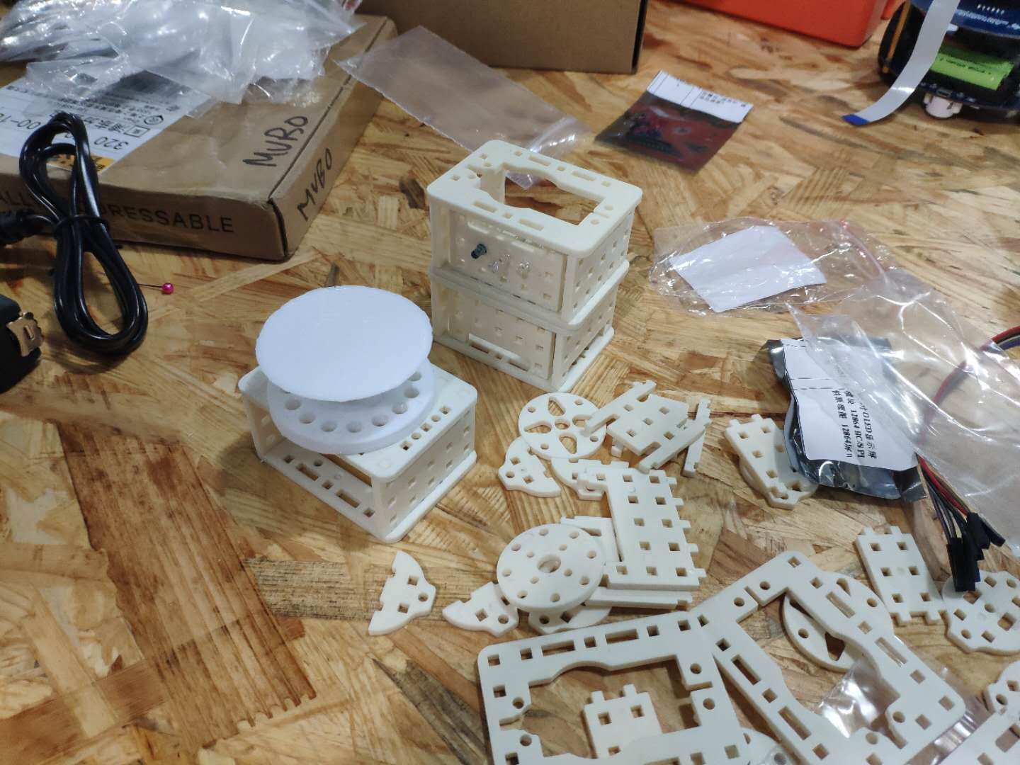
Prototype:
Design:
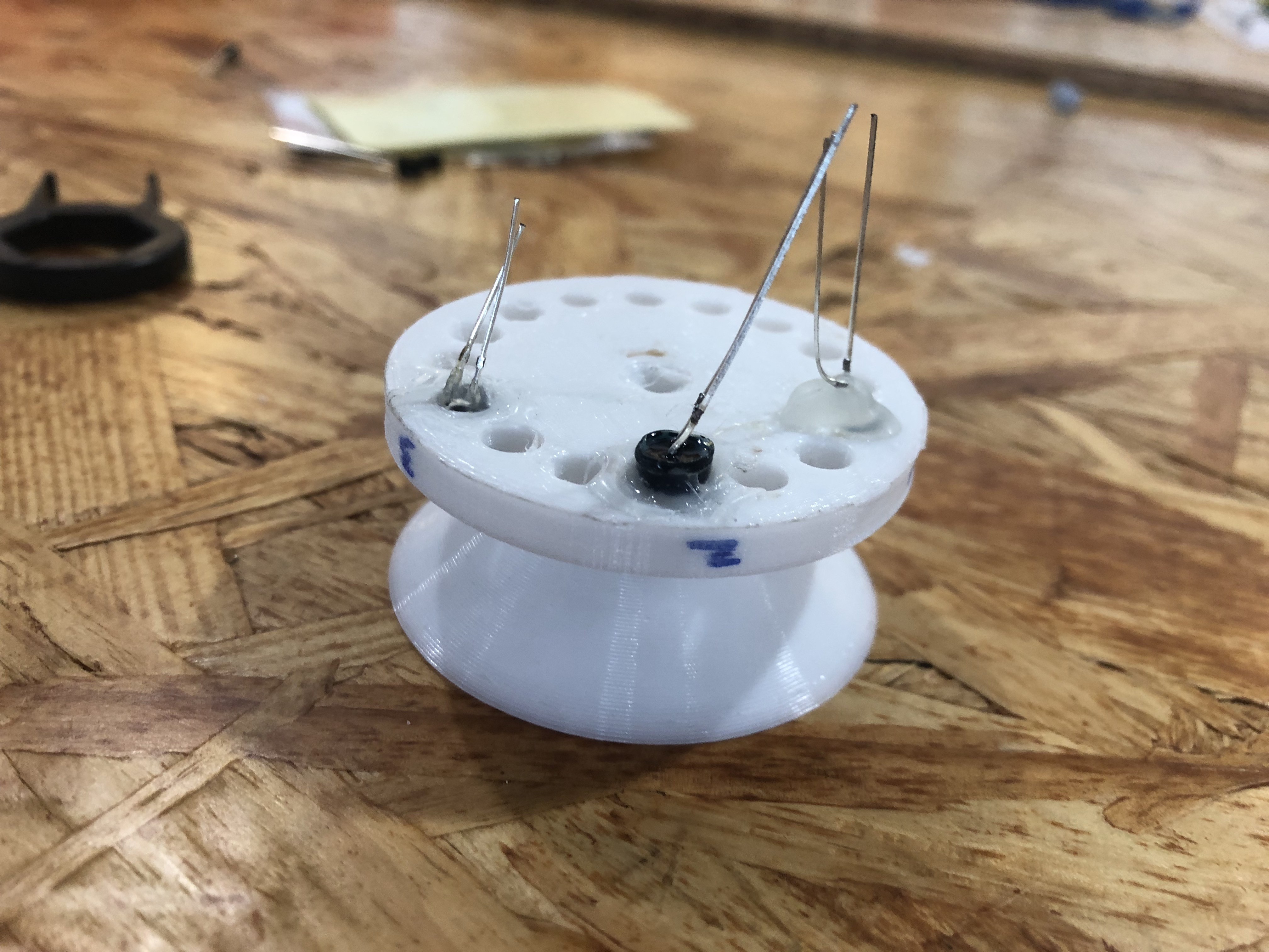
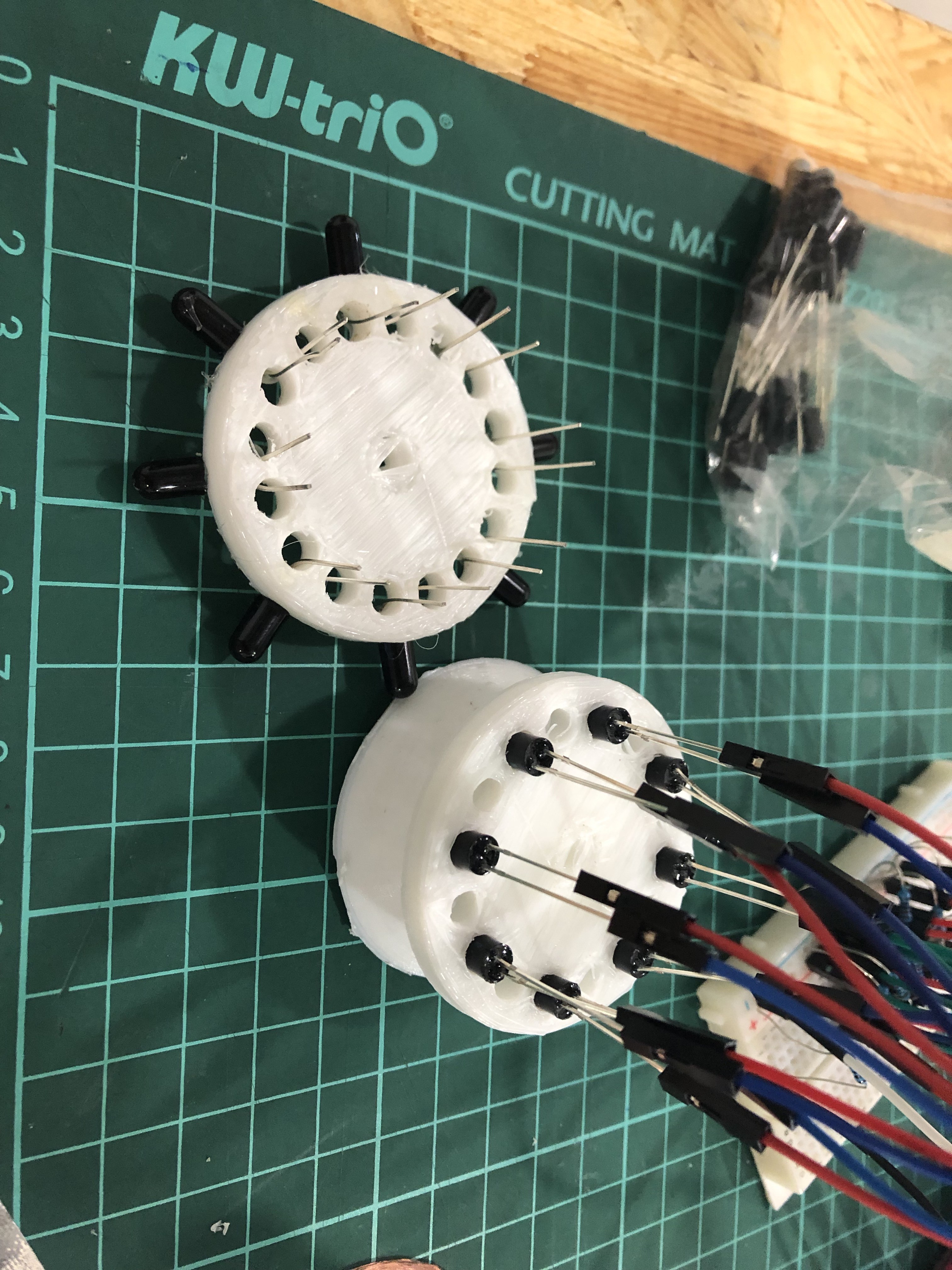
We used Fusion 360 to draw the 3D sketch of the prototype, which consists of three parts. All three parts need to able to be fixed onto one another without using hot glue. Here, we present the three parts from the bottom up.
The first part is the IR receiver holder. There are eight holes for eight senders in the shape of a circle. The diameter is currently 50mm. However, the distance between the center of each hole to the center of the big circle is kind of random. We are still trying to find the best distance.
![]()
The second part is the IR emitter holder. Its shape is made according to the first part. So are the position of the holes. The big hole in the center is for the legs of the emitters. And the legs are separated based on the design.
![]()
![]()
![]()
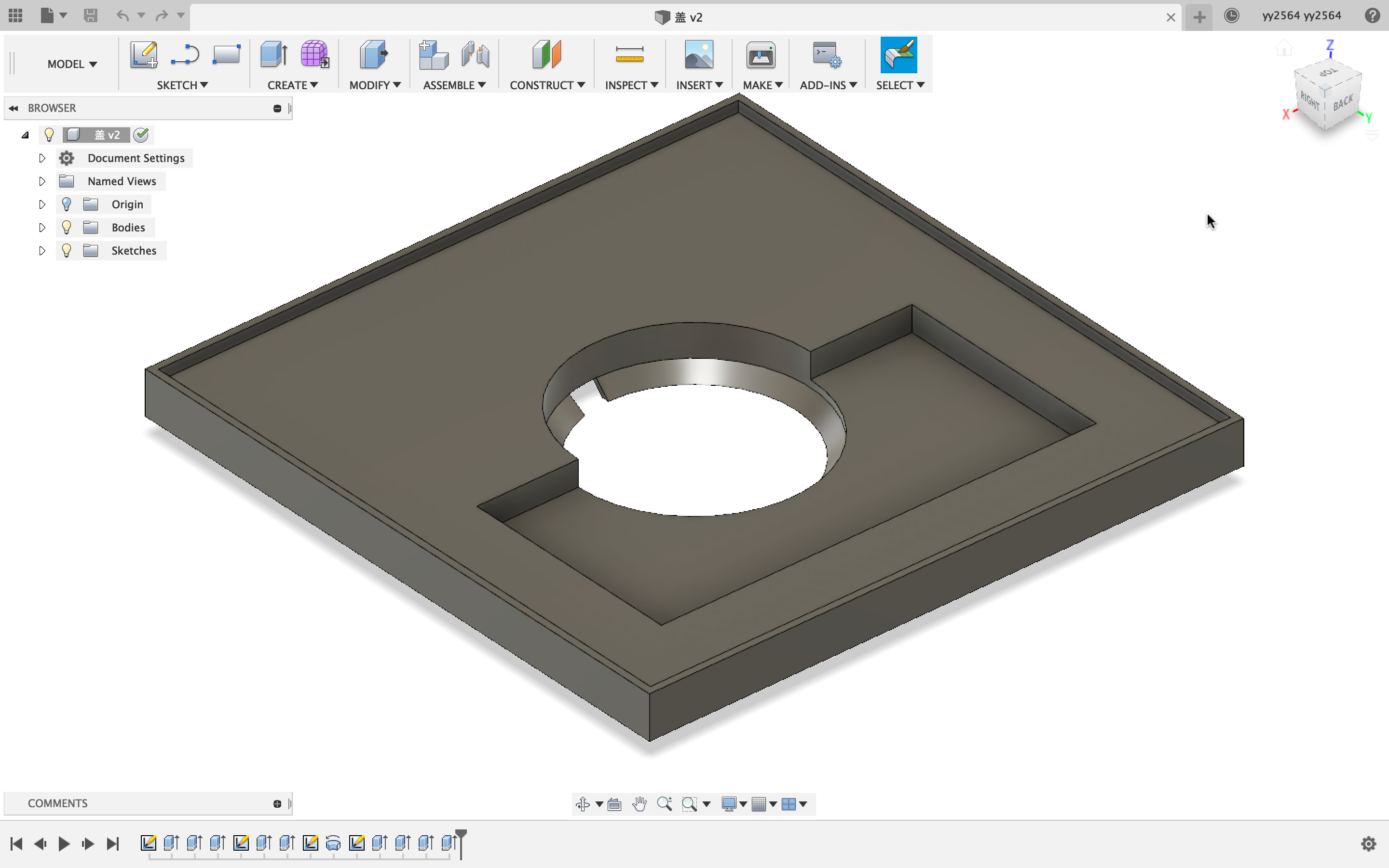
The third one if the LED Matrix board. It should be able to fit the LED Matrix perfectly and leave a hole in the middle for the wires to go through. Also, there need to be a slot for the wires on the board.
![]()
Implementation:
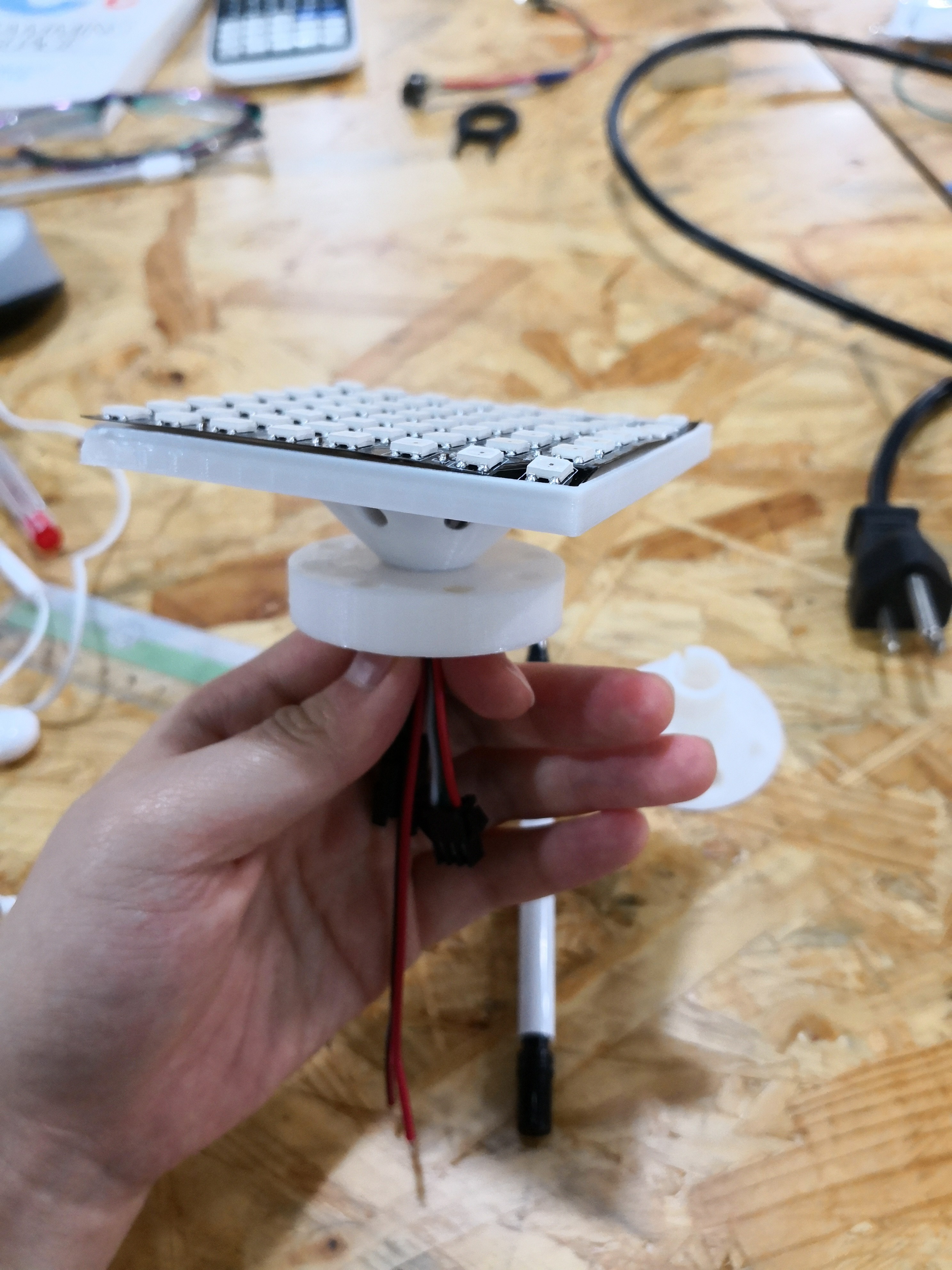
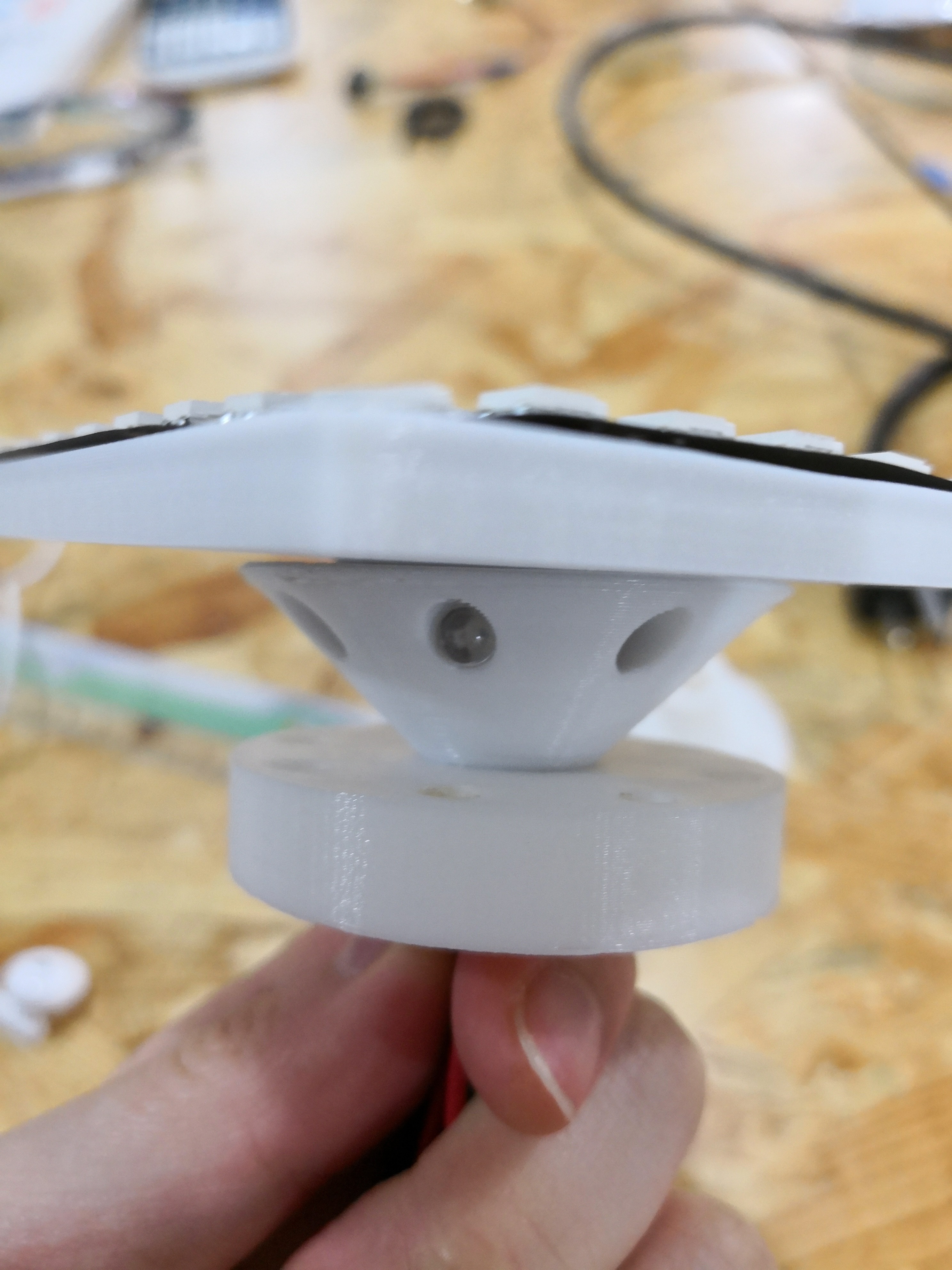
We printed all three parts out and assembled them.
![]()
![]()
The prototype is good in many ways and we expect that there wouldn't be much big changes.
Further Improvement:
1. To fit the size of the robot, which is 8cm*8cm, we might expend the first part as below.
![]()
2. The distance between the center of the receiver and the central hole needs further exploration and more tests to find.
3. We need to redesign the way the second and the third part fit together. We expect to use two poles sticking out on the board and two holes on the IR emitter holder.
-
LOG5:POWER MONITORING(ADC)
06/17/2019 at 10:13 • 0 commentsIntroduction:
We think it would be great if our robot can tell us when we need to recharge it. To do that we used one of the ADC pins for testing. The result is pretty good.
Design:
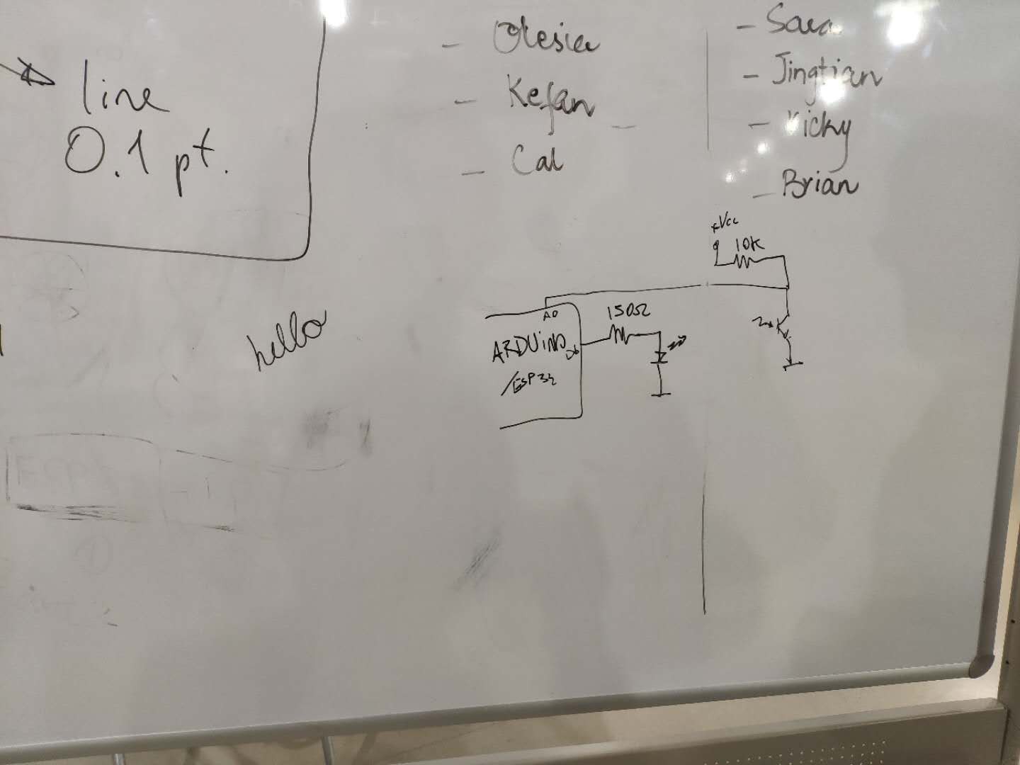
![]()
We are using a 7.4V Li-Po battery for the robot. ESP32's ADC pins have several modes, which have different voltage input ranges. We are expecting a 12V peak when charging the robot, so the circuit is designed to be able to handle 12V input and the maximum voltage for the ADC pin will be 2.4V. The 0.1uF capacitor is for wave filtering.
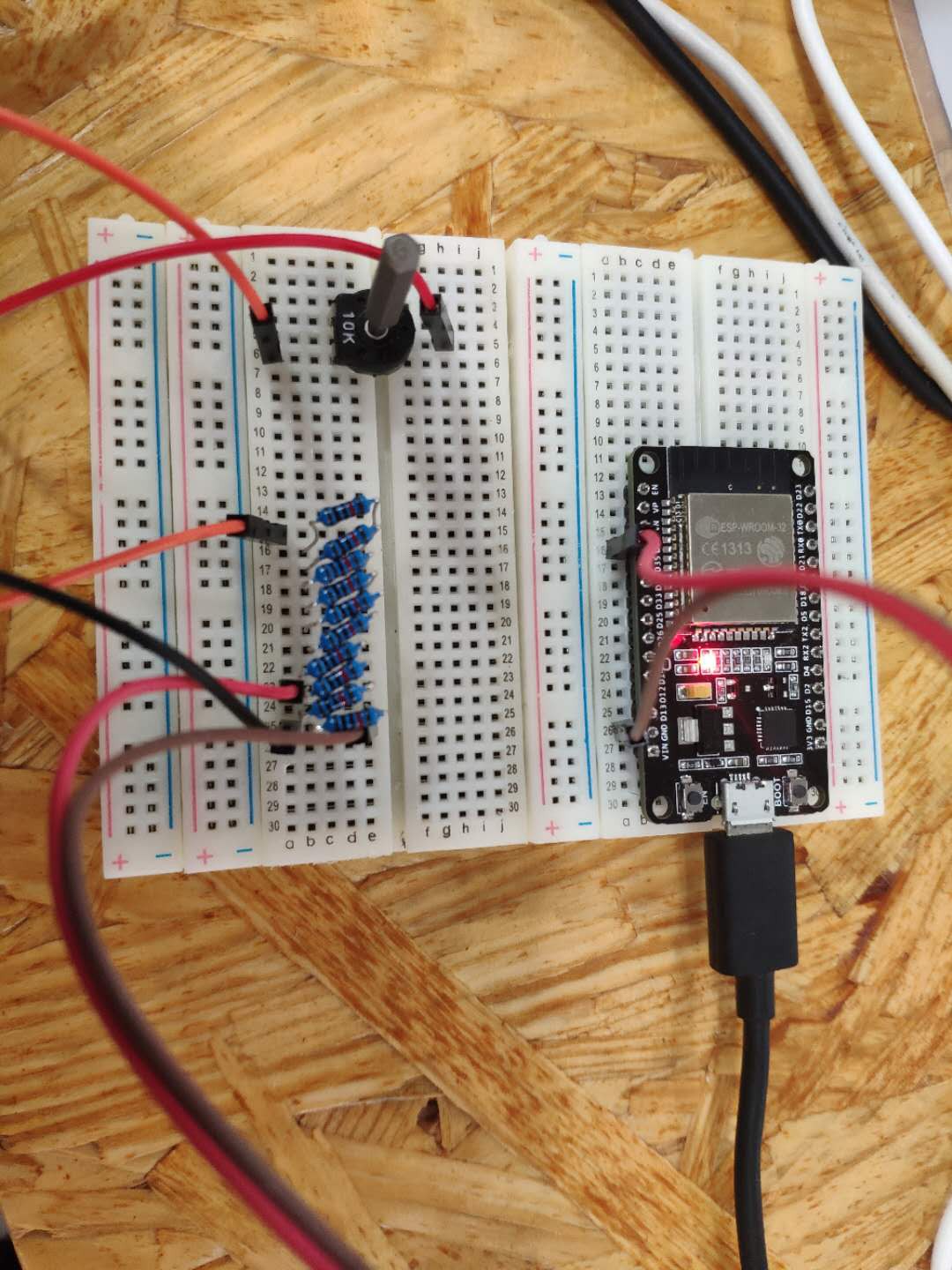
Experiment& Result
We are using a 10k potentialmeter to simulate the case where the voltage of the battery drops. We don't have 80k/20k resistors for the moment, so we used 10*10k resistors for the test. The result was pretty good. Also, since the voltage drop is not entirely proportional to the battery level, we would just set a threshold value for low battery, and some signal to indicate that it's power is low. Result is shown in the video below.
-
Log4:UART+ESP-MESH
06/15/2019 at 03:19 • 0 commentsIntroduction:
This log is based on the experiments on ESP-MESH with UART from June 11 to June 15 using esp32. Since other devices cannot directly communicate with the nodes in the mesh, It will be very easy for us to manage the swarm if we can directly control one esp32 with UART and use it to join the group.
Method:
The test is based on two example project of esp-idf: peripherals/uart/uart_echo & mesh/interal_communication. We use a Producer/Consumer model to link them together.
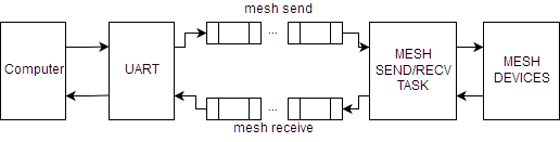
For the station, The idea is to establish two message queues, one for mesh send and another for mesh receive. Every time an esp32 receives a message from UART, it will put it in the mesh send queue. Another task will listen to the queue, once there is an item in the queue, the mesh send task will dequeue it and send it to the mesh network. Vice versa, once the station receives a message from the mesh network, it will send the message to the uart receive queue. Once the UART receive task detects that there's an item in the mesh receive queue, it will send it back to computer through UART. Thus we have an asynchronous duplex communication with the mesh network.
![]()
For the robot, right now it just receive the message and respond to the station.Coding Detail:
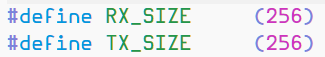
The data pack size sent through the mesh network is defined at the beginning of the code:
If the size of the data is too big, the latency will be high.
For the task to listen to the queue forever, the third parameter in the xQueueReceive() function should be set to portMAX_DEALY. If set to 0, it'll return immediately if the queue is empty.
Test code can be found here:
Mesh Station:
https://github.com/Zander-M/NYUSH_DURF_2019_SWARM_ROBOTS/tree/master/Project/Code/MESH_STATION
Mesh Robot:
https://github.com/Zander-M/NYUSH_DURF_2019_SWARM_ROBOTS/tree/master/Project/Code/MESH_ROBOT
-
Designing V1.0
06/11/2019 at 04:51 • 0 commentsAfter seeing that the chassis that we were initially using was not extremely customizable (as well as hard to dissemble and reassemble), we raided our robotics room to see if there were any alternatives. Fortunately, we have boxes and boxes of grid like plastic parts which we can assemble almost like legos. With this, we had a very simple structure for now that is easy to assemble, attach things onto, and have enough space for more. We will get back to this design later, especially since the front wheel placement is messing up sometimes the direction the robot goes using its back motors.
![]()
For now, we are also trying to find a way to position the robot based on its angle and turn correctly.
-
Log 3: Progress and Barriers in IR Positioning
06/11/2019 at 03:16 • 0 commentsIntroduction
The ability of perceiving surrounding environment, especially other robots among individual robots is the key for the swarm group to take action collectively.
Just as many other swarm robotics program, we have attempted using the IR to accomplish the task. Ideally, one emitter on one robots would send infrared signal constantly, and another robots would receive the infrared signal from other robots and determine the distance between them based on the intensity of the infrared signal.
Implementation
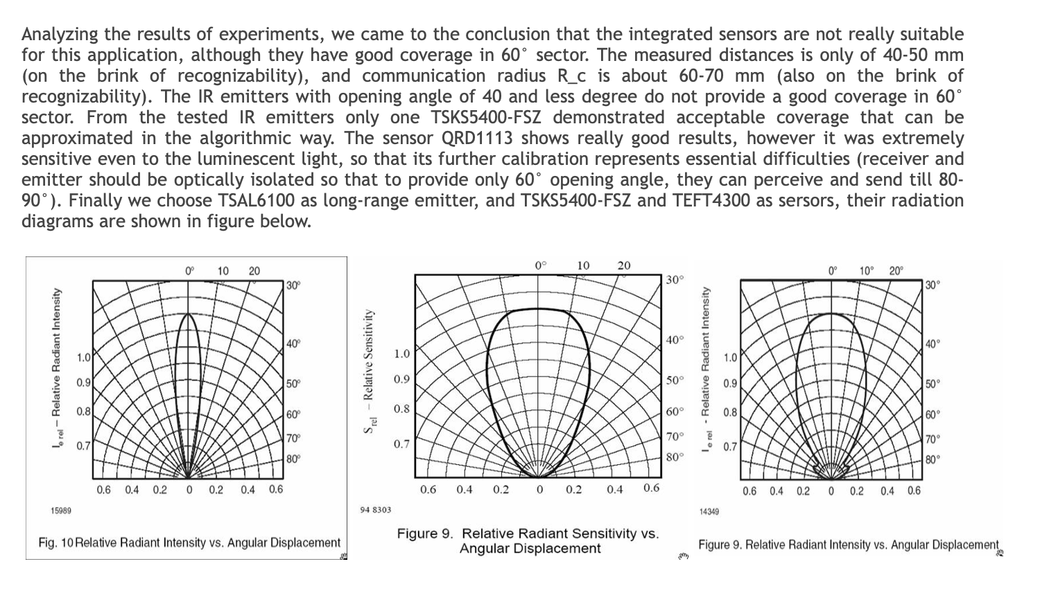
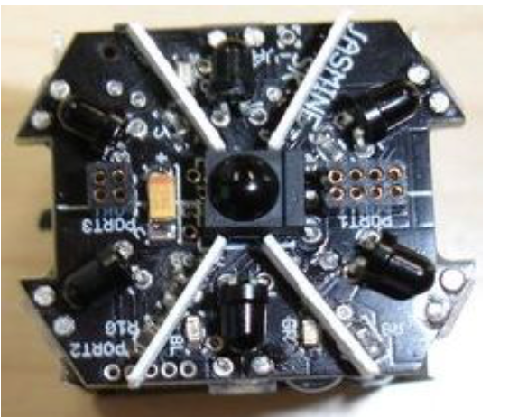
However, as the Jasmine team has discovered, with relatively low density of IR receivers, the intensity of infrared signal another robot receive would become a petal.
![]()
In other words, with infrared signal shooting at the middle of two receivers or directly at one receiver from the same distance, the intensity would differentiate, where the one shooting at the middle of two receivers would decrease dramatically.
To better address this issue, we thought of using a cone, where diffuse reflection would occur at its surface, through which even the infrared is shooting at the middle of two receivers, the light would also reflect and enable the receivers to receive equal value of infrared.
![]()
To better reflect the test result, we combined Arduino and Processing, where the Arduino would read the intensity of infrared using analog input and send the values to Processing. The Processing would in turn draw an infrared intensity map based on the value sent from the Arduino, while saving all the data in a text file.
![]()
As shown in the video below, in the pilot test, we only used four receivers. The result of the test, however, doesn't seem satisfying. Though the blind spot between two receivers has shrunk thanks to the design, the reduction in IR intensity still exists.
Initially, we thought it is resulted from the surface of the cone being not smooth and reflective enough. So we put conductive tape, assuming that it would improve the readings.
We also increased the density of IR receivers by decreasing the included angle between two neighboring receivers to 45 degrees.
Though the range of detecting infrared signal has greatly increased, the peak value among different IR receivers vary, which might be the result of not even surface of the tape. After taping the cone evenly, the situation has improved.
![]()
This also led to another problem. Within the range of 5 - 25cm, there would only be minor decrease in the infrared intensity as the emitter moves away from the receiver, which might undermine the precision in positioning.
![]()
When we were about to be defeated by the results, we put 8 receivers and tested it.
The result turned out to be very promising, as when the infrared red signal shoots right at the middle of two receivers, the value of intensity won't change so dramatically.
![]()
What's even more exciting is after removing the conductive tape, the feature mentioned above would persist, the capacity of estimating the distance based on the range would greatly improve.
Backup Plan
Our backup plan, the Sunflower plan, is to use the same type of design in Jasmine.
![]()
![]()
(The one on the left)
The final data, as we expected, shows a very obvious blind spot between two neighboring receivers.
-
Ground Zero
05/13/2019 at 06:13 • 0 commentsThe very first conversation about this project happened at my office back in 2018. A couple of students reached out to me asking if I could support a robotics club. We had since then have been working on different concepts, running activities to include others in our small world and trying to explore where to go from there.
This project page at Hackaday is our internal space to reflect about the findings and possibly about interesting experiments we have been carrying out. We started our journey into what became the Swarm Robot Research Team by doing literature review and exploring the different technologies available.
Before even starting with the development, we did an extensive literature review on what other universities have been working on. Regardless that our research group is within an undergrad program , it was good to learn what other people have been developing. The most noteworthy examples of robot swarms have been:
![]()
Platforms we tested:
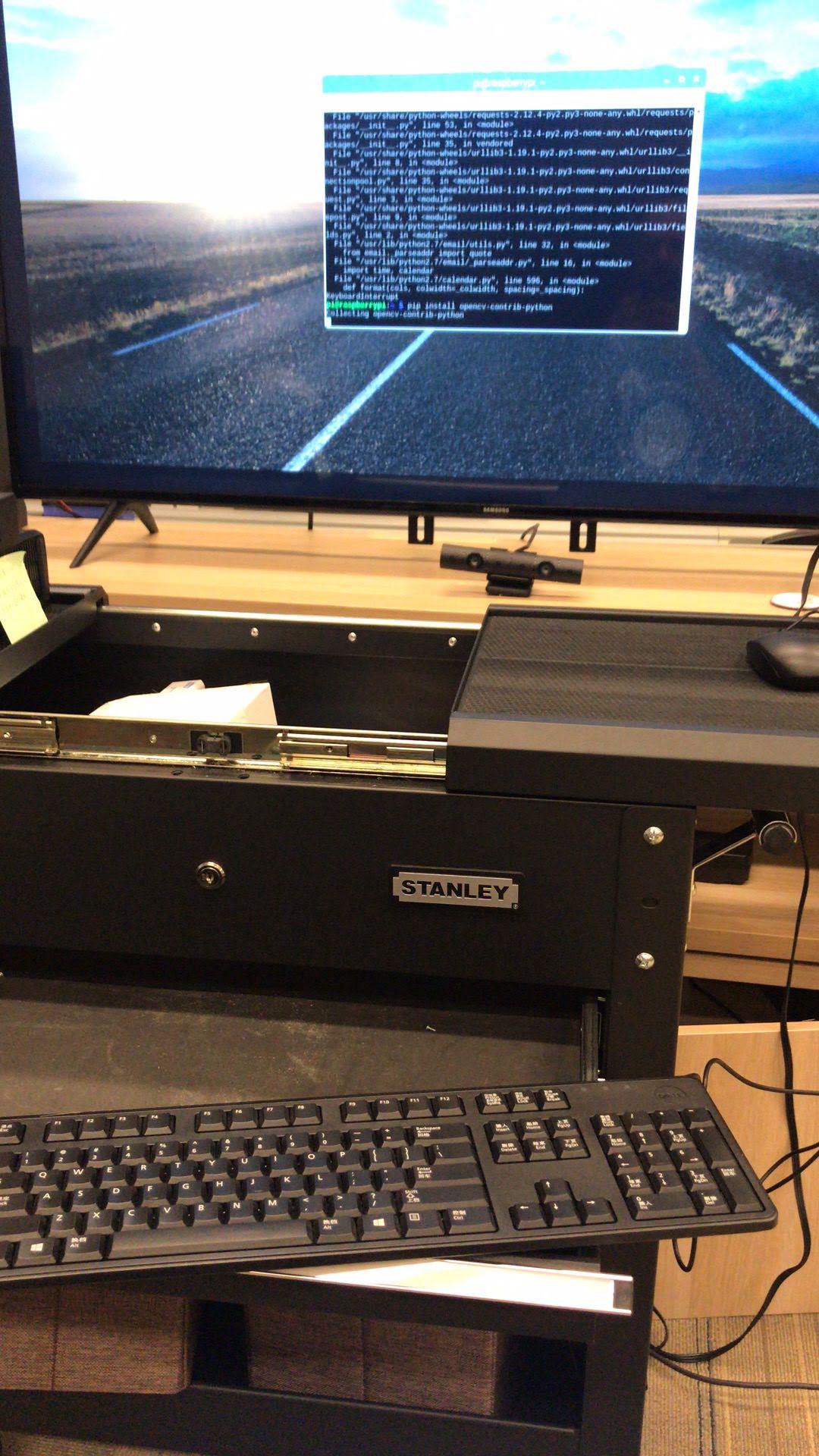
- Raspberry Pi with OpenCV
- arUco Markers transmitted by radio to micro:bit
- ESP-32 with IDF as dev environment
- ESP-32 with Arduino as dev environment
![]()
![]()
![]()
Even setting up the Raspberry Pi to work with NYU Shanghai wifi was a struggle. We were able to configure it thanks to Jack B. Du's tech documentation. Nevertheless for the Raspberry Pi 3 and for certain WiFi dongles, the drivers were also a challenge to set up.
![]()
![]()
The experience with IDF for ESP32 was not as smooth as we wished. The errors were different in the diverse OS we had and installing all dependencies seemed to be a challenge itself. After a whole day of debugging, we finally were able to blink an LED on each ESP32. This proved to be a clear obstacle for our development, where we would be forced to first become familiar with the environment.
On the contrary, we already had expertise using Arduino IDE. Setting up ESP32 with the board manager was just a matter of minutes and we quickly started coding a webserver and a set of RGB smart LEDs with the FastLED library.
It was also interesting to find that there were already WiFi mesh implementations ( easyMesh and painlessMesh). That would be great to satisfy with the requirement of scalability that WiFi alone could not satisfy if we decide to use ESP32.
![]()
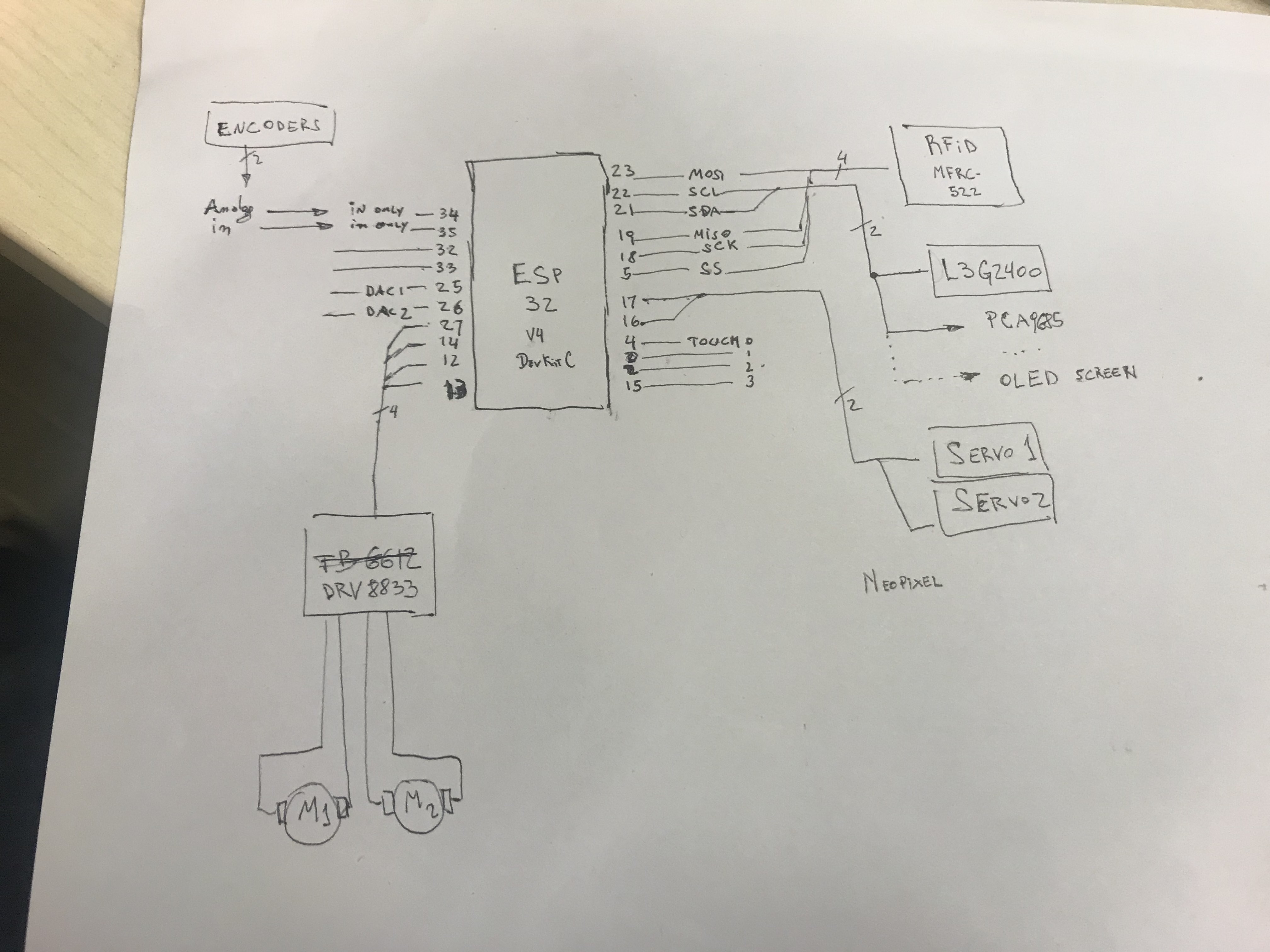
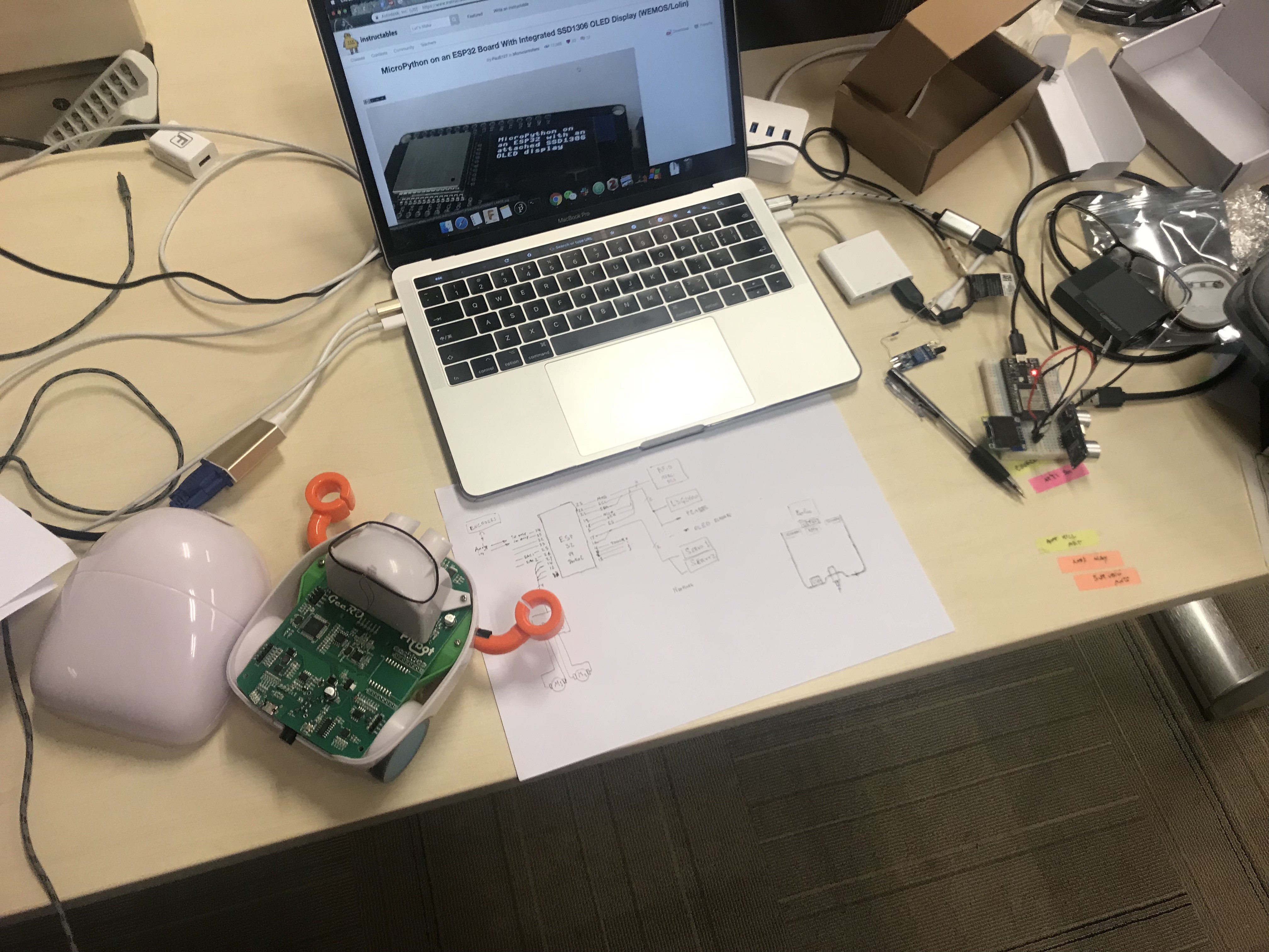
Next steps with ESP32 is to add it to a mobile platform. We are in the process of wiring WSP32 to Plobot because it has many of the sensors we need for the project.
Besides of the communication between the different robots being scalable, the relative position from each other is critical for the project. We replicated the technique of Kilobot of reflecting infrared to calculate distance.
We also explored using computer vision as an exploration to detect positions and from there calculating the distances. This worked well when using a PC (mac mini, Windows, macbook pro). The only issue was that it required to calibrate the algorithm for the specific camera and we had to handle logistics by hanging a webcam on the roof plus getting an extra long (5m) USB cable.
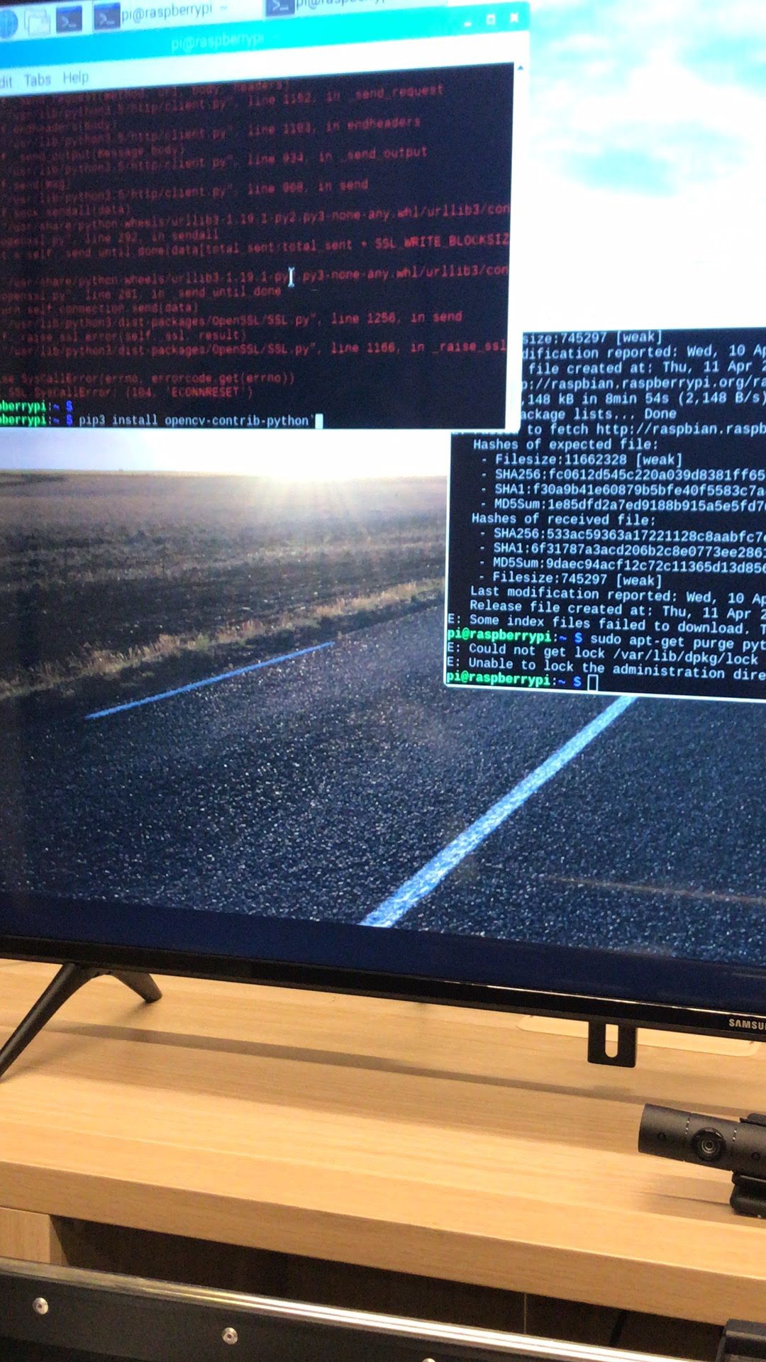
In contrast to the x86 architecture setup, it was an outstretch when we tried to set it up on a Raspberry Pi. The two reasons were that managing dependencies when moving to ARM architecture. When using RPi, we had to compile the OpenCV with the specific modules and only after that see that we had a poor frame-rate. More work should be developed
![]()
-
Log 2: More Exploration
05/10/2019 at 16:37 • 0 commentsWe did more exploration tonight. We tried out how to use Arduino to program ESP32 and control a LED matrix. Also, we improved the IR testing by reversing the wiring on the IR receiver. In the end, we tried again with the wifi connection of Raspberry Pi.
Several Things We Did:
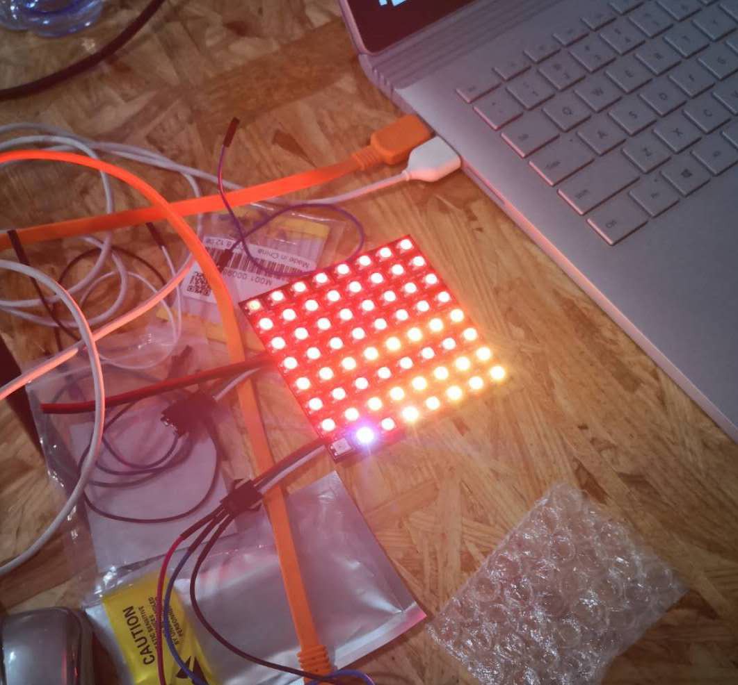
1. Using Arduino to program ESP32 and control a LED matrix
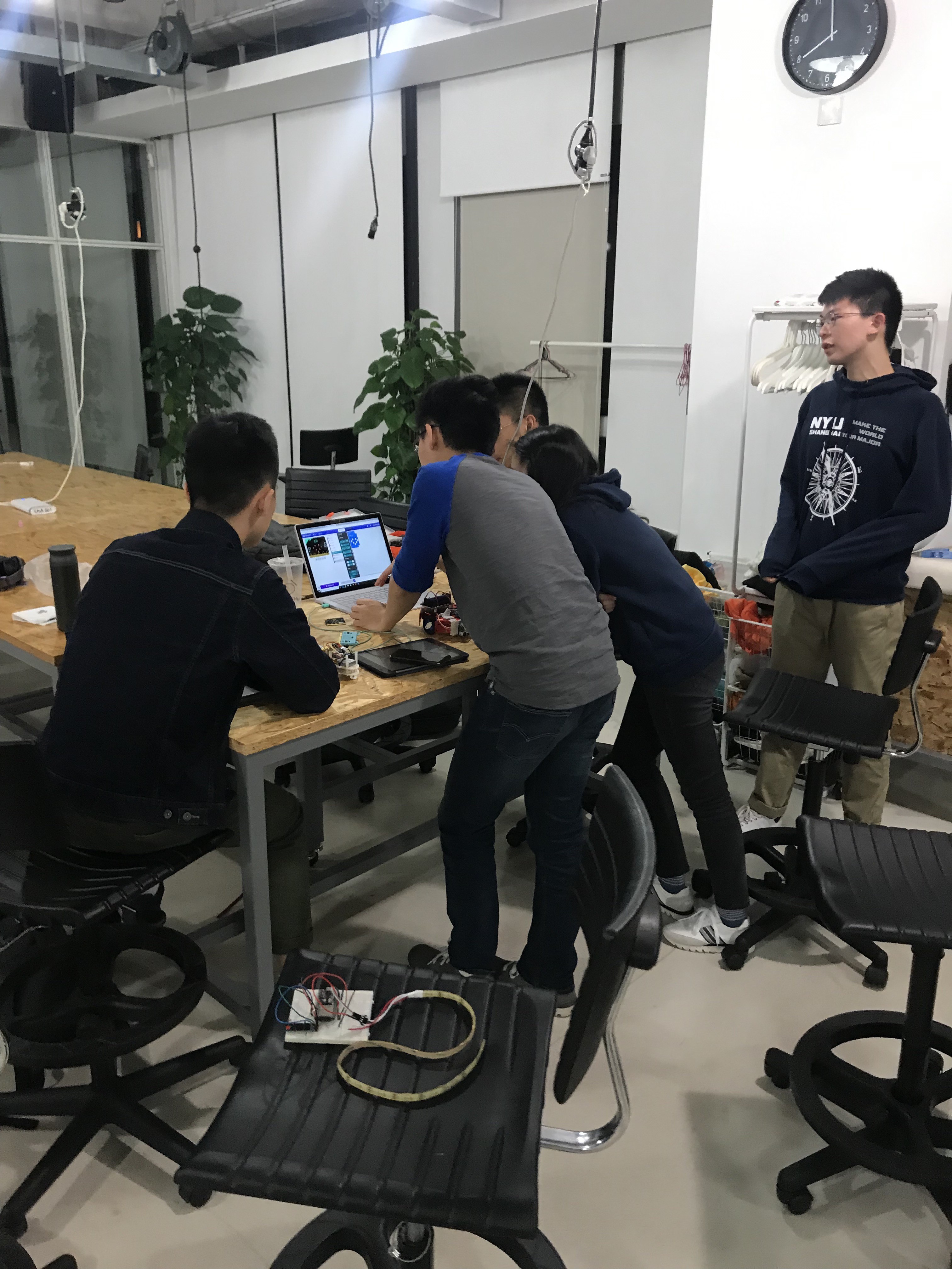
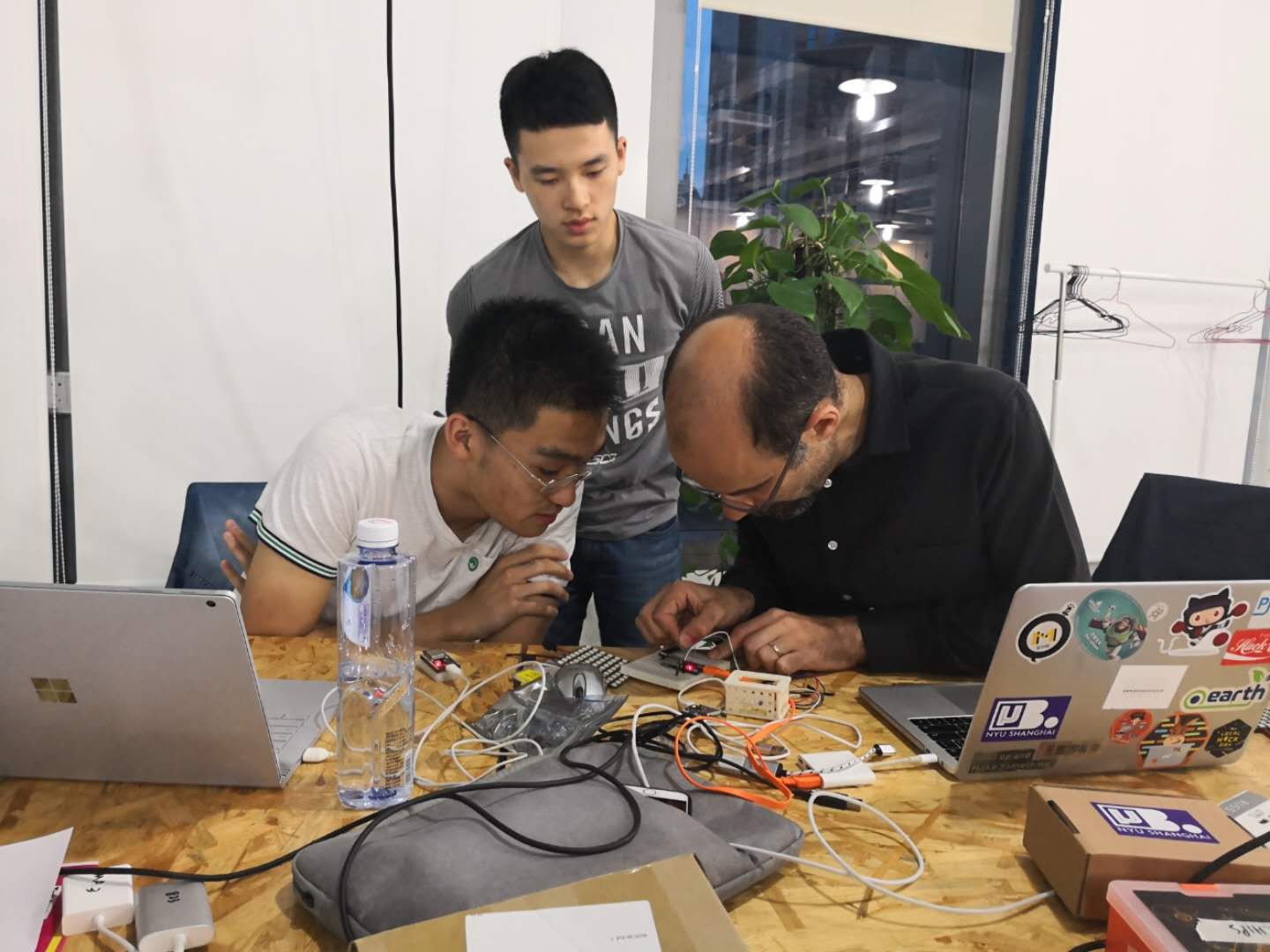
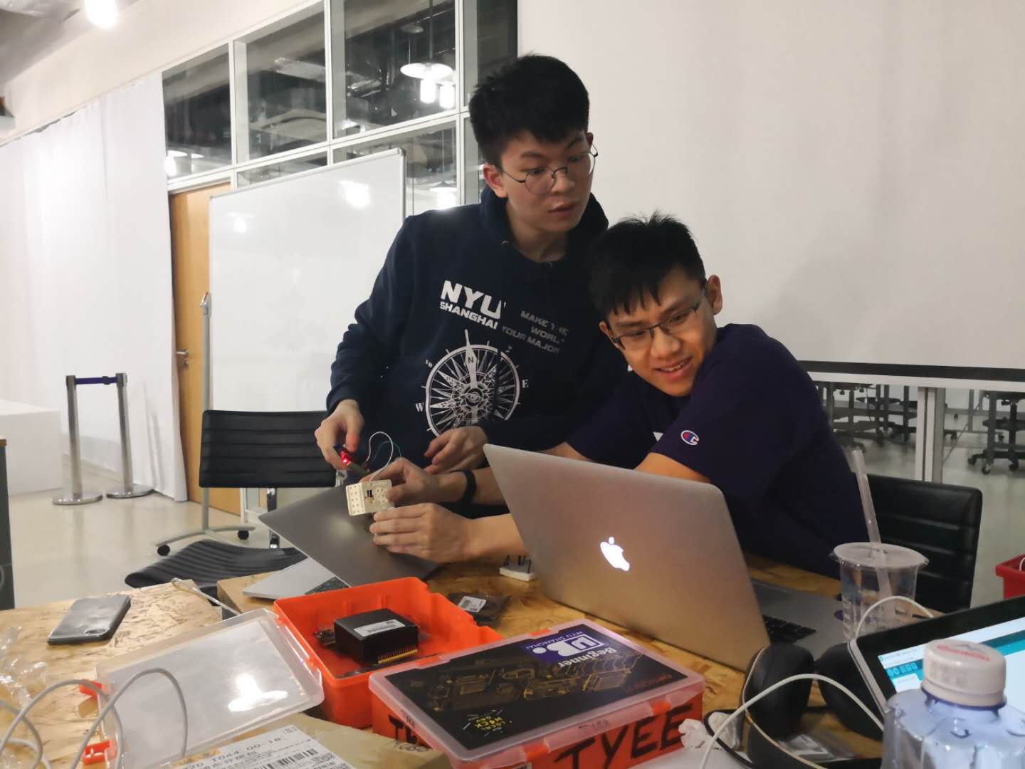
Our professor, Rudi, is teaching Benny and James how to program ESP32 using Arduino.
![]()
The work of James and Alison.
![]()
2. Improving IR testing
Thomas and Sheldon reversed the wiring on the IR receiver and made the signal caption stronger. And they also tried using conductive tape to strengthen the reflection of the IR signal.
![]()
A close-up of the transmitter.
![]()
3. Wifi connection of RaspberryPi.
Zander has tried to connect to the wifi of NYU, but it did not seem to be working. So this time, we tried to connect to a personal hotspot to see if anything different happens. Sheldon connect the RaspberryPi to his own hotspot, but for some reason, it did not work as well.
Takeaways:
Today is mostly about the hardware part.
ESP32:
1. Making good use of the Arduino Library can help one explore more about how to program ESP32.
2. ESP32 can set Wifi so that the control menu will be easier to operate.
IR testing:
1. Accidentally reversing the wiring on the IR receiver can bring a pleasant surprise! With the help of another professor, we understood why rewiring worked.
2. The reflection of IR signal requires better material then just conductive tape, but right now, we are able to catch the signal from pretty far away.
TODOS:
1. Continuing perfecting IR testing
2. Figure out why the wifi connection of RaspberryPi is not working.
-
Log 1: A Great Start
05/03/2019 at 16:18 • 0 commentsTonight has been a very productive night. We set up our working space, gathered the materials we need, started tinkering with ESP32 and set up the test circuit for IR trasmitters/receivers. Although there's still a long way to go to achieve our goal, at least we are making progress.
Several things we did:
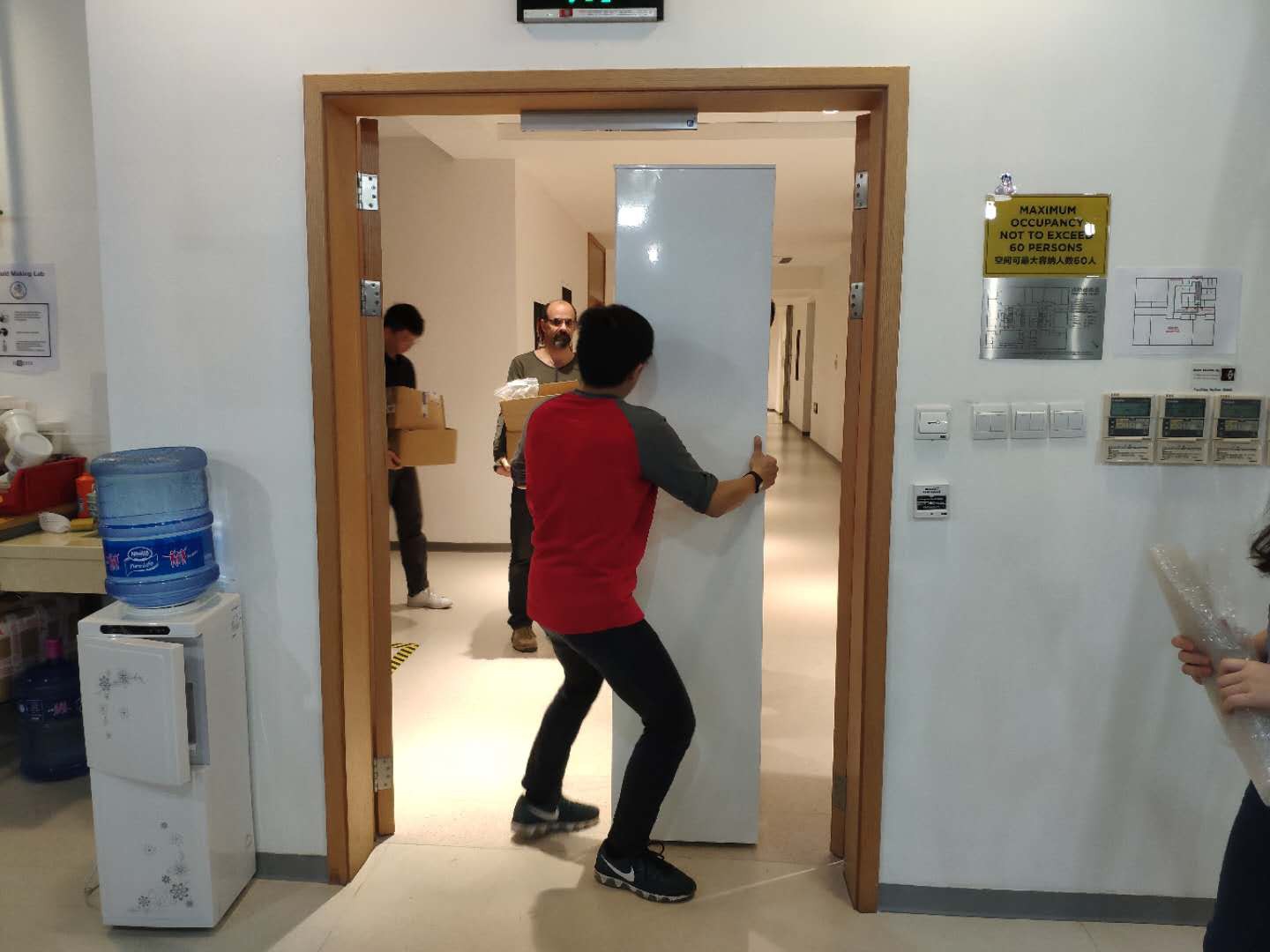
1. Set up our storage room
We cleaned up a room, move some of Rudi's robotics material and some other useful stuff (capacitors, resistors, and even an old computer!) to the storage room.
![]() Thomas moving the shelf
Thomas moving the shelf![]() Rudi and Sheldon check what's available
Rudi and Sheldon check what's available![]()
Our discoveries
2. Set up ESP-IDF
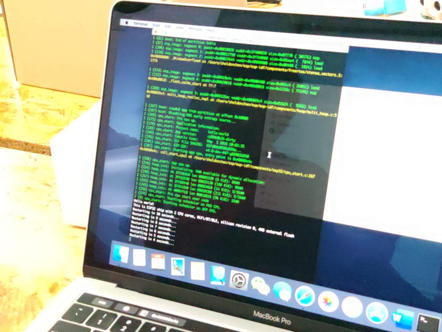
It took us a long time to set things up, but eventually Sheldon, Alison and James all can upload examples to ESP-IDF. That's a great start.![]() ESP32 running hello_world example
ESP32 running hello_world example3. Set up IR testing
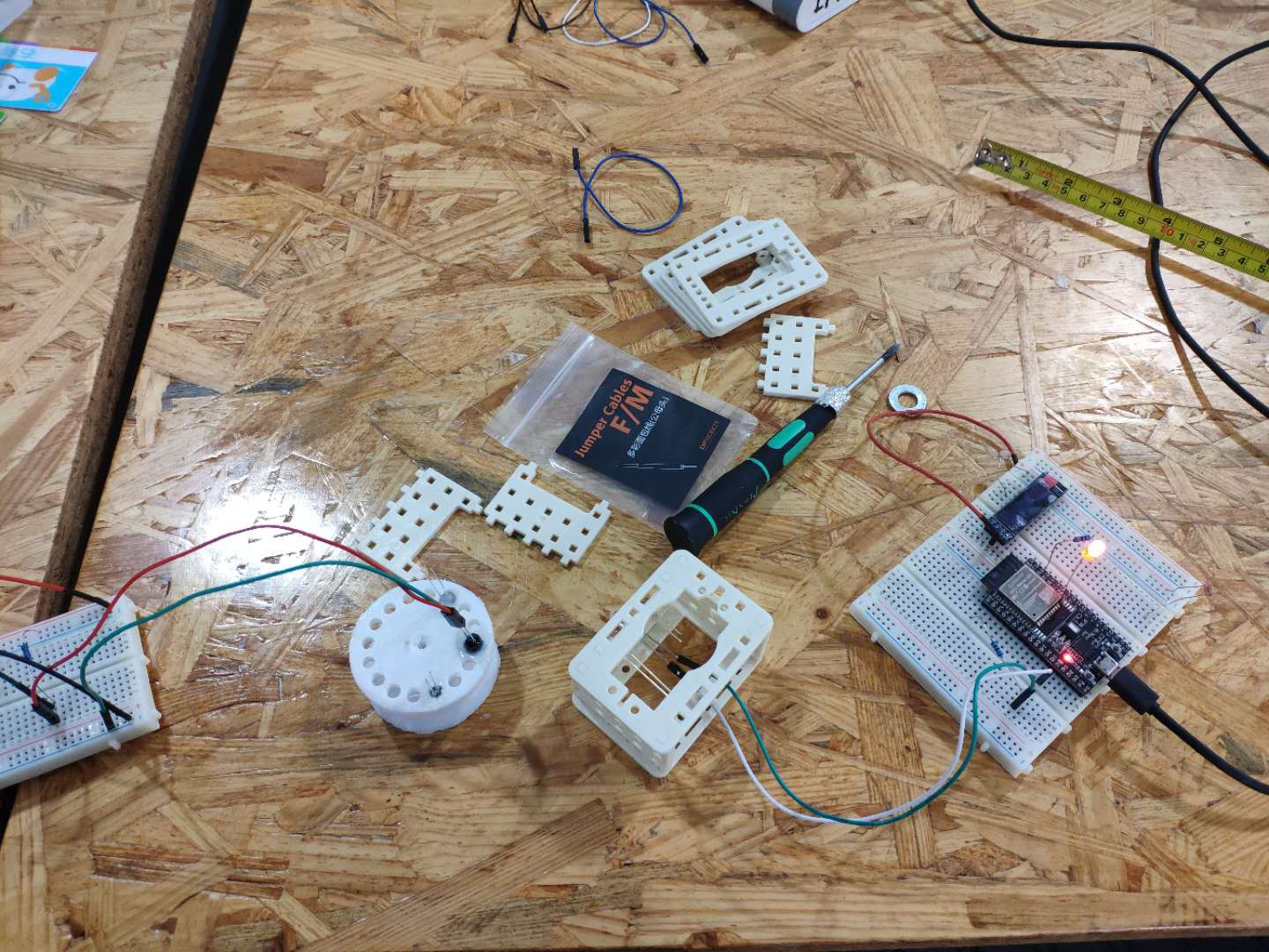
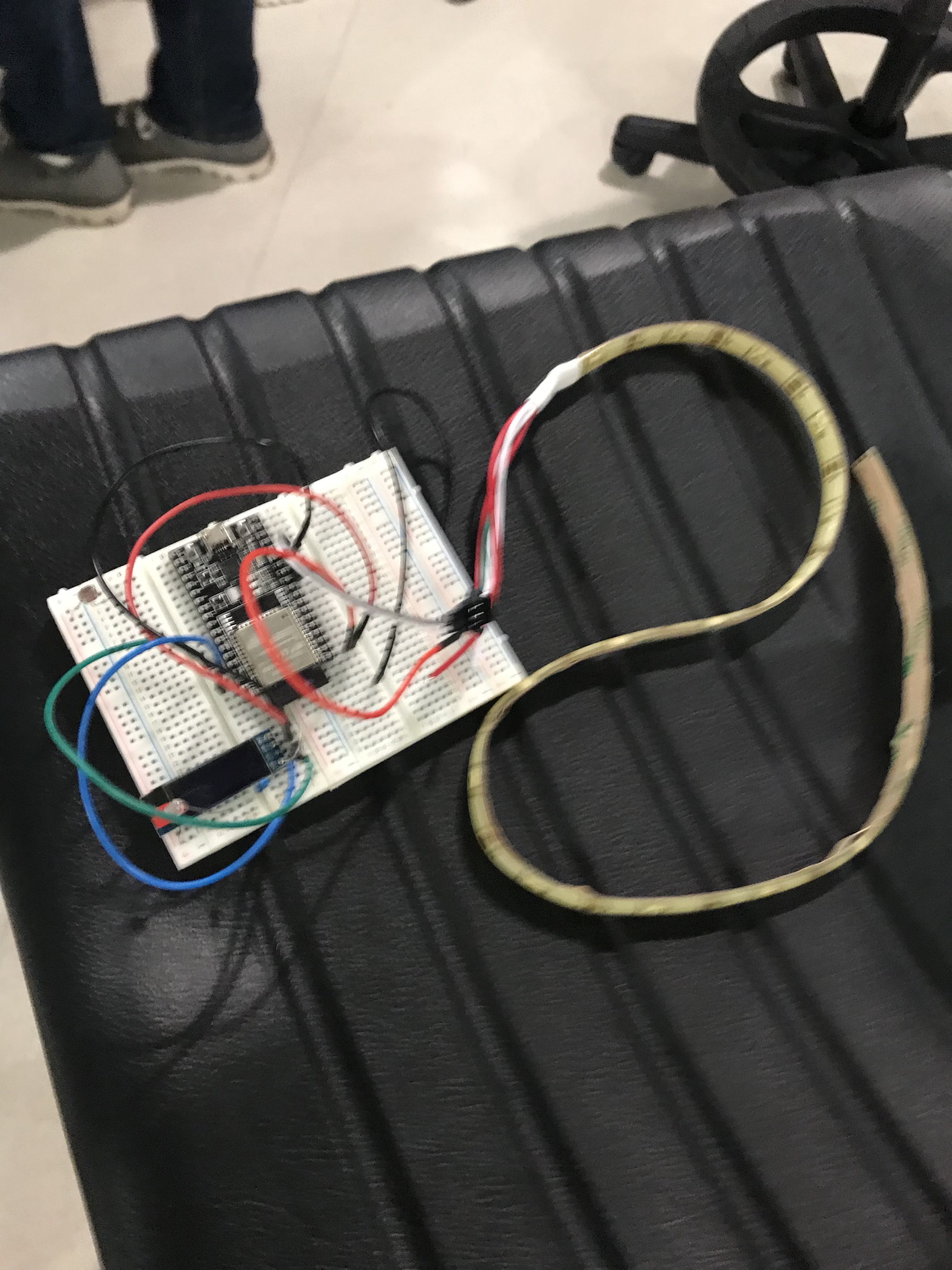
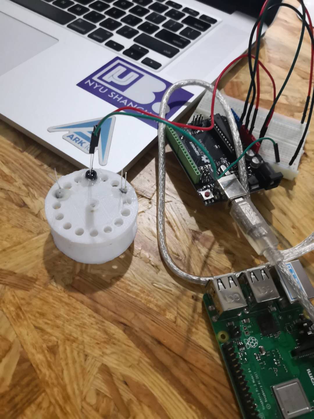
We set up the circuit to test how IR receiver/trasmitter work. We read the analog output of the IR receiver using an Arduino and used ESP32 as a power (no special reason, just because it's there). For now it doesn't work very well, but we'll try to improve that later.
![]()
Prototyping IR test
![]()
Circuit Provided by Rudi
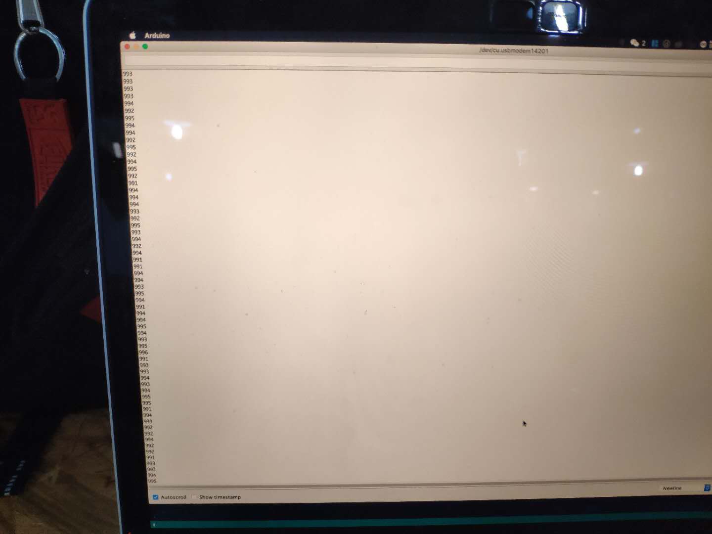
![]()
Preliminary Result, We read something, but not sensitive enough
![]()
Test Plaform. IR receivers/trasmitters are glued to the plastic pieces.
Takeaways:
Basic Linux Command:
ls: list all the file under current directory
cd /children/path: change directory to childern path
cd: go home
cd .. : go back to the parent folder
cp -r /file/you/copy /where/you/want/to/put : -r is a flag indicating recursive, meaning recursively copy every file and every subfolder in the directory you copied.
chmod (*number) /directory: change users' permission to modify a file. Usually there are three numbers, which stands for the permission for the file owner, group and others. Translated in binary, each of the numbers corresponds to the status for three different kinds of permission: read(r), write(w), execute(x). For example, if I set some folder by typing chmod 777 /folder/path, it will be for file owner, group and others, the permission will be 111 (7's binary representation), which means they will be able to read, write and execute the file. If I set them to 444, all of them will only have the permision of 100(4's binary reprpesentation), which means they can only read.
export IDF_PATH=/your/idf/path: set IDF_PATH
mkdir: make directory
cat: peek into file
ESP-IDF configuration:
1. clone from https://github.com/espressif/esp-idf.git
2. set IDF_PATH to where you cloned the project : export IDF_PATH=your/path/to/esp/esp-idf
3. add tool chain path to the PATH variable: export PATH=your/path/to/esp/xtensa-esp32-elf/bin:$PATH
4. Go to project folder, use make menuconfig to set up ports to upload. By default it's ttyUSB0, but on Mac it might be ttyUSBtoUART (something like that). The chip uses a silcon lab CP2102 chip to handle serial communication, so probably a driver for that is needed.
One more thing about ESP32:
It has analog output (PWM) when using Arduino IDE. For simplicity, we will explore that way of programming.
TODOs:
1. Improve IR distance test
2. Look into VSCode plugin "PlatformIO IDE" and try to simplify the steps to connect.
Swarmesh NYU Shanghai
Scalable swarm robot platform using ESP32 MESH capabilities and custom IR location


 If the size of the data is too big, the latency will be high.
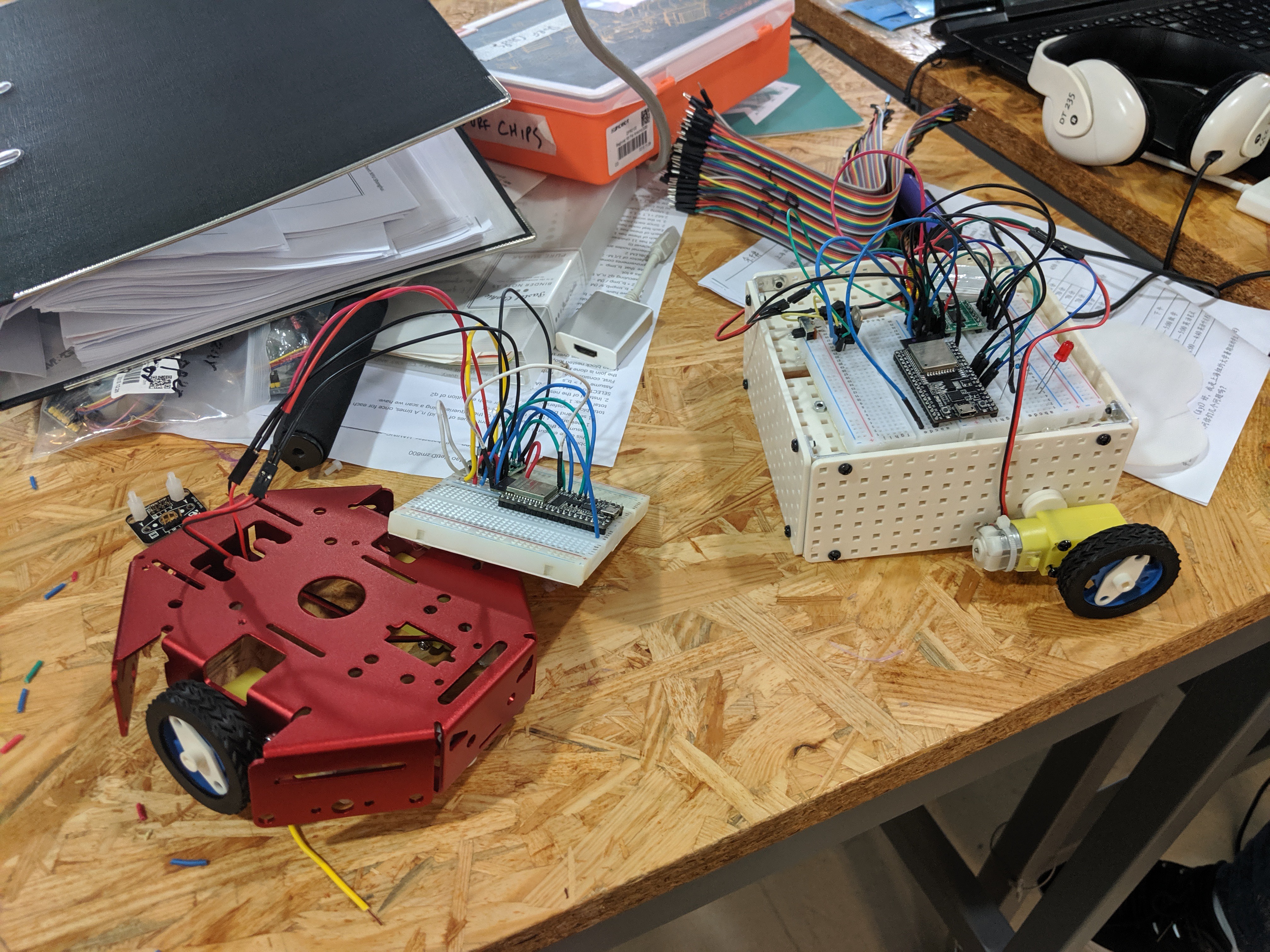


 Thomas moving the shelf
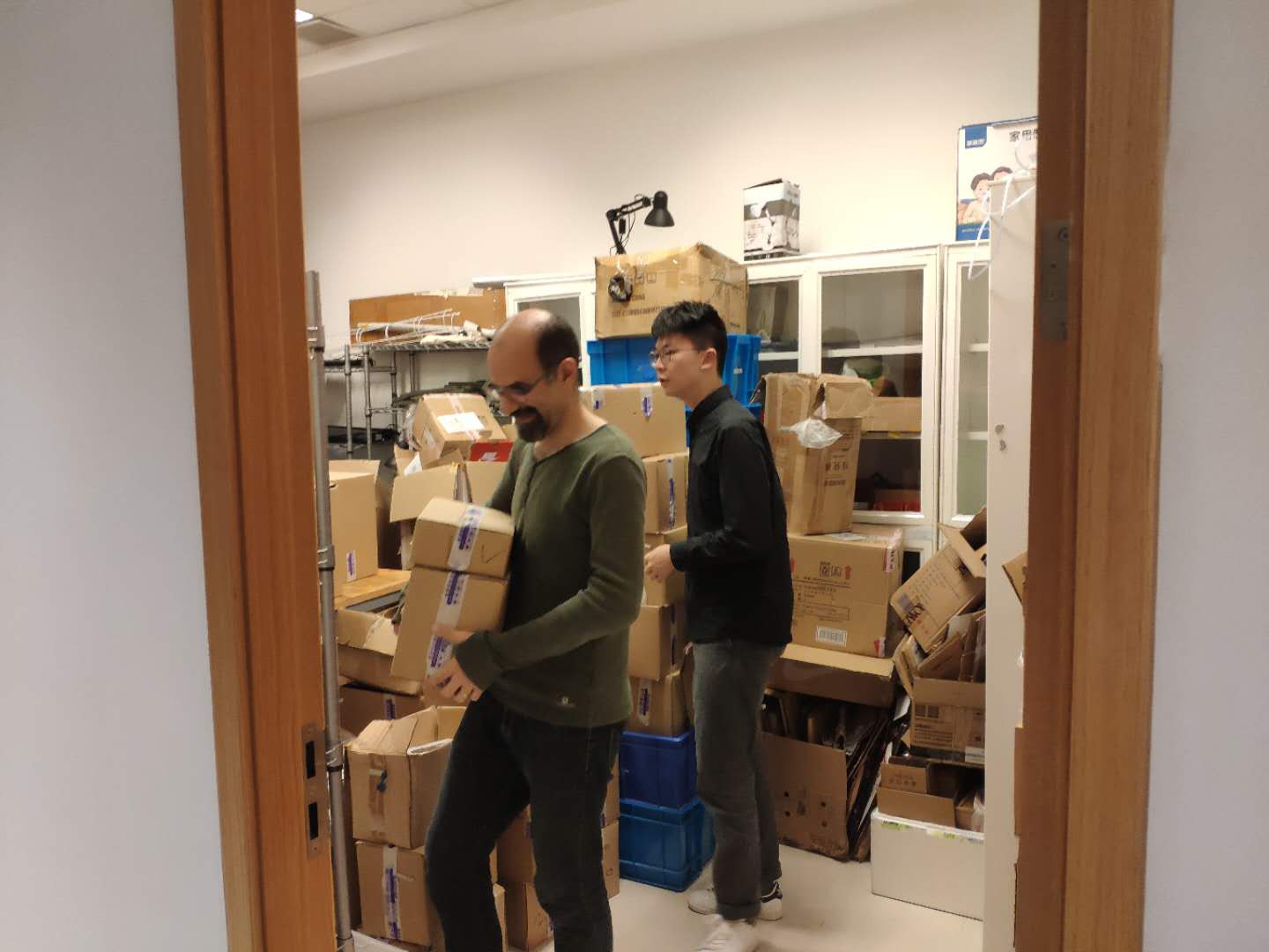 Rudi and Sheldon check what's available
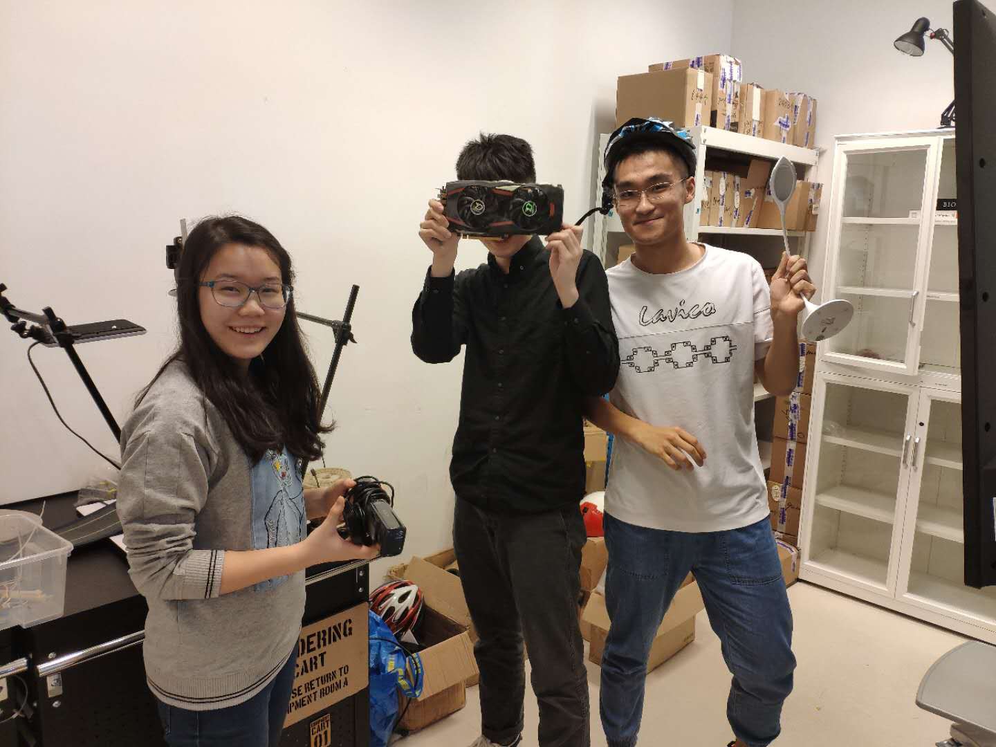
 ESP32 running hello_world example