 Jana Marie
To drive the LEDs, we need two boost converters from VBAT (3.2V-4.2V) to VLED (~10V-16V). Since I want to keep the costs as well as the number of components low, I decided for a processor, which can implement the Boost converter in software.
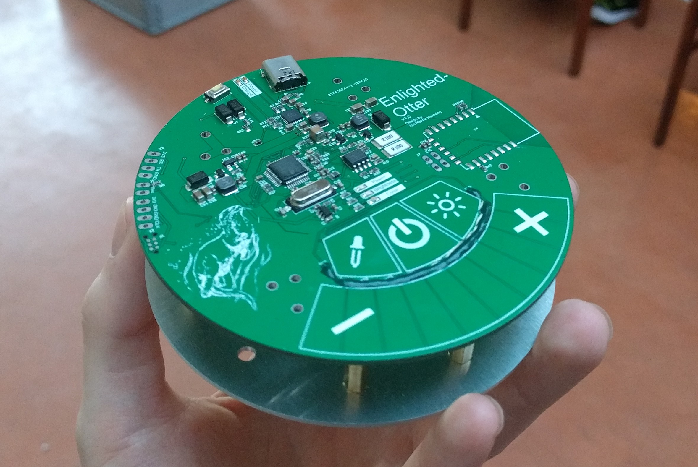
The STM32F334 has a timer with a clock frequency of 4.6Ghz*, comparator inputs, reasonable ADCs and a touch controller. So I get PWM at 500kHz with a resolution of >13 bit. The ADCs are needed to regulate the LED current via the boost, the comparators are used to stop the boost in a fault condition in shortest time without software interaction.
A schematic can be found here.
I want to use the Touch controller (TSC) for the input of Enlightened Otter. Beside a slider I need three buttons (on/off, brightness, color temperature). This allows you to distinguish between brightness and color temperature and adjust them with the slider. To save pins I implemented a resisitive interpolation of the touch slider. Thus three pins result in a slider with a resolution of > 300 points (measured). Atmel has a good application note on this topic. Unfortunately the interpolation resistors are a source of error if you touch them, so I put a solder resist mask as insulation/protective lacquer on them.
* Of course the STM doesn't have a 4.6Ghz clock, but 32 144Mhz clocks with phase-shifted timers.
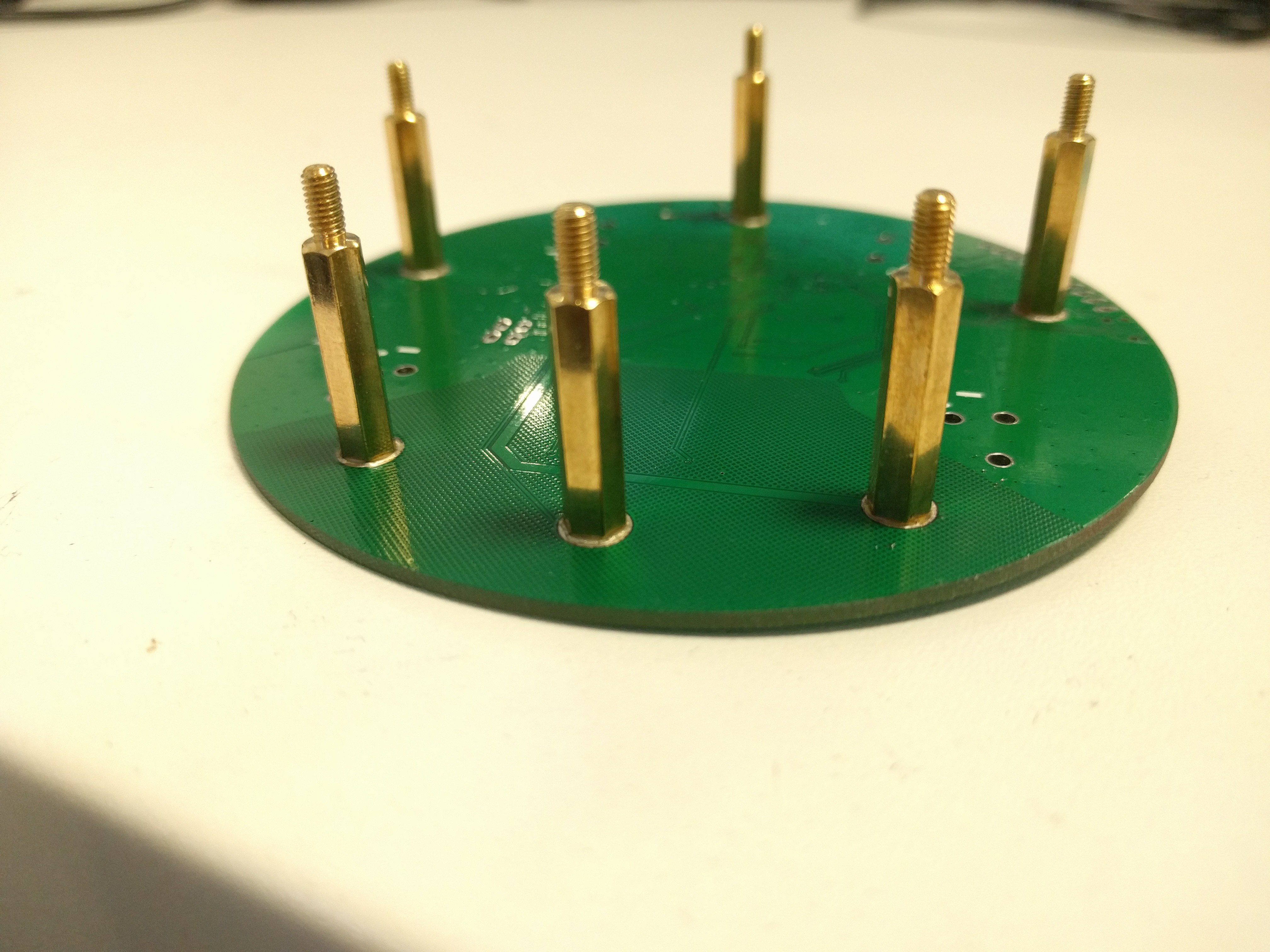
On the backside of the PCB spacers are soldered as SMD to connect both PCBs, so I don't have screw holes on the topside. Unfortunately this is also rather fiddly, spacers tend to fall over when soldering.
As battery connector I used "Keystone 54", they have the smallest footprint available for 18650 type cells.
Discussions
Become a Hackaday.io Member
Create an account to leave a comment. Already have an account? Log In.