 Jac Goudsmit
DCC recorders are complicated devices. But the service manuals and datasheets that are available online give great insight into how a DCC recorder works in general. They also give many subtle hints about how we could teach them new tricks.
Here's a list of the things that I want to make my recorders do:
- Extract text information such as song titles
- Extract audio in PASC-encoded format
- Store a cassette dump on an SD card inside or outside a recorder
- Play a dump file as if it's a cassette
- Record a dump file to a cassette
It will take a lot of effort to do all this, but I'm pretty sure the information to accomplish it is all publicly available. What I first need to do is figure out some details about how a recorder works, and find a way to improve it.
Third Generation DCC Recorders
The DCC-730 and DCC-951 "third generation" recorders were released around 1995, and by then, Philips were getting very good at making DCC recorders in a highly modular way. They released a System Description document that describes the Third Generation DCC system, and the following is roughly the same information in my own words, with extra focus on the parts that I need to use or modify for this project.
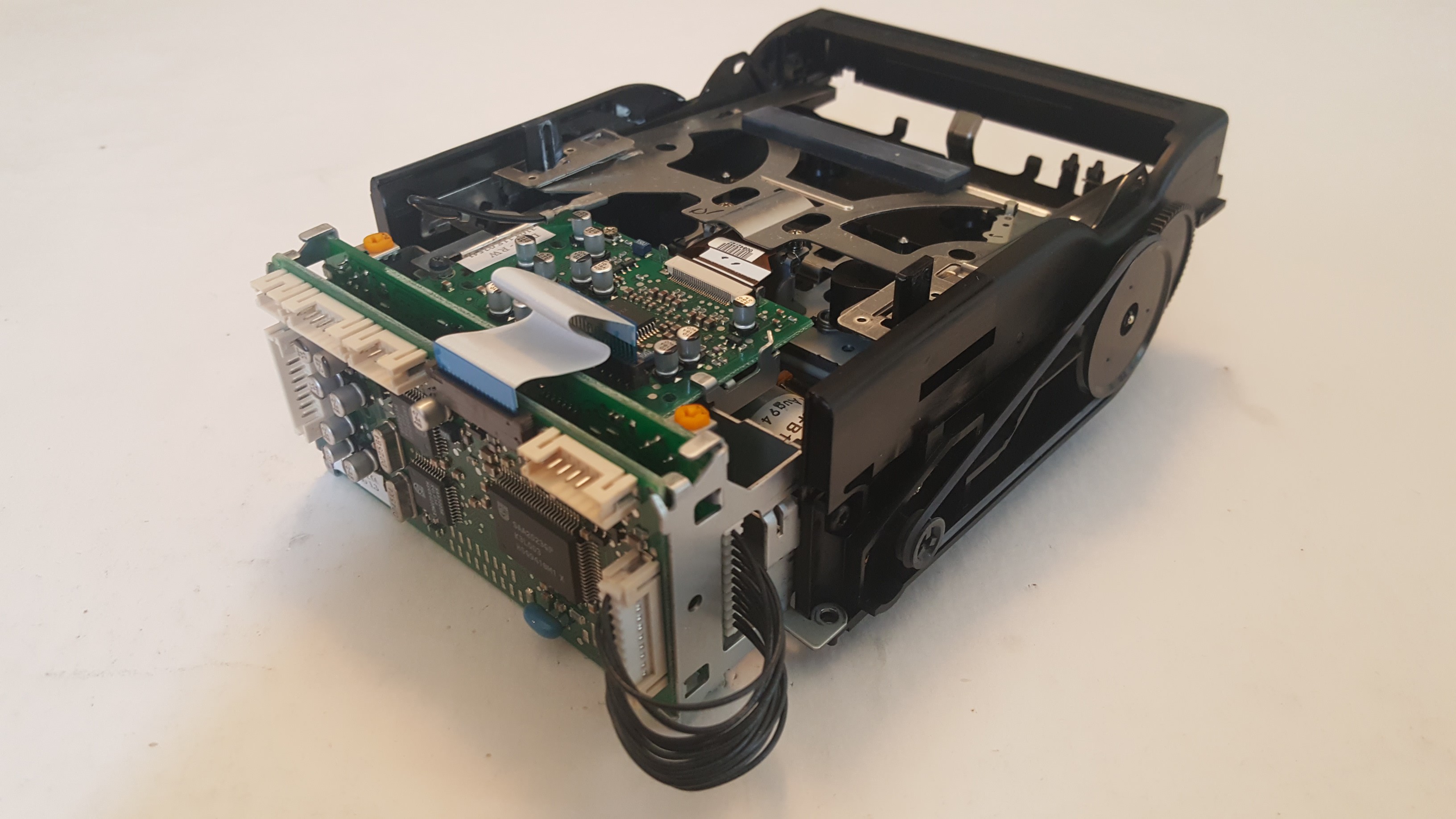
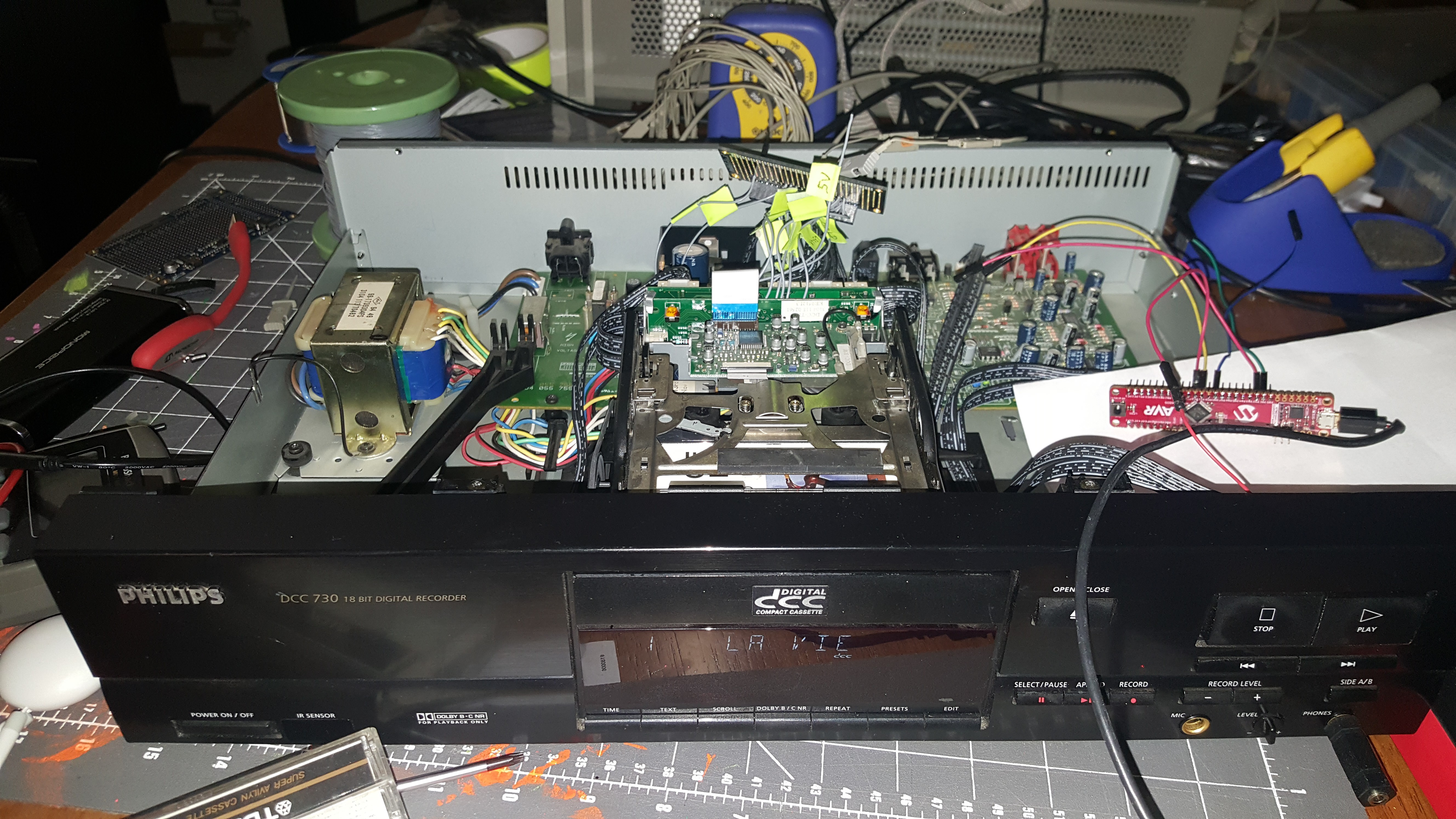
The heart of the 3rd generation recorder is the DDU-2113 Turbo Drive mechanism shown above. The DDU (DCC Deck Unit) is pretty much a standalone unit. In theory, if you would want to build a DCC recorder around a DDU, all you would need is:
- A power supply,
- A front panel with buttons, display and a microcontroller (and probably a receiver for remote control commands),
- Optionally, some digital (S/PDIF PCM, a.k.a. IEC-958 a.k.a. IEC 60958) audio inputs and outputs,
- Analog audio inputs and outputs.
Philips made two DCC recorders with the DDU-2113: the DCC-730 and the DCC-951. They also used the same electronics in the FW68 mini-set but because that unit doesn't have digital inputs and outputs, they left a chip and a connector unpopulated.
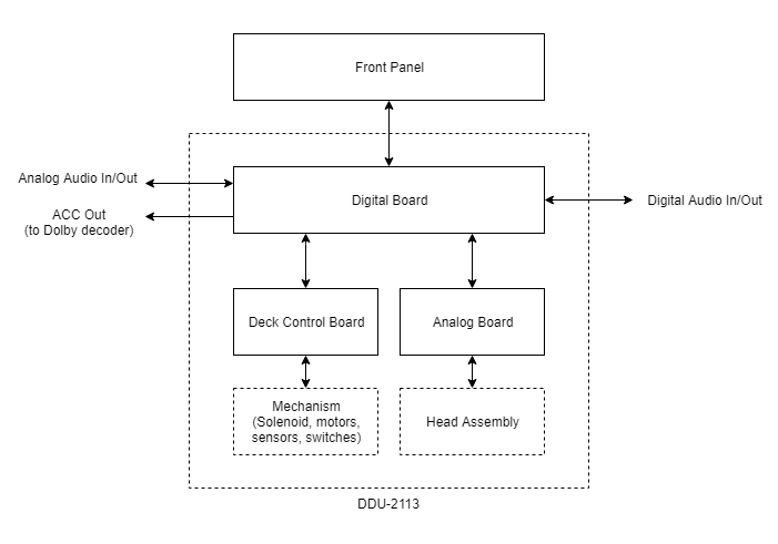
The block diagram above shows that all the essential electronics for an entire DCC recorder are on the DDU:
- The Analog board amplifies the signals to and from the heads
- The Deck Control board operates the mechanism
- The Digital board does... everything else!
Let's have a closer look at the Digital Board.
The Digital Board: The Heart of the DDU
The Digital Board is on the back of the DDU and it's what connects the DDU to the outside world.
- During DCC playback, it reads the bits from the tape via the Analog board. It performs error detection and correction, converts the PASC (MPEG-1 Layer 1) compressed audio stream to PCM, and converts the PCM stream to S/PDIF (IEC-60958) and analog audio
- During DCC recording, it converts analog audio or PCM digital audio to PASC, adds codes to help with error detection and correction, and records the bits to tape via the Analog board
- It communicates with the Deck Control board to change the state of the mechanism: Stop, Play/Record, Fast-Forward, Rewind, Search-Backwards or Search-Forwards, Drawer-open/close...
- It communicates with the Front Panel to receive commands from the user (buttons or remote control) and show text on the front panel screen.
- It can perform more complicated tasks too, such as recording and detecting markers and renumbering a cassette.
- When playing an analog cassette, the output signal from the Analog board is sent directly to the special ACC outputs which are connected to a Dolby decoder on the motherboard. The outputs of the Dolby decoder are looped back into the analog input of the ADC so that digital output is available for analog cassettes as well as DCC.
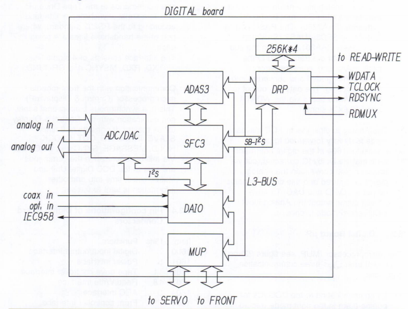
The most important chips on the board are as follows:
- The Main Microcontroller (MUP) communicates with the front panel and the deck control board, and controls all the DCC custom chips.
- The Drive Processor (DRP) processes the signals from the analog board to a PASC encoded audio stream (and other data on the tape) and vice versa.
- The Sub-band Filter and Codec (SFC or SFC3) converts PASC to PCM and back (with the help of the ADAS, see below).
- The Adaptive Allocator and Scaler (ADAS or ADAS3) is used during recording to reduce the bandwidth of the audio stream.
- The Analog to Digital Converter (ADC) converts analog audio to (PCM) digital audio
- The Digital to Analog Converter (DAC) converts (PCM) digital audio to analog audio
- The Digital Audio Input/Output chip (DAIO) handles up to two digital (IEC-60958) inputs and also generates a digital (IEC-60958) output; on the FW-68, this part is not populated.
Buses on the Digital Board
MUP control buses
The MUP has three buses:
- The Front Panel microcontroller is connected to the MUP through a synchronous serial port with a protocol that resembles SPI.
- The MUP communicates with the deck controller through a TTL serial port.
- All the other chips on the Digital Board (except the DAC and ADC) are connected via the "L3 Bus".
The L3 bus is a synchronous serial bus with 3 lines: Clock, Data and Mode.
- The Clock line is used to shift data in and out. The MUP generates the clock.
- The Data line carries the data both from the MUP to the chips and vice versa. There is only a single data line because only one chip at a time is allowed to put data on the bus.
- The Mode line is used to distinguish commands from other data. There are no chip-select lines like with a SPI bus (or like the LT bus in earlier DCC recorders which is partially compatible with the L3 bus): When the master issues a command, all other chips go into a listening state (regardless of what they were doing before). Commands are unique between all the chips on the bus, so there's always only one chip that understands each command and possibly sends data back when the Mode line goes HIGH again and clock signals are issued. The other chips sit idle until they detect a command that they recognize.
The datasheets for the chips describe each command very accurately; it's almost like the engineers at Philips wanted us to build a DCC recorder for ourselves :-)
Audio buses
Besides control buses, there are also three I2S buses:
- Between the ADC, the DAC, the DAIO and the SFC, there is an I2S bus that carries PCM stereo audio at 32000, 44100 or 48000 samples per second. All those chips are capable of handling 18 bits per sample.
- Between the SFC and ADAS, there is a special I2S bus that carries uncompressed sub-band audio during recording (only): the SFC filters the audio into 32 equal size sub-bands of frequencies and sends the information to the ADAS which then determines which parts can be dropped because they can't be heard anyway. The ADAS then sends the data-reduced stream back to the SFC which forwards it to the DRP.
- Between the SFC and the DRP is the Sub-Band I2S bus (SB-I2S) which carries the PASC compressed data during recording and playback. The format of this stream is described in the SFC and DRP datasheets: the bus always runs at 768 kilobits per second, which is twice the fixed data rate of 384 kbps, but the bus only uses half the bandwidth.
How It All Comes Together
You should now have some idea of how the most important parts of the DDU work. For further details about parts that I didn't go into, see the documents that are linked in various places. You can also post a question or contact me of course!
As you may have figured out, the DRP and MUP are the most important chips on the Digital board. The DRP determines what goes on a tape, makes it possible for the MUP to extract information such as song titles and does a bunch of work "under the hood" to take care of formatting the tape and correcting problems at playback time. The MUP puts all the chips in the right mode and tells the deck controller to do the things it's supposed to do.
You could say that the MUP knows all the tricks that the DCC recorder can do. So to teach the recorder new tricks, you'd have to modify the program that's stored in the MUP. Unfortunately it's not that easy, for many reasons:
- The source code to the program in the MUP is not available and there is no expectation that Philips would make the source code available in any way if they even still have it.
- The binary code is also not available and I wouldn't know how to extract it, besides maybe hand it off to someone who has experience with decapitating integrated circuits to read the ROM. Even if that would be a practical solution, it would be difficult to analyze the ROM contents and disassemble it.
- Even if I could somehow get source code that I could modify to improve the programming, it's not possible to store that code into an existing MUP because it uses ROM. So I'd have to use a different chip to replace the MUP.
- The MUP is a NEC (now Renesas) "78K" microcontroller and EPROM versions of that chip exist but I don't know how easy it would be to get them. Also, there are no freely available development tools for it such as compilers, linkers, debuggers and hardware to download programs into the chips.
- Additionally, there are probably reasons why things were implemented in a certain way (that we may not like) in the first place: maybe some things just couldn't be done because there wasn't enough space in the ROM. Maybe the microcontroller just wasn't fast enough to do certain things. All those things I wouldn't be able to solve even if I could possibly solve the other problems mentioned above.
- I could replace the MUP with a different microcontroller, running a program that was written from scratch, based on the information that's available in the datasheets and service manuals. However, no matter how long I work on reverse-engineering the existing hardware, there will always be a chance that I'm overlooking something and that my software won't be able to handle. Besides, desoldering and replacing a chip goes way beyond how far I want to go to modify a DCC recorder.
For now I think a better approach is to use the existing MUP for normal operations, and intercept when we want to do something special.
I am Locutus
The schematic gives some good hints about how it would be possible to use the MUP for normal operations, and switch it off to do special things: just put it to sleep. When the MUP is asleep, it goes off the L3 bus (and the other buses) and all pins go to high-impedance mode. A number of pull-up and pull-down resistors make sure that the other DCC chips are put to sleep.
The MUP goes to sleep when you send it a STAND BY command from the front panel (to be precise: when you send that command from the remote control). So the plan is to inject a STANDBY command into the Front Panel communication bus, just like the Enterprise crew did when they fought the Borg.
Once the MUP is offline, my microcontroller can take over the functionality of the MUP. Obviously this will take some reverse-engineering: I need to be able to take over (at least) the most basic functionality while the MUP is offline:
- Control the deck through the Deck Control serial port
- Answer commands from the Front Panel
- Control all the chips as necessary
- Wake the DDU up when I'm done, probably by resetting it
When the MUP goes offline, it's likely that it sends some commands to the Deck Controller and the chips to make them shut down in a coordinated way. Obviously I have to make sure that those commands never reach their target and that the MUP gets any expected responses to those commands.
Can You Hear Me Now?
Once I have control over the buses that are connected to the MUP, I should be able to control the deck, and inject and extract text information via the L3 bus. But the audio doesn't go through the MUP, so to extract the audio from a tape or record new audio to a tape, I'll have to do other things.
Extracting PASC audio from a tape is possible with a modern microcontroller with an I2S bus: I would just have to lock the microcontroller to the DCC bus clock and connect the data to the sub-band bus of the DCC recorder. That's not too hard (though it will probably require soldering), but allowing my microcontroller to inject audio may be more difficult because the SFC is directly connected to the DRP and they determine which way the sub-band I2S bus flows.
Fortunately the data pin for the sub-band I2S bus on the SFC is on a corner, so maybe it will be possible to desolder a leg of the IC and connect my system to both the leg and the circuit board. That way my microcontroller is the boss over the bus.