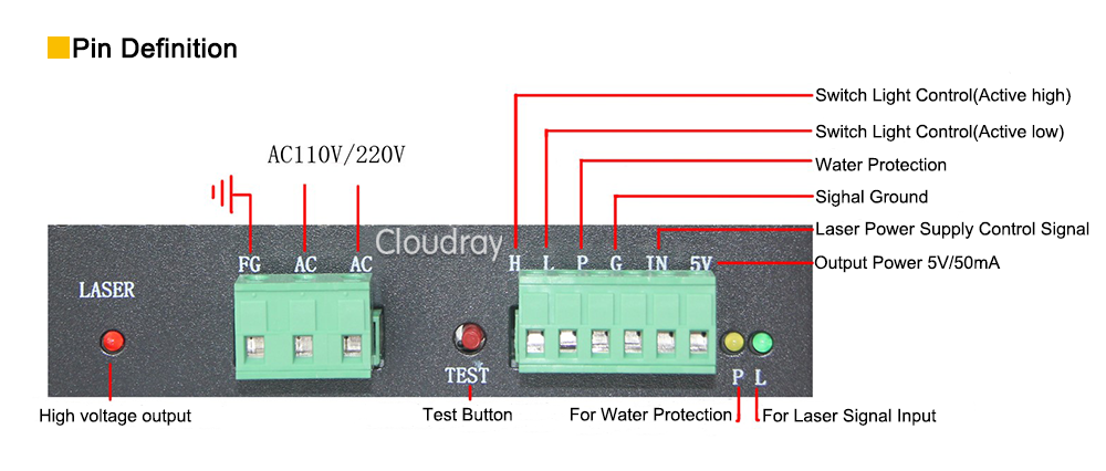
Like everything on this laser, it is very difficult to get any documentation for the PSU.
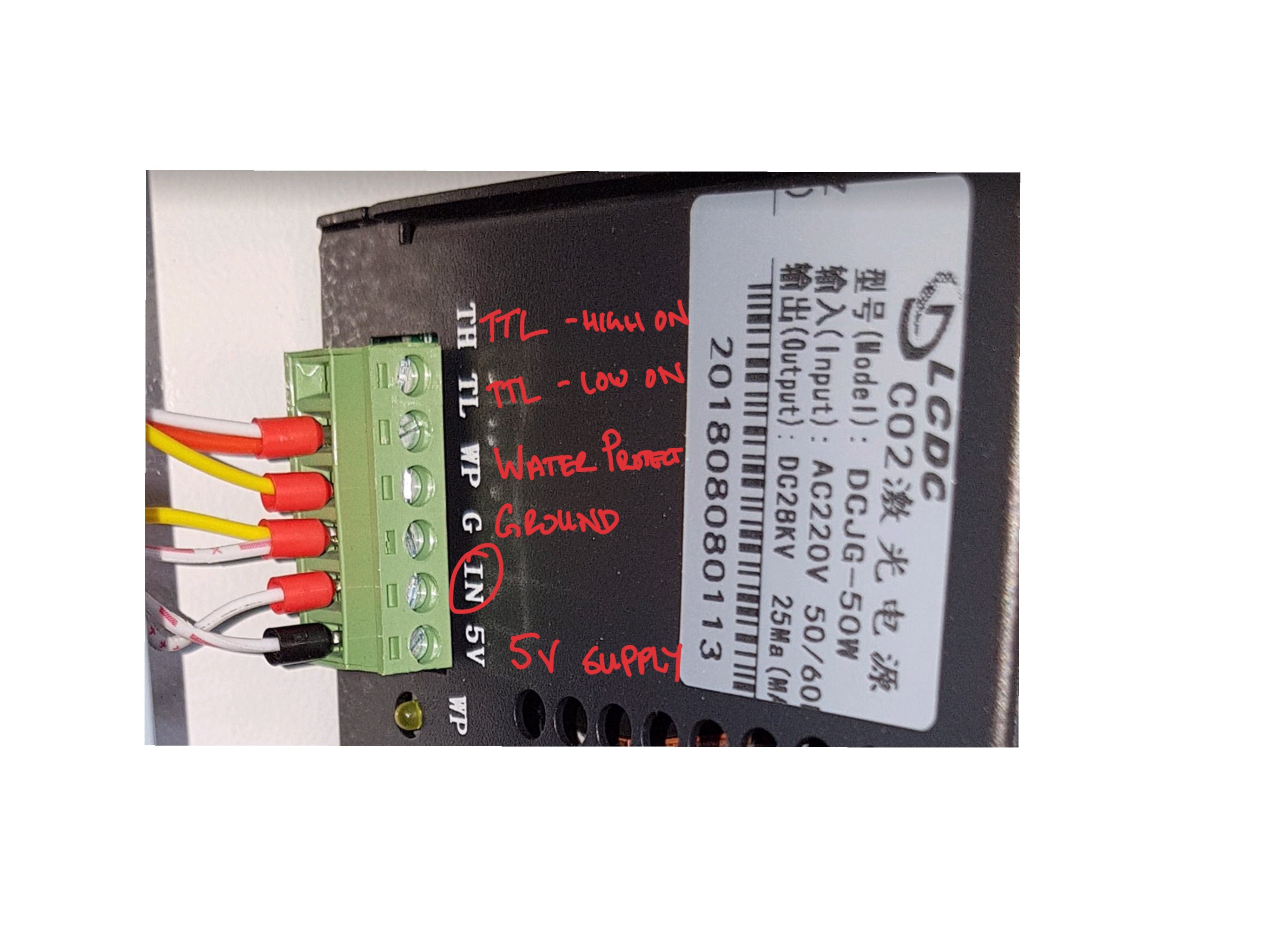
Based on the markings it is a LCDC DCJG-50W. The photo below shows the low voltage connector. I will leave the high voltage connector to the laser allone.
Out of the box, it is setup as shown in the photo below. The laser intensity is controlled by the IN pin. The power controller on the front panel provides a signal 0 to 5v (or PWM?) and the laser power is adjusted accordingly.
I think that the TL pin is connected to the "test" button and the laser is on when it is pulled to ground.
I plan to connect the spindle / laser PWM from controller to the TH (high on). I think that i should still be able to use the TL pin for testing but i am not sure what the power level will be if the IN is not connected. Maybe I should have a voltage divider pot next to the test button so that I can set the power with that. I'm Not sure how that will affect the power during normal operation though. I might need to do some testing.
I also spoke to the supplier of my laser cutter about max power that I can run the laser tube at. He said 25mA so hopefully i can find a way on the PSU to limit the current accordingly
Finally, I have been reading all over the internet about installing a ammeter in series with the laser tube to make sure that I am not exceeding the rating so i think that i will do that to. I am a bit worried that it may affect the operation of the laser. i have seen that some of the lasers have the ammeter fitted in the factory so maybe is to not a problem. let me know in the comments if you have any experience.
I'm also not sure if there should be some sort of "laser enable" pin that i need to connect to the controller.


Discussions
Become a Hackaday.io Member
Create an account to leave a comment. Already have an account? Log In.