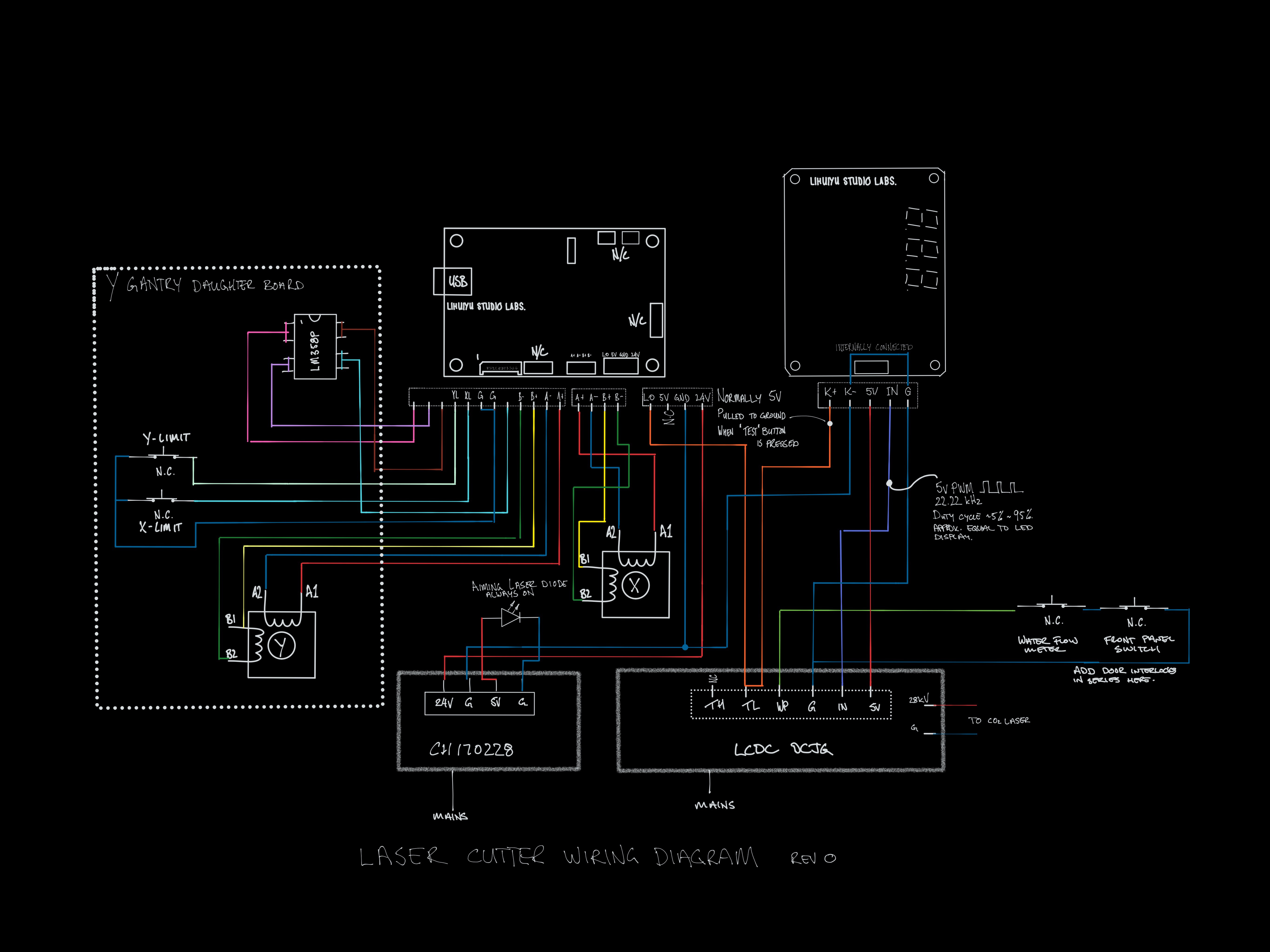
I have gone through the wiring and sketched it out. I also took out the laser power control board (the one with 888 on it) and pit it in a logic analyser. The IN pin sends a 22.22kHz PWM with a duty cycle that more or less matches what is shown on the display. The K- pin is pulled up to 5v normally and to ground when the test button is pressed.

Discussions
Become a Hackaday.io Member
Create an account to leave a comment. Already have an account? Log In.