 Xabi Z
The software tasks can be divided into the following parts:
- Setting up the audio: The USB Card needs to be set as the main card
- Reading the dialed numbers: The rotary-dial needs to be read and its pulses translated to the dialed number
- Reading if the hook is lifted: It was necessary to lift up the hook to start dialing a call. We want to replicate this behaviour. We also want to use the action of hooking down the receiver to end a call.
- Setting up a Bluetooth link to our smartphone: Ideally the tabletop-telephone needs to be detected as a Bluetooth hands-free set and the appropriate signals (start call, hang call, audio-link) have to be exchanged between the smartphone and the "dumb-phone".
Setting up the audio
The Raspberry Pi Zero with the latest Raspbian operating system should already automatically detect most of the USB sound-cards. To avoid any sort of confusion between devices we will disable the builtin audio by commenting the following line out from the /boot/config.txt file.
dtparam=audio=on
Afterwards we can already test the speaker by typing the following command:
speaker-test --test=wav -w /usr/share/sounds/alsa/Front_Center.wav
We should be able to hear "Front Center" repeatedly spoken from our receiver's speaker.
We will come back to the audio setup when configuring the Bluetooth. The services we are willing to use for the Bluetooth hands-free profile require Pulseaudio to be modified, compiled, and installed from source.
Detection of signals
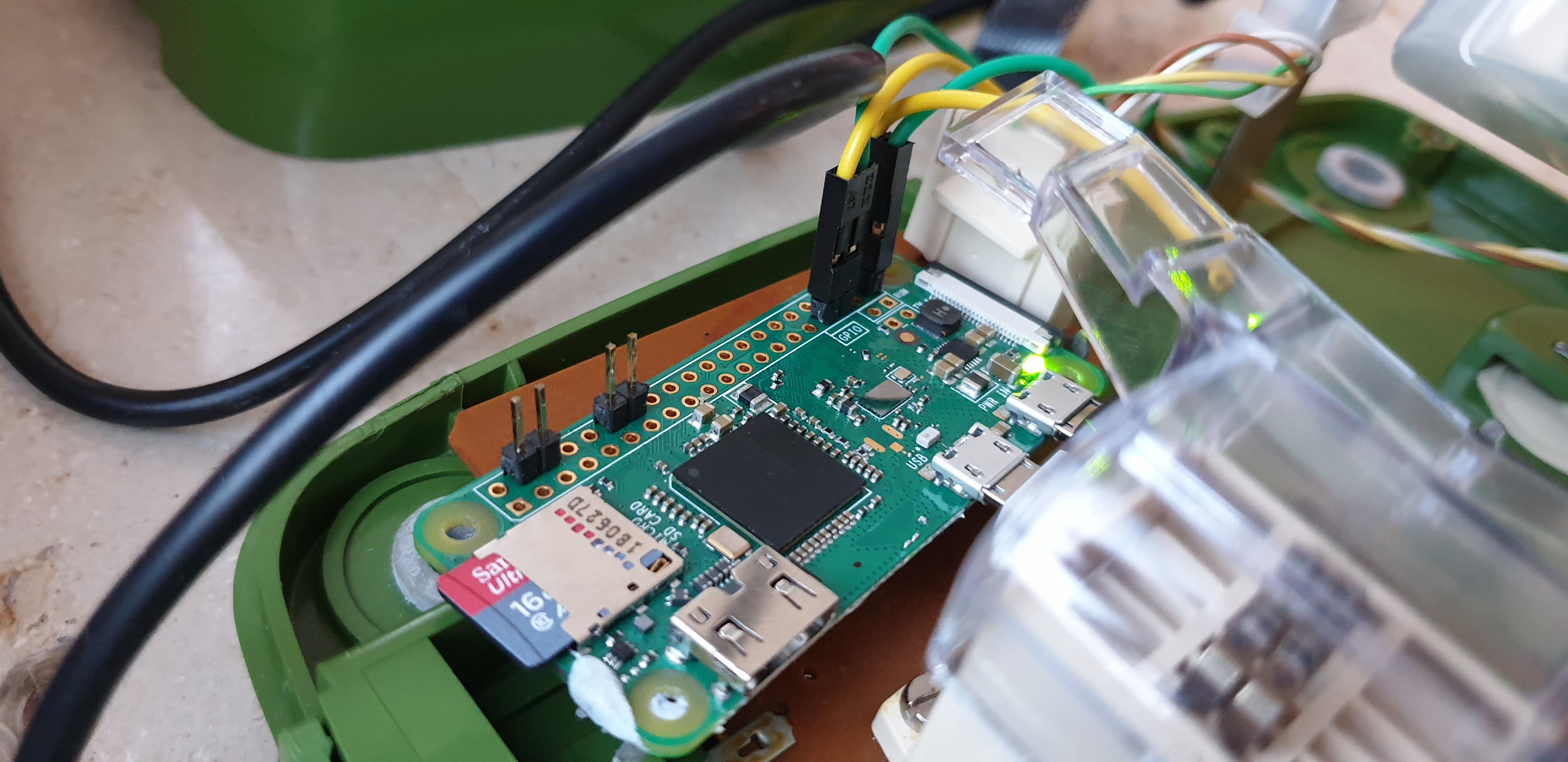
The dialing pulses and the hook can be read using the RPi.GPIO Python module. The following class snippet can be used to place the decoded number into a queue and be accessed from other threads (more about multi-threading and queuing can be read here).
class RotaryDial(Thread):
    def __init__(self, ns_pin, number_queue):
        Thread.__init__(self)
        self.pin = ns_pin
        self.number_q = number_queue
        GPIO.setup(self.pin, GPIO.IN, pull_up_down=GPIO.PUD_UP)
        self.value = 0
        self.pulse_threshold = 0.2
        self.finish = False
        GPIO.add_event_detect(ns_pin, GPIO.FALLING, callback=self.__increment, bouncetime=90)

    def __increment(self, pin_num):
        self.value += 1

    def run(self):
        while not self.finish:
            last_value = self.value
            time.sleep(self.pulse_threshold)
            if last_value != self.value:
                pass
            elif self.value != 0:
                if self.value == 10:
                    self.number_q.put(0)
                else:
                    self.number_q.put(self.value)
                self.value = 0
Similarly we can detect if the receiver is hooked or lifted:
# Receiver relevant functions
GPIO.setup(self.receiver_pin, GPIO.IN, pull_up_down=GPIO.PUD_UP)
    if GPIO.input(self.receiver_pin) is GPIO.HIGH:
        self.receiver_down = True
    else:
        self.receiver_down = False
GPIO.add_event_detect(self.receiver_pin, GPIO.BOTH, callback=self.receiver_changed, bouncetime=90)

def receiver_changed(self, pin_num):
    if self.receiver_down:
        self.receiver_down = False
    else:
        self.receiver_down = True
Notice that in my case because of wiring optimization I chose to join both switches to active low value (meaning they will be grounded when closed). Therefore the pull-up settings have to be set accordingly.
Discussions
Become a Hackaday.io Member
Create an account to leave a comment. Already have an account? Log In.
I had to edit
sudo nano /usr/share/alsa/alsa.conf
defaults.ctl.card 0
defaults.pcm.card 0
to
defaults.ctl.card 1
defaults.pcm.card 1
after i plugged in my usb audio device...
Are you sure? yes | no