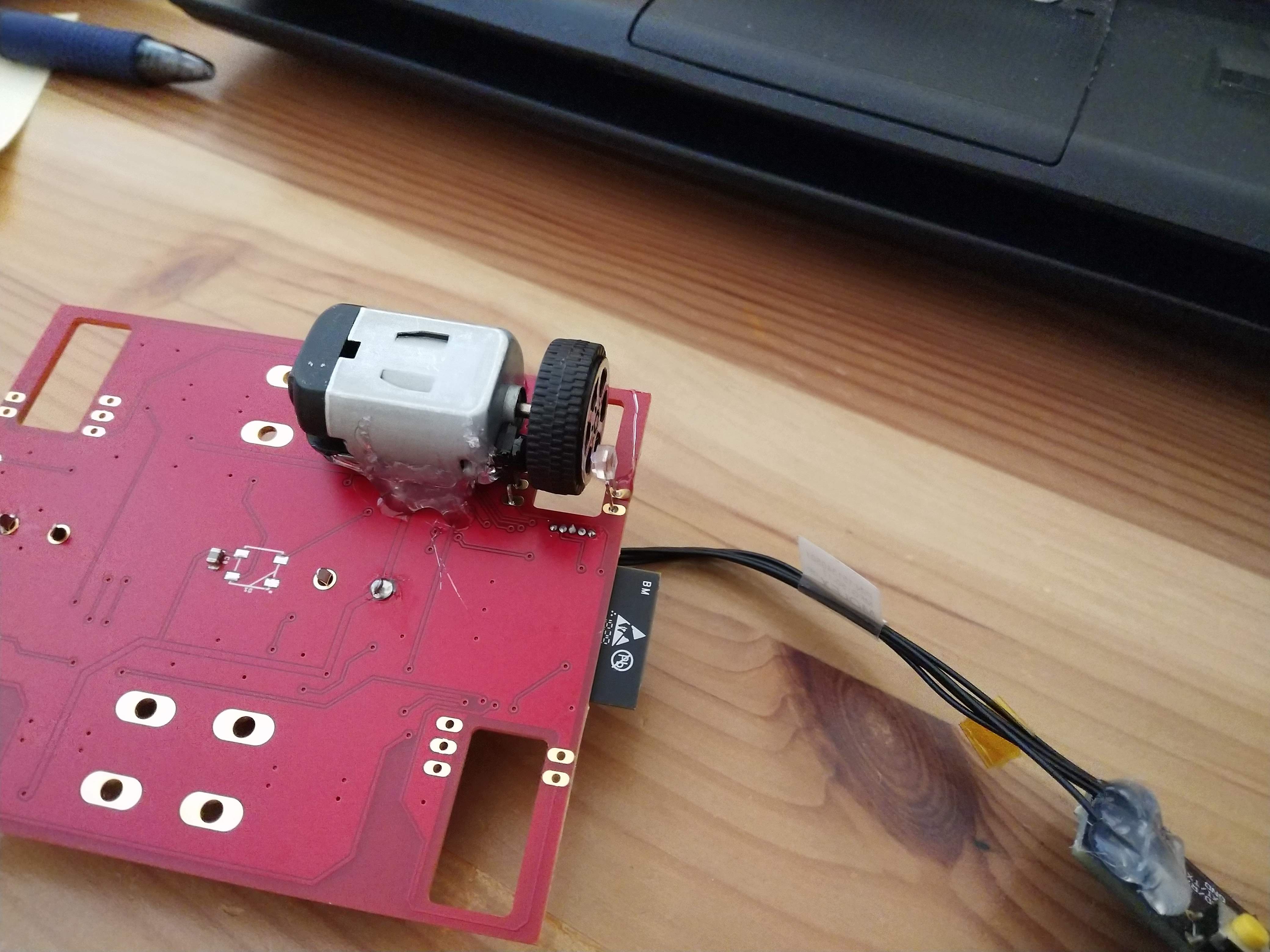
I built a second revision of the car, but ran immediately into a major design fault. The motor drivers are unable to run from a single cell battery, and therefore the system could not drive. However, I was able to test sections of it. This system is intended to have a lot of feedback for control purposes, but still be cheap. A MPU-6500 module is included for acceleration and rotation rate measurements. Each wheel has its own motor. The motor terminals connect directly to the PCB, and the motors are held with hot glue. Each motor is independently controlled, and I designed a DIY encoder using modulated IR transmitters and receivers. A side-look IR transmitter is modulated at 50% duty cycle at 56KHz, and a side-look IR receiver is mounted on the other side of the wheel and outputs a digital low signal whenever IR of the correct frequency is received. The wheel has 6 spokes. This setup cannot detect direction, but can detect speed. I tested this, and it is working quite well, although with the expected limited resolution.
The next version needs to fix the voltage issue, but this design will enable some interesting control:
- Torque vectoring control
- Traction control
- Closed loop rate control through turns
It would be fun to test an open-loop controlled system against one with advanced control to see how much it can speed up the system. Each motor is more than powerful enough and the hard plastic wheels have very little grip, so the system will be able to drift around.
Discussions
Become a Hackaday.io Member
Create an account to leave a comment. Already have an account? Log In.