The hardest part of this project is going to be picking the correct amplifier. I want to be able to measure currents accurately across a wide dynamic range. At the least, I want to be able to measure currents down to 5uA and up to 100mA, but a higher top end would be preferable. it might be necessary to use different amplifiers for difference ranges, but I would like to avoid that if possible.
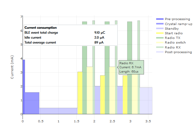
To give an idea of the types of currents that I want to be able to measure, here is a predicted current consumption estimate for the nRF52 preparing to send a bluetooth notification.

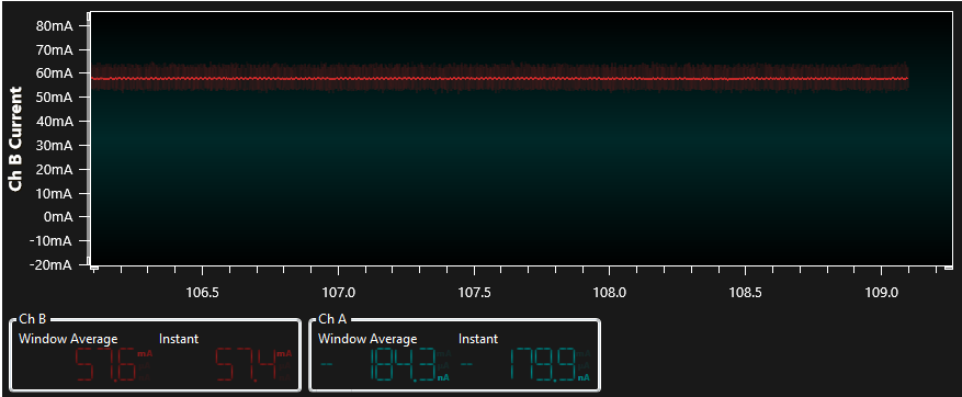
In contrast to the nrf52, which is optimized for low power operation, your typical arduino program will use ~50mA - even if it isn't doing anything. Here is a power sample from a very simple arduino program that is just polling a magnetometer and feeding the data out to a serial port.
My first inclination was to use a current sense amplifier (sometimes called current monitors). As the name implies, the are specialized instrumentation amplifiers designed specifically for measuring high-side currents (measured above the system load) developed across shunt resistors. The cool thing about current sense amplifiers is that they can measure common mode voltages that exceed their supply voltages. This means that you can have amplifiers like the TSC101 that can measure common mode voltages ranging from 2.8V to 30V even when supplied by only 4V. This dark magic allows you to put your sense resistor above your load instead of putting it down next to ground.
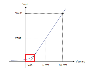
The problem with current sense amplifiers is that they have huge dead-zones at low input voltages. For example, check out this plot from the TSC101 datasheet.
 The voltage listed here as Vsense is the differential voltage measured across the shunt resistor. Between 5mV and 50mV it looks awesome, but the lower the voltage gets the more uncertain the measurement becomes. This error is the result of the amplifier offset voltage. The higher the offset voltage, the worse the amplifier will be at measuring low currents. This particular amplifier has a nominal offset voltage (labeled Vos in the figure) of 0.2mV at a temperature of 25degC.
That means that if I were to use a 50mOhm shunt resistor, at a current of 5uA, the the sense voltage would be 250nV. The offset voltage is 200000nV, so there is no way that we would be able to measure the current accurately. I could (and probably will) use a larger shunt resistor, but even if I were to use a 1 Ohm resistor, the sense voltage would be 195uV less than the offset voltage for this particular amp. The takeaway here is the the offset voltage is very important.
Time to picks an amplifier. Here are some of the options I considered.
| Device | Vos | Bw (3db) | Gains | cost | complexity |
| TSC101 | 200µV | 500kHz | 20,50,100 | $.76 | very low |
| MCP6C02 | 1.9µV | 500kHz | 20,50,100 | $1.28 | low |
| INA233 | 10µV | * | ? | $1.5 | high |
| MAX9923t | 0.2µV | 50kHz | 25,100,250 | $2.01 | low |
| NCS210RSQT2G | .55µV | 40kHz | 200 | $.36 | low |
* the ina233 has an integrated ADC, so the bandwidth doesn't matter. How fast is the sampling rate? Well, it only has an i2c interface, so probably not that fast.
** cost is per thousand.
Annoyingly, the best looking amplifier is also the most expensive one. The NCS210RSQT2G looks pretty good and the price is appealing, but the variance on Vos is much higher than the maxim amp. I might look into the cheap alternative in the future, but for now I think I have to go with the maxim amplifier.
Discussions
Become a Hackaday.io Member
Create an account to leave a comment. Already have an account? Log In.