 Lutetium
 I'm sure you have some you could share as well
 how much calibration sucks really depends on your production volume and how willing you are to invest the time & money to make it not suck
> I'm working on a DIY CO detector using a sensor like this:
That's a great idea @Alex Ryker! What does the circuit look like?
like are you pulling off a manufactured sensor...or are you creating the sensing element from scratch?
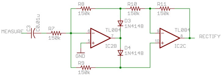
> I'm working on a "precision rectifier" circuit also known as a "super diode". A diode and op amp (to be sampled by an ADC).
Another good looking project @Will Patton. Any circuit you can share here?
> how much calibration sucks really depends on your production volume and how willing you are to invest the time & money to make it not suck
As the Teensy creator would surely know :-D Lots of volume there!
How much calibration is there for your designs @Paul Stoffregen ?
fwiw, I'm working right now with a relatively new "smart amplifier" chip, which requires a calibration of the speaker
ahh, yeah
so you're characterizing and then storing the variables in an EEPROM or something?
 I'm trying to do as much from scratch as possible--more fun that way :)
I don't have much drawn out yet, but I've cleared my schedule this Saturday to change that. I'll probably make a Hackaday.io project out of it once it's a little more substantial.
 >I'm sure you have some you could share as well
Honestly, I haven't worked with much in the way of analog for a while; I've mostly been in battery and power systems, and more generalized high volume. I'm definitely always curious about everyone else's tricks. =)
a lot of the gas sensors have some kind of chemical element and then the output needs to be amplified somehow. So that's a good project, but there can be a lot of variability
 i've got some photodiodes with bandpass filters on, that i'm trying to find the best way to measure the light at a certain wavelength, i presume i'd need to use an op-amp like in your diagram, to convert the current to voltage? but it seems there's different modes to use a photodiode, which confuses me somewhat (the photodiodes monitor two different wavelengths, trying to measure a peak/trough of a liquid for a type of spectroscopy)
> i've got some photodiodes with bandpass filters on
Passband of light or of the electrical signal?
For Teensy, there's really no calibration at all during testing. The chip's ADC does have a self calibration that's done at startup, which appears to just null out DC offsets
passband of light sorry
Good to know! What I've been thinking about most recently is powering the thing--ideally I'd like it to look like a lot of COTS CO detectors and have an integrated AC plug. However, I'm not quite sure how best to go about that--safety and potential noise are concerns I've had. Any thoughts on that?
> i'm trying to find the best way to measure the light at a certain wavelength, i presume i'd need to use an op-amp like in your diagram, to convert the current to voltage?
Yeah, you'd want to convert it. It's tough because photodiodes effectively combine all of the wavelengths they absorb
> However, I'm not quite sure how best to go about that--safety and potential noise are concerns I've had. Any thoughts on that?
Out of my pay grade (outside the scope of this chat, but a good subject)
For a couple products I made on a consulting basis (back in the days when Teensy was just getting started....) I used quite a lot of calibration. I even still have an Agilent 34410A on the workbench - which was used for a of that old work
> The chip's ADC does have a self calibration that's done at startup, which appears to just null out DC offsets
The best way to do it
I think a lot of sensors are piping out digital signals these days
so it's getting less common to have to deal with analog signals for some things
there are a bunch of off the shelf chips that are "analog front ends" that take care of a lot of things
One of those old products had an AVR chip, with signals coupled to its ADCs, and a 2% (but highly stable) reference chip.
the signals went through resistor dividers which used resistors in those little 4-resistor arrays (1206 size SMT), so the resistors needing ratios were on the same physical package to track with temperature, but the tolerance wasn't good at all
yeah, those kinds of problems can be stinkers
that's trading the time cost of calibration for the cost of stable parts
if you can get the calibration to be consistent over time
then that's great
pretty easy to solve with calibration - which is why I have that 6.5 digit bench multimeter ;)
but usually the good parts at the beginning (0.1% accurate) are also the ones with low drift
which brings up another good point
learning how to add up all of the errors in your circuit are important
having an "OK" resistor at the beginning of your signal chain might not seem to be a problem
but if you have a 10x gain stage and another 10x gain stage after that
that small error really adds up
so you need to look at the block diagram and see how errors in your circuit might compound.
one of the thorny problems I usually hit with calibration is getting close timing match between the device under test and the reference (like that 6.5 digit DMM)

that's great, @Will Patton
Chris, you asked:
Here is an image from Stack Exchange (SE).
and is this for low level AC measurement?
especially if the "signal" is measuring AC power. Even tiny fluctuations in the AC waveform wreck havoc on the quality of the cal if the timing isn't very closely aligned between the device under test (like that AVR chip) and the reference
Precision Rectifier: Yes, I would say "small signal" - a range from 5mV to 1.4Vp-p. The trick is AC and DC coupled versions of the circuit.
so we're winding down here I think?
I'll put a few resources in the chat
Excellent Chris - you're the best!
I usually refer people to the EEVblog videos on op amps, I htink Dave did a good job with that stuff
vintage EEVblog, that is
haha
https://www.youtube.com/watch?v=Y0jkPLuFdnM
https://www.youtube.com/watch?v=7FYHt5XviKc
as for books, Art of Electronics is ok
but it's dense
![]() Thanks Chris for your time
Thanks Chris for your time
 flourless chocolate torte of electronics books
 OK, that was a neck-snappingly fast hour with Chris. Great stuff! I want to give Chris the opportunity to bow out if he needs to, but feel free to stick around and keep answering questions if you want to - don't think we'll run out any time soon. I'll just say an official thanks to Chris for a lively discussion and for spending time with us here on the Hack Chat.
Don't forget that next week we'll be talking to Josh Lifton from Crowd Supply and crowdfunding your projects - https://hackaday.io/event/165483-crowd-supply-hack-chat-with-josh-lifton
once you're past art of electronics, I Like "Design with Operational Amplifiers and Analog Integrated Circuits" by Sergio Franco
https://www.amazon.com/Design-Operational-Amplifiers-Integrated-Circuits/dp/0072320842
%2c445%2c291%2c400%2c400%2carial%2c12%2c4%2c0%2c0%2c5_SCLZZZZZZZ_.jpg)
Design with Operational Amplifiers and Analog Integrated Circuits
Franco's "Design with Operational Amplifiers and Analog Integrated Circuits, 3e" is intended for a design-oriented course in applications with operational amplifiers and analog ICs. It also serves as a comprehensive reference for practicing engineers. This new edition includes enhanced pedagogy (...
And I'' be posting a transcript in case anyone missed anything. I know I did...
Watch YouTube! Better than a book! ;-)
Also shout out to the folks that taught me a lot of this stuff
Keithley (now Tek) have a good book on measurements and signals called the Low Level Measurement Handbook (now in its 7th edition) https://download.tek.com/document/LowLevelHandbook_7Ed.pdf
past that, read app notes and datasheets like it's your job
There was an old blogspot blog that followed along as the author read Jim Williams: http://readingjimwilliams.blogspot.com/p/best-app-notes.html
One book rec I'd love to add to the list: The Circuit Designer’s Companion
that's Kent Lundberg (@doctoranalog on twitter)
yeah, that one is ok as well. I recommend not getting the kindle verison
Oh the stuff by Hank Zumbahlen is also great, the Linear Circuit handbook
https://www.analog.com/en/education/education-library/linear-circuit-design-handbook.html

Linear Circuit Design Handbook, 2008 | Education | Analog Devices
Linear Circuit Design Handbook, Edited by Hank Zumbahlen, Published by Newnes/Elsevier, 2008, ISBN-978-0-7506-8703-4 (Also published as Basic Linear Design, Analog Devices, 2007, ISBN-0-916550-28-1).Fundamentals and applications of data acquisition components. Contains much of the material covered in Data Conversion Handbook and Op Amp Applications
I remember I found those PDFs bit by bit
thinking I was finding illegal copie
s
nope, free book by ADI
haha
I also interviewed Hank on The Amp Hour (my podcast with Dave Jones), he was great: https://theamphour.com/185-an-interview-with-hank-zumbahlen-zoppa-zumbahlen-zateticism/
Other analog folks I've interviewed:
![]() if there's still time for a quick question - when you're designing analog stuff like this, do you jump straight into hardcore math or are you throwing up something that's like "this should more or less work" and then refining from there?
if there's still time for a quick question - when you're designing analog stuff like this, do you jump straight into hardcore math or are you throwing up something that's like "this should more or less work" and then refining from there?
 Link to transcript: https://hackaday.io/event/165370-low-level-analog-measurement-hack-chat/log/165830-hack-chat-transcript-part-1
![]() and if it's math, do you have a recommendation of how to get better at that?
and if it's math, do you have a recommendation of how to get better at that?
https://theamphour.com/the-amp-hour-119-luculent-linear-legacy/
https://theamphour.com/the-amp-hour-77-winsome-waveform-wizardry/
https://theamphour.com/the-amp-hour-109-hexagram-hardware-holism/
https://theamphour.com/196-an-interview-with-mike-engelhardt-spice-simulator-synteresis/
https://theamphour.com/340-an-interview-with-jason-cerundolo/
https://theamphour.com/348-an-interview-with-art-kay/
https://theamphour.com/392-an-interview-with-matt-duff/
> if there's still time for a quick question - when you're designing analog stuff like this, do you jump straight into hardcore math or are you throwing up something that's like "this should more or less work" and then refining from there?
Honestly I'm normally copying an app note at the beginning. Borrowing knowledge from others at first and then really udnerstanding it when I'm hands on at the bench (or when things go wrong)
starting from first principles and math is a good way to not get any circuits out into the world
but it's important to understand over time, IMO
as for how to get better at it, I've done it by putting myself into a situation where i need to understand it, that's the best motivator
which I realize isn't that helpful of an answer
![]() nope it's very helpful. thank you!
nope it's very helpful. thank you!
OK, that's all from me, off to troubleshoot a circuit!
thanks for stopping by to see my rambling!
Discussions
Become a Hackaday.io Member
Create an account to leave a comment. Already have an account? Log In.