2017 is here !
I haven't kept up with the latest logs, shame on me, but there is a bit of progression.
Now, we embark on a 3-months period (10 workshops) where we are asked to design and build a project.
- it must be participative and inclusive so kids and others can come and go easily without breaking the project
- it must be easy but not too trivial.
- it must be useful, add something to the workshop's room for example
- from there, it must be modular, made of many identical pieces
We have brainstormed and chosen the following project :
make many modules, each module writes a letter with 14 segments made of LEDs, modules can be chained to create words
The letter is selected either with DIP switches or an external digital control (hooked to a Pi for example). This dual-mode ensures that no programming is required for testing the board or making the first applications. Later, when digital control and programming are understood, the boards will be easy to chain and create scrolling boards !
So the first workshop started with a brainstorm session that led to this outline, but is it possible and realistic ? We spent the rest of the workshop examining some of the salient aspects.
First, the PCB should be bound to the 10×10cm cheap PCB (made by dangerousprototypes and others). So a letter is approx. 10cm high and 7cm wide.
From there, we determined that there would be about 92 LEDs per letter ! There are 10 long segments of 6 LEDs and 4 (6?) segments of 4 LEDs. If we build 50 letters, that's almost 5000 LEDs to solder !
Another consideration comes from the requirement to run the circuit with digital inputs : the letters are powered from 5V. This creates a number of consequences for the circuit's organisation.
The segments having either 4 or 6 LED in series, under 5V, it seems appropriate to use LEDs in pairs, to make 2 or 3 parallel strings per segment, with a current-limiting resistor.
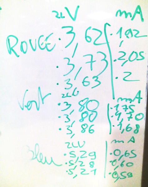
We did a few experiments with the LEDs we had lying around. Several colors (red, green and blue) were tested for electrical and visual properties.
A 1K resistor and two LED are wired in series then powered with a couple of CR2032 batteries (6V).

- The blue LED draw little current (0.6mA only) but require a significant voltage (2.75V) which makes it hard to use 5V. Without resistor, there is probably too much visual variations, and the available 5V/2LED=2.5V (give or take 10% due to possible wire attenuation) is not enough for a visible dot.
- The green LED are a bit faint, compared to others, and draw more current (1.9V@1.7mA). I noticed that the CR2032's voltage dropped significantly, unlike the other tested colors.
- We selected the red LED because they are visible yet don't draw much power (1.85V@2mA).
Tomorrow, we'll test which type/model of LED is best suited, from my personal stock...
Control : the segments are driven either by a DIP Switch or a 74HC circuit. The 74HC circuit is disabled when the DIPswitch is active, with the "output enable" pin.
The boards are chained so they have an input and output bus.
The original idea was to have a couple of 74HC574 to latch 16 bits but the wide bus was too cumbersome.
I have enough 74HC595 to replace this, so a serial / SPI interface will be used.
It's interesting because we'll learn about the shift registers...
 Yann Guidon / YGDES
Discussions
Become a Hackaday.io Member
Create an account to leave a comment. Already have an account? Log In.
cool idea, use students to do tedious manual labor, soldering 5000 LEDs ;)
Are you sure? yes | no
They're not even students. With 13-years olds, expect 10 to 20% defect rate and uneven aspects. But it's a good "introduction" to the kinds of crazy projects that seem to delight people : the more LEDs, the happier... And it's the right place to introduce the notions of "quality control" and let them understand the power of multiplications : it's from the beginning of a project that you can decide if you'll suffer the hell of endless labor.
OTOH if you're smart and can look further than your nose, you can "design for manufacturability" :-)
And I admit that certain kids come just for the pleasure of soldering stuff.
Are you sure? yes | no