To start with, here's the second stream for this project:
On the stream, I finished up the schematics and assigned all the footprints and 3d models.
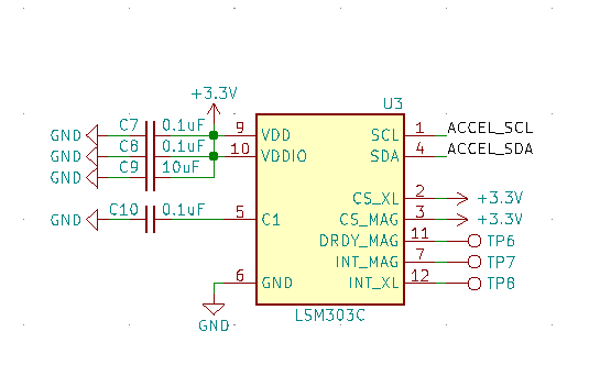
I also added the LSM303C accel/magnetometer sensor, just cause I think it might be fun to use with this board, if not needed, can always skip it during assembly.
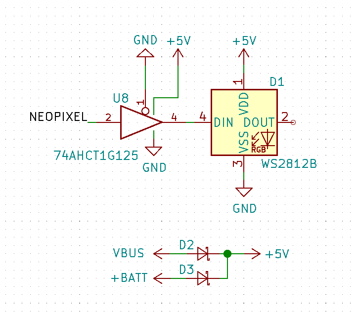
Next addition is a single Neopixel with a 5V supply:
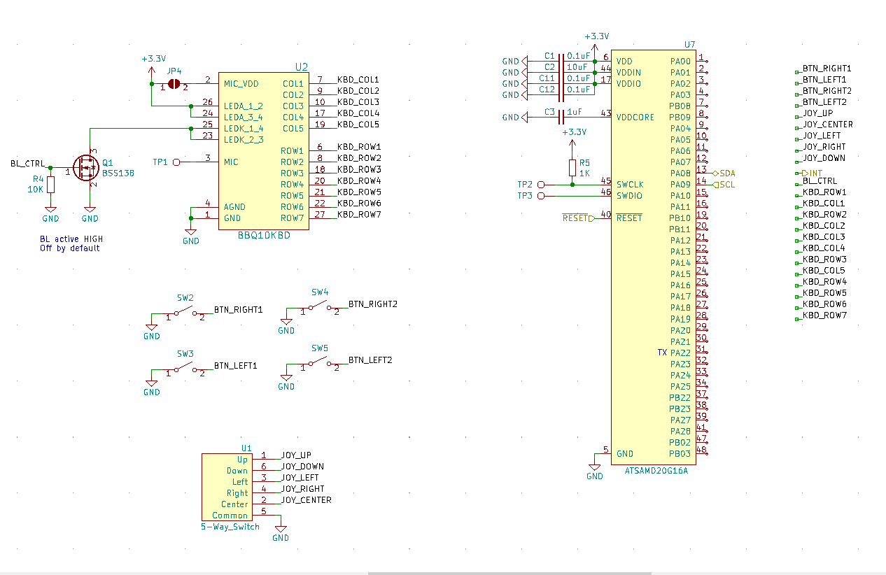
The last thing I did in the schematic was to change the ATSAMD20E used for the keyboard -> I2C stuff to an ATSAMD20G, which offers 12 more GPIOs, even though we only needed 2 more for the extra 2 buttons. The larger version is only 1 (one!) cent more, so it was a no brainer :)
Now onto the PCB.
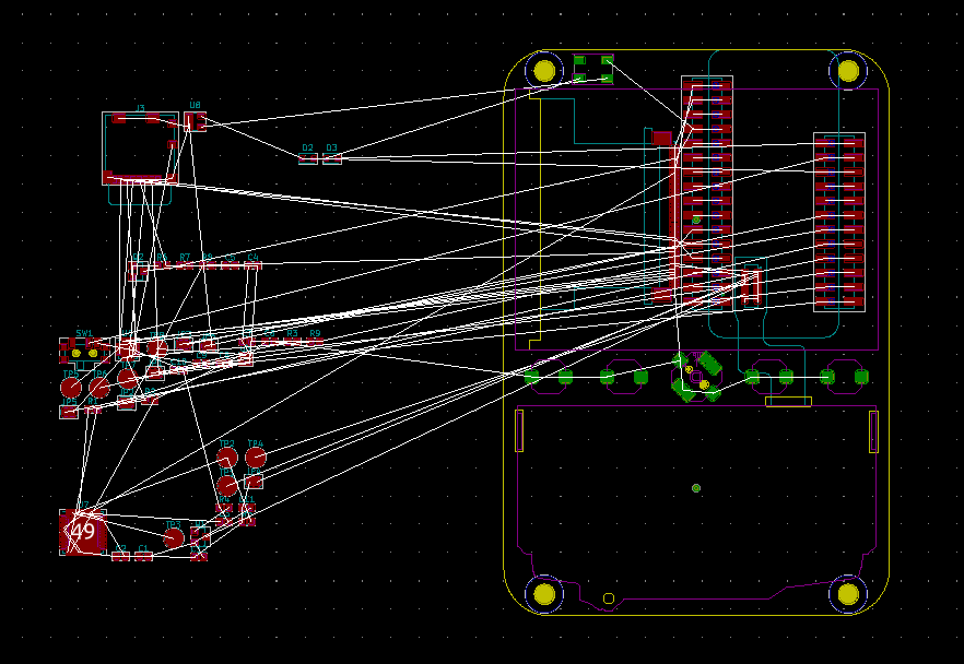
A lot of the work here was to simply copy and import the outline, footprints, and models from my previous project, so that part went quite fast. I laid out the 2 additional buttons, for a total of 4, I think the 2 extra ones will be quite useful!
The placement of many components is kind of limited, things like LCD, keyboard, joystick, and the buttons can only really go in one place, so I started with those. I also put the Neopixel in the top right corner up front, to get that older phone feeling.
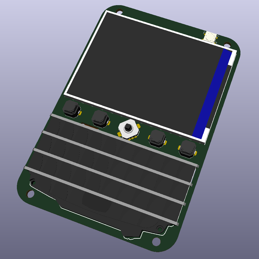
Now the tricky part is where the Feather should go, there are a few factors to consider here:
- USB location
- Battery connector accessibility
- Battery placement
- What your fingers touch on the backside when you're typing
- Weight distribution, battery on the bottom makes it more comfortable to hold.
I couldn't quite decide where it should be placed, so I took screenshots of all the options and started a poll on Twitter, check it out here, make your voice heard: https://twitter.com/arturo182/status/1128054190352273408
You can see all the 4 options in the tweet above as well.
Let me know what you think!
 arturo182
Discussions
Become a Hackaday.io Member
Create an account to leave a comment. Already have an account? Log In.