Specifications (as pictured)
- Input voltage: 11-16 volts DC
- Operating temperature: -20C - +40C
- Maximum continuous input current: 45 amps
- Idle current: 420mA
- Output voltage: 100-120 volts AC RMS (110V AC RMS nominal)
- Output frequency: 60Hz, +/- 0.5Hz
- Maximum output power: 400 VA
- Continuous output power: 350 VA
- Total Harmonic Distortion (THD): <5%
- Efficiency: 81%
- Galvanic isolation between DC input & AC output
- Protections:
- 60A input fuse
- Input under/over voltage
- Over-current / short
- Overload
- Overheat
- Dimensions: L=203mm (8"), W=144mm (5.7"), H=68mm (2.67")
- Weight: ~ 1.36kg (3lbs)
This project is done. If you do build it please read thru all the instructions first. I recommend that you build from the input section forward: power -> start -> controller -> inverter -> transformer & supplies -> sine.
CAUTION: high voltages, currents, and temperatures exist in this design.
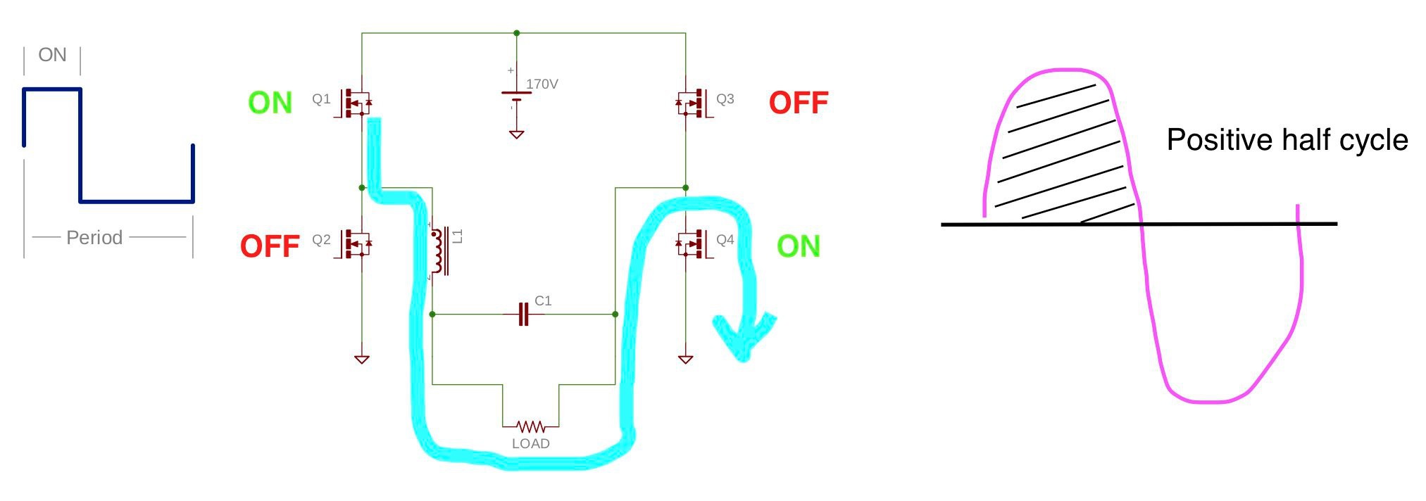
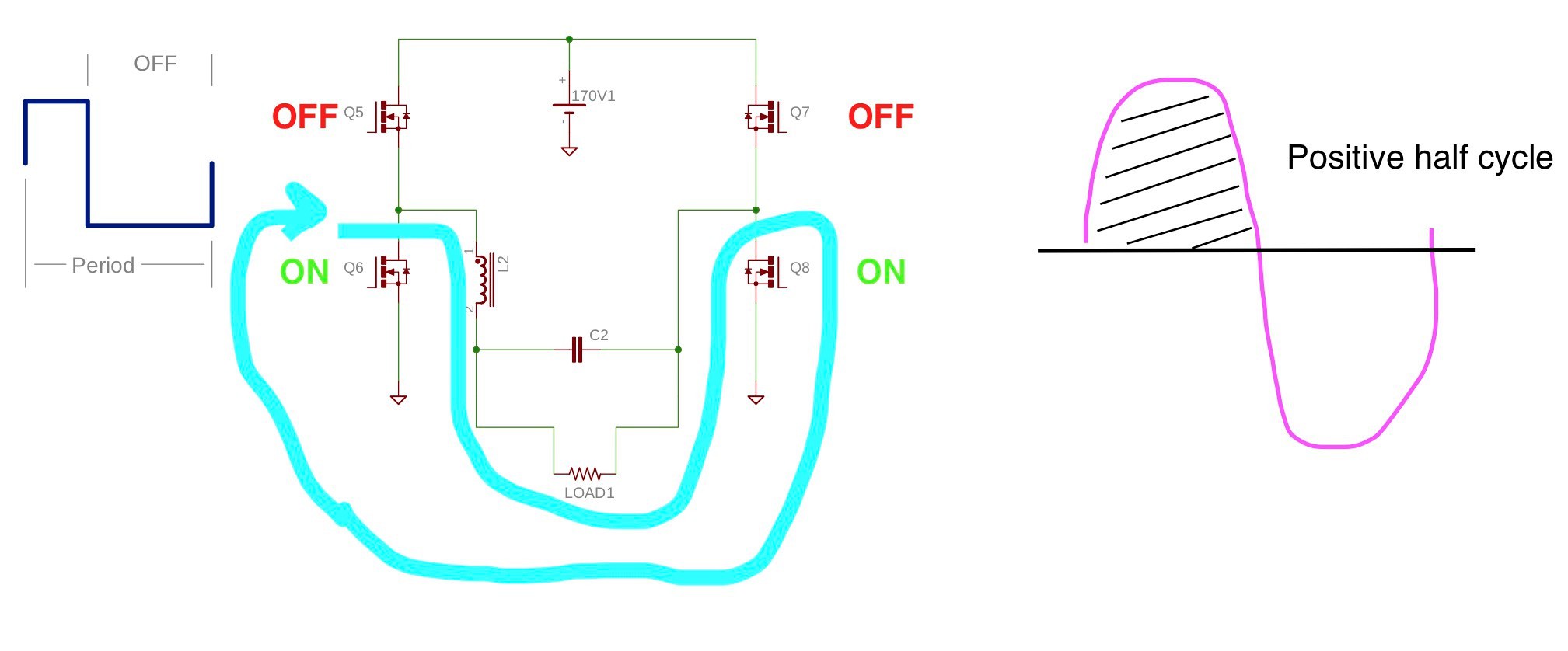
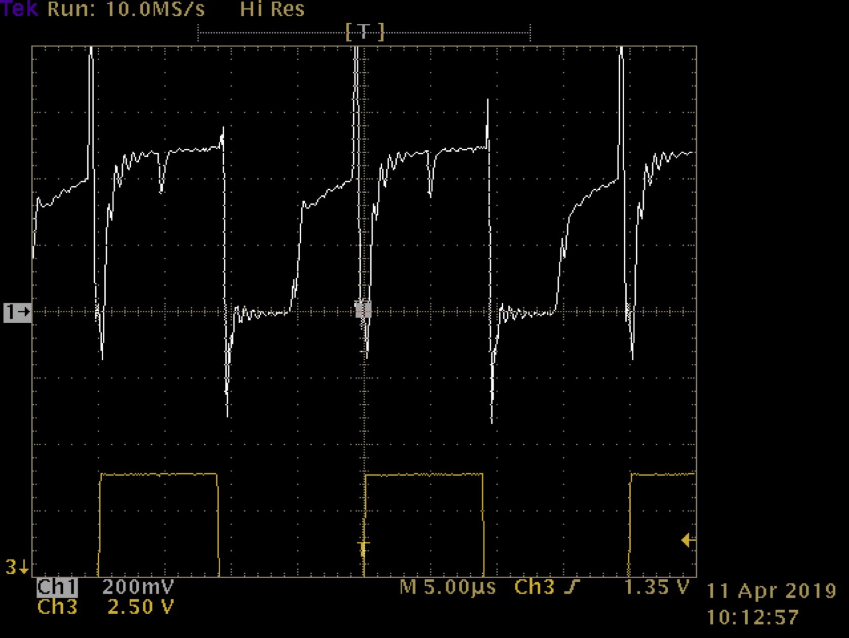
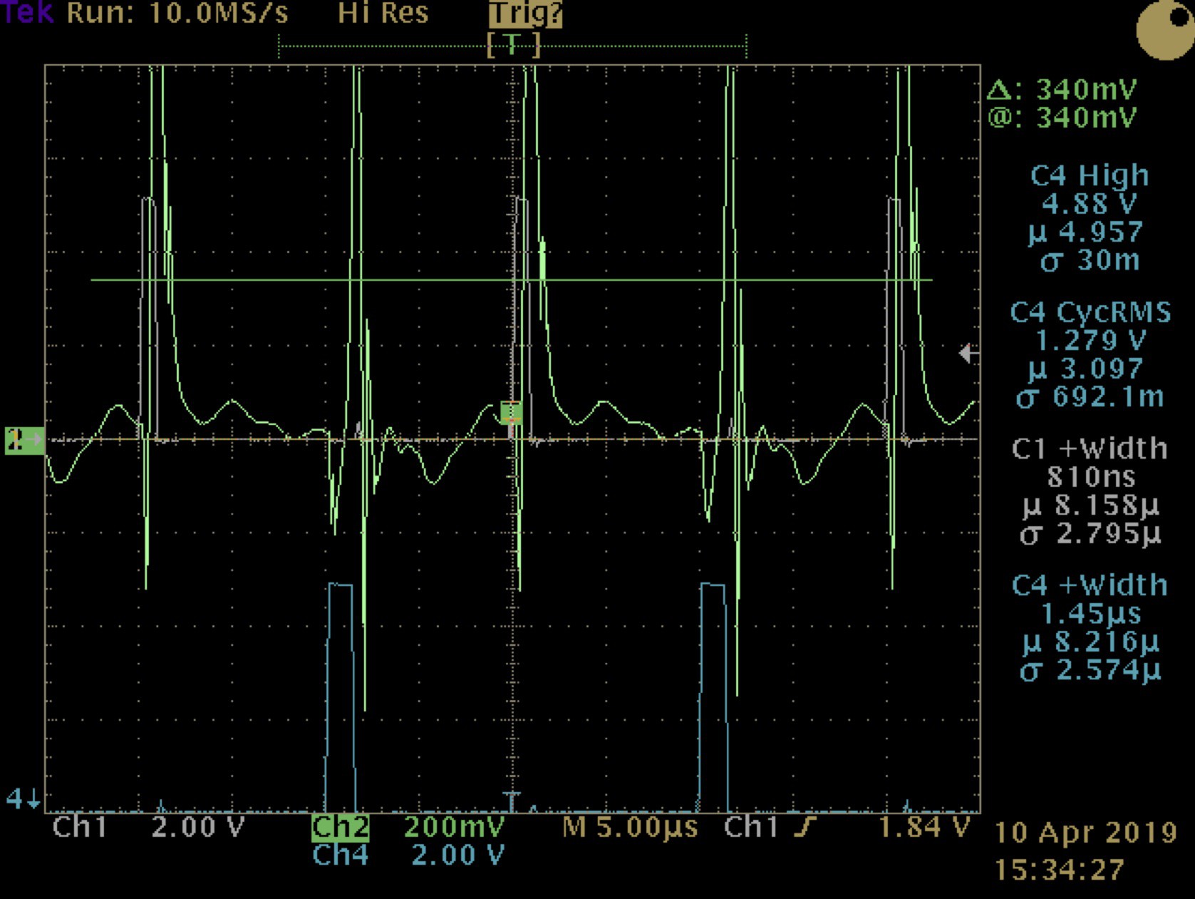
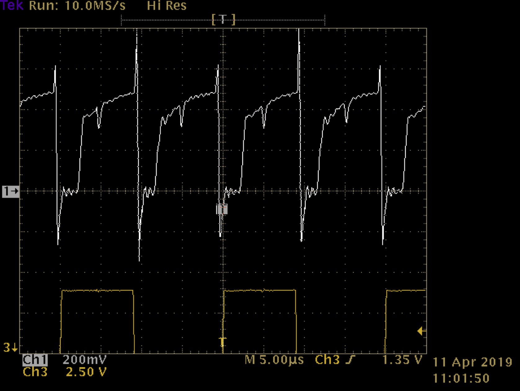
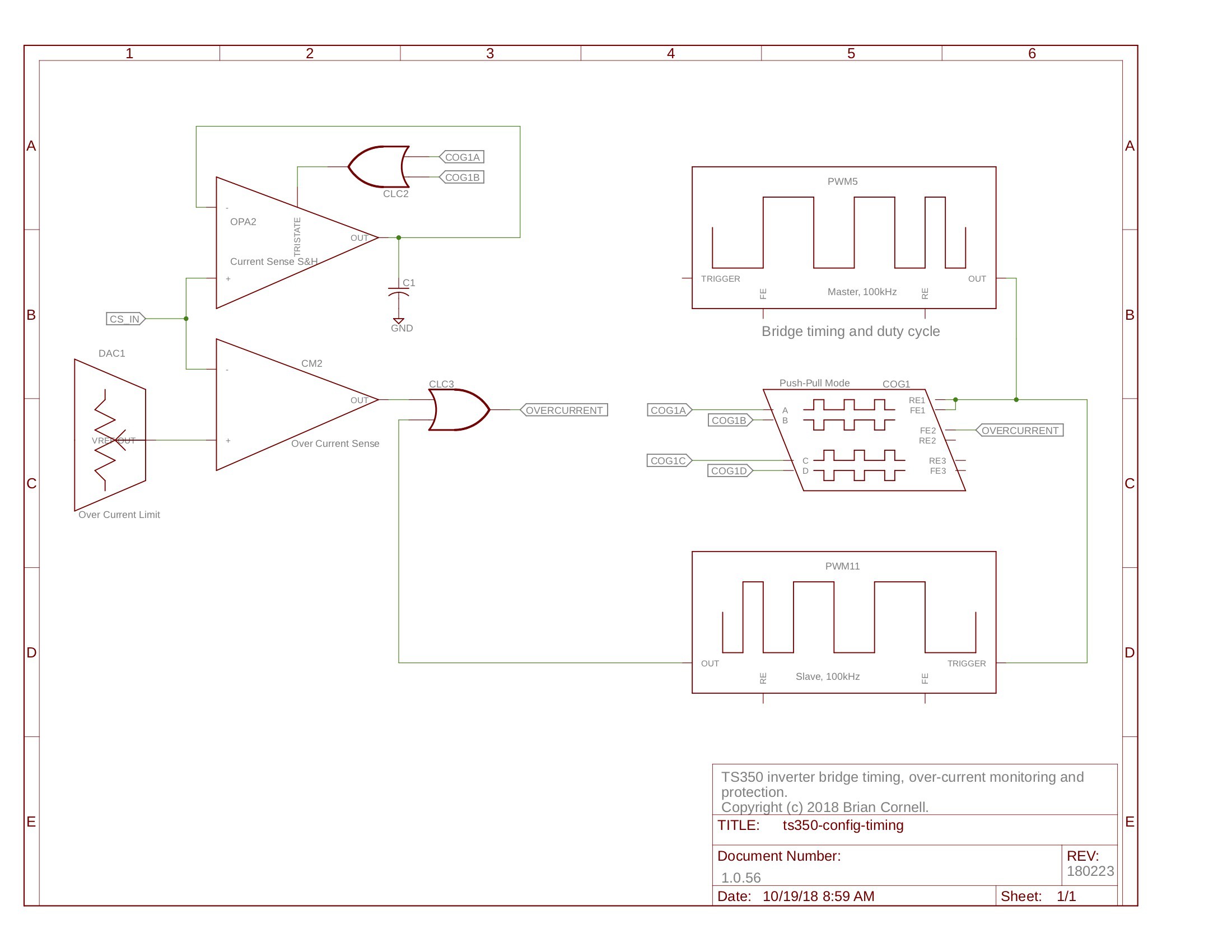
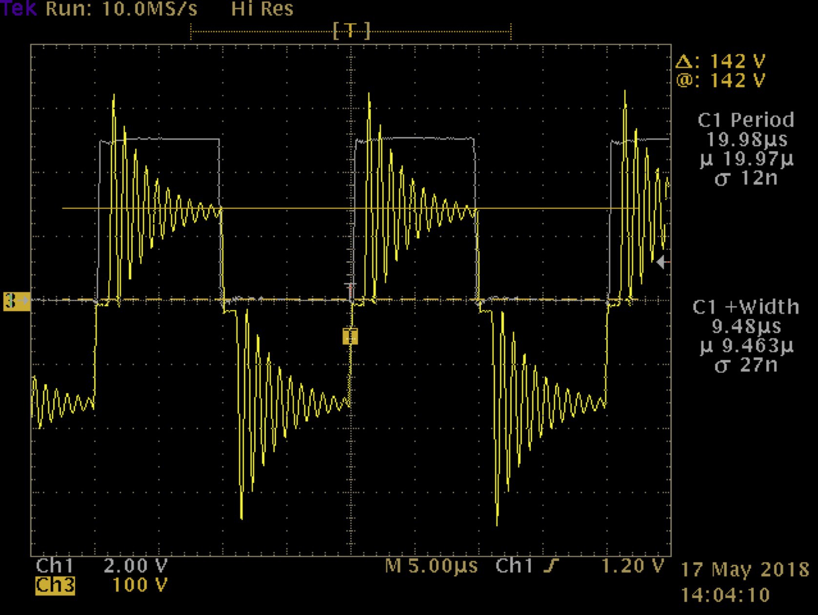
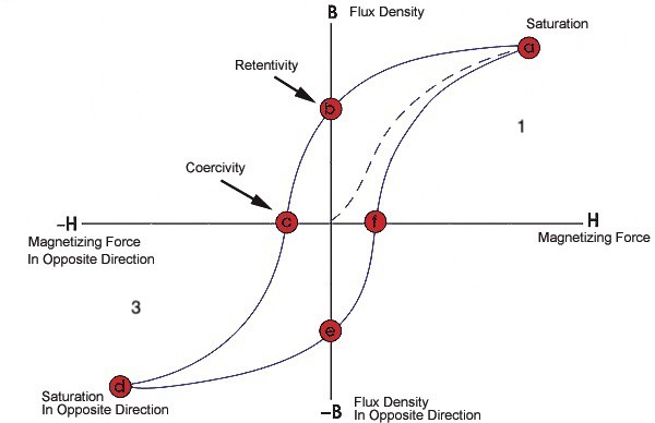
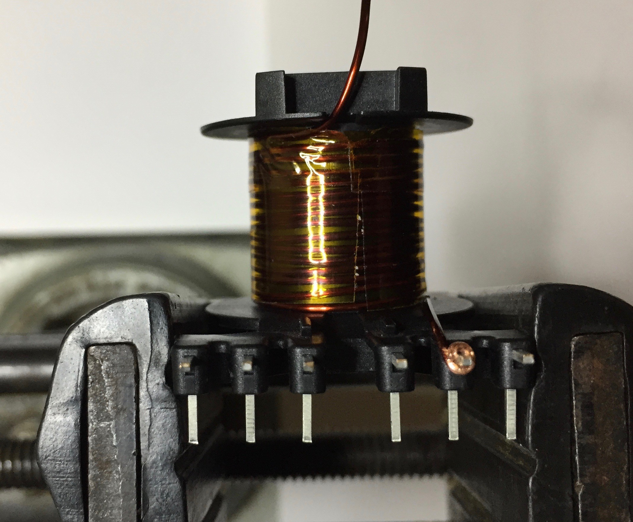
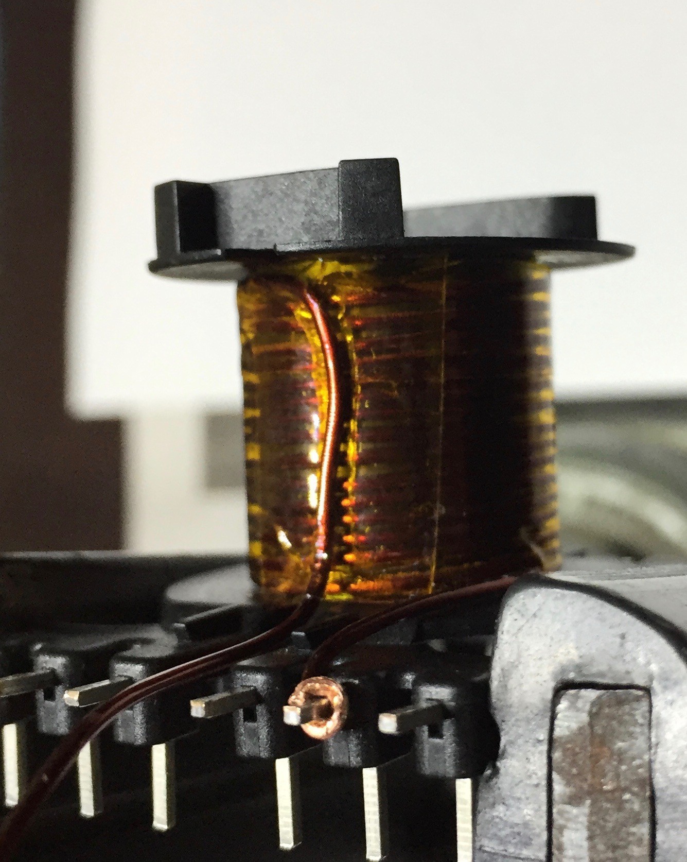
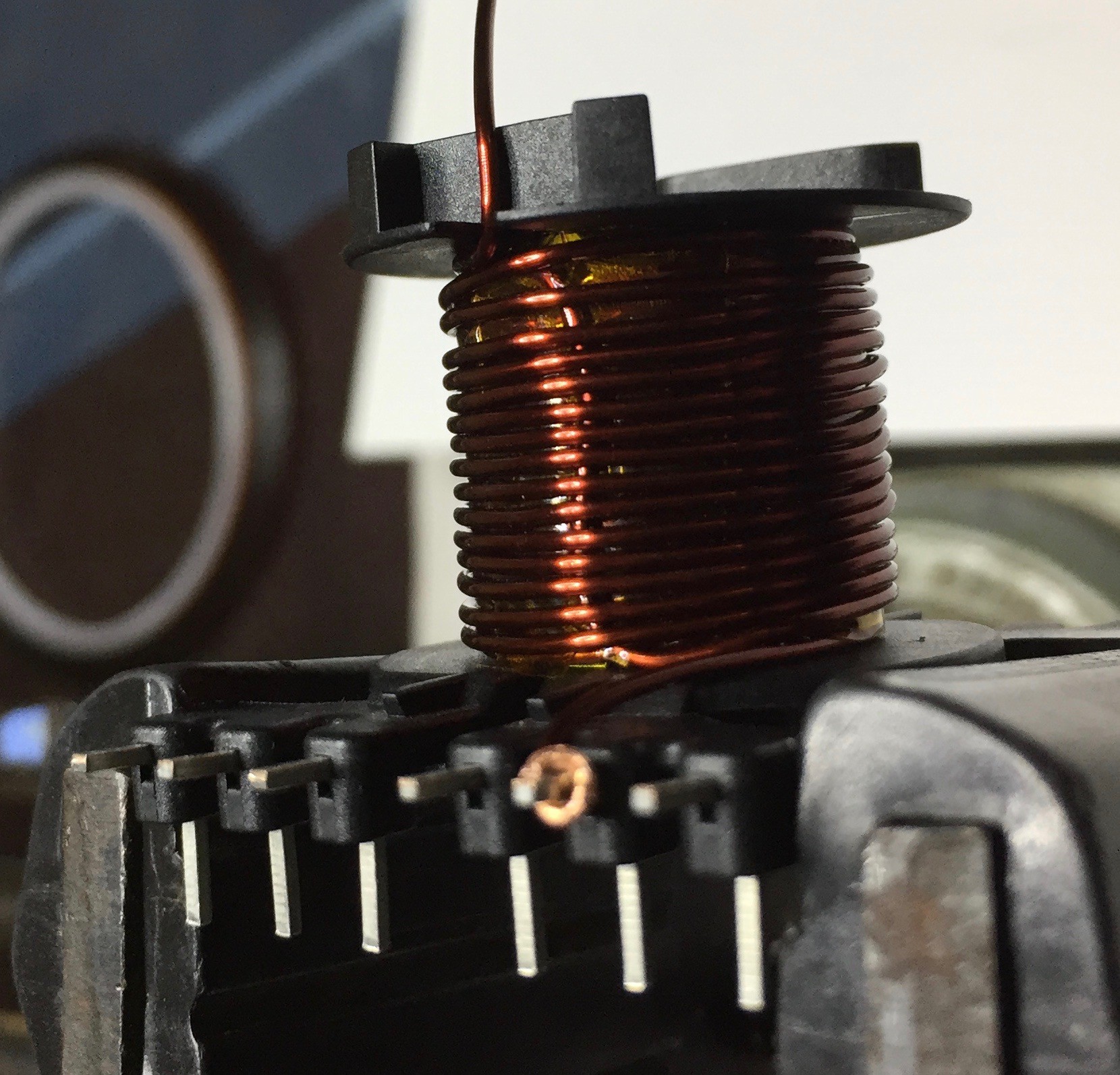

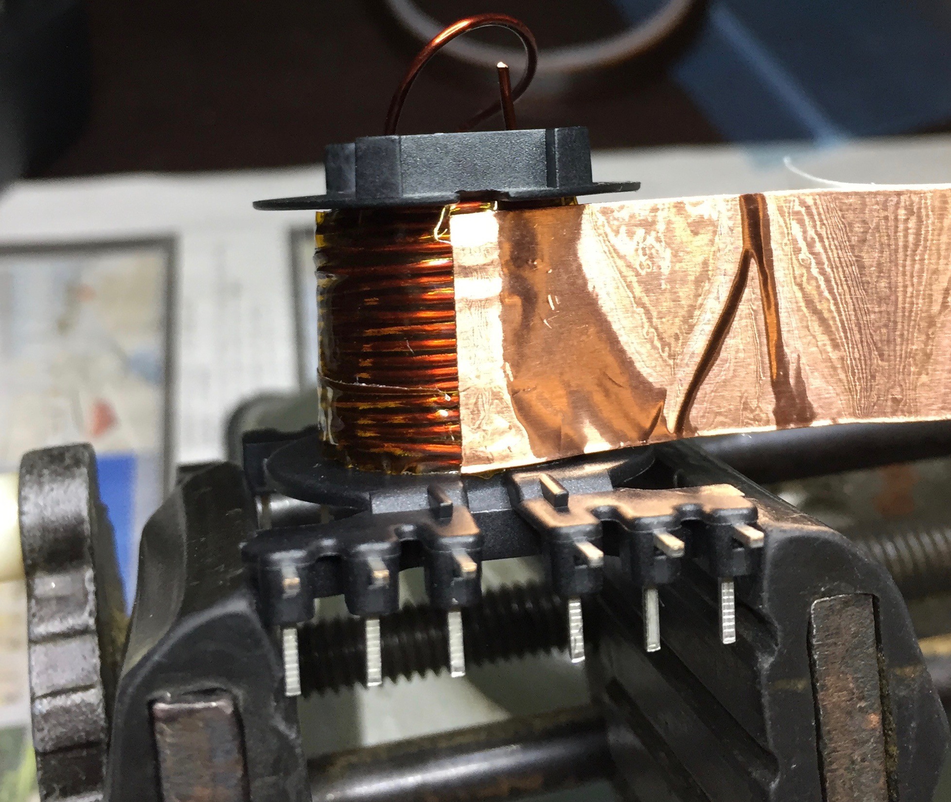

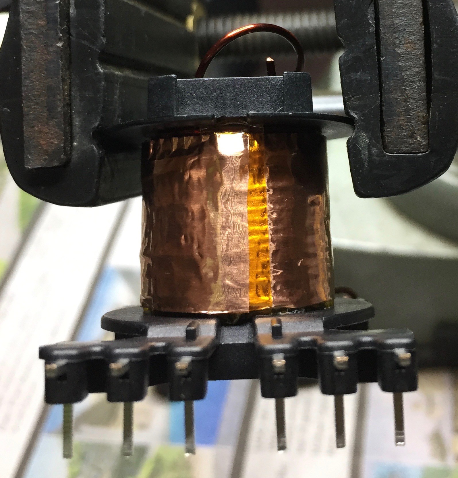
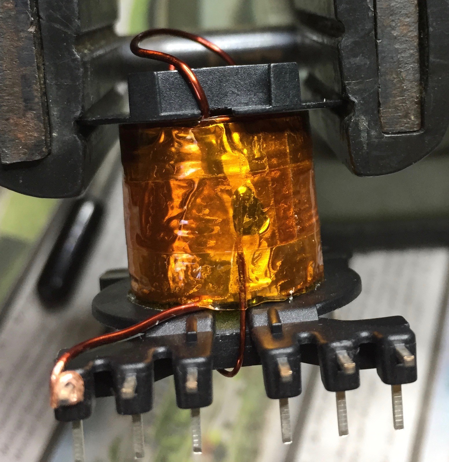
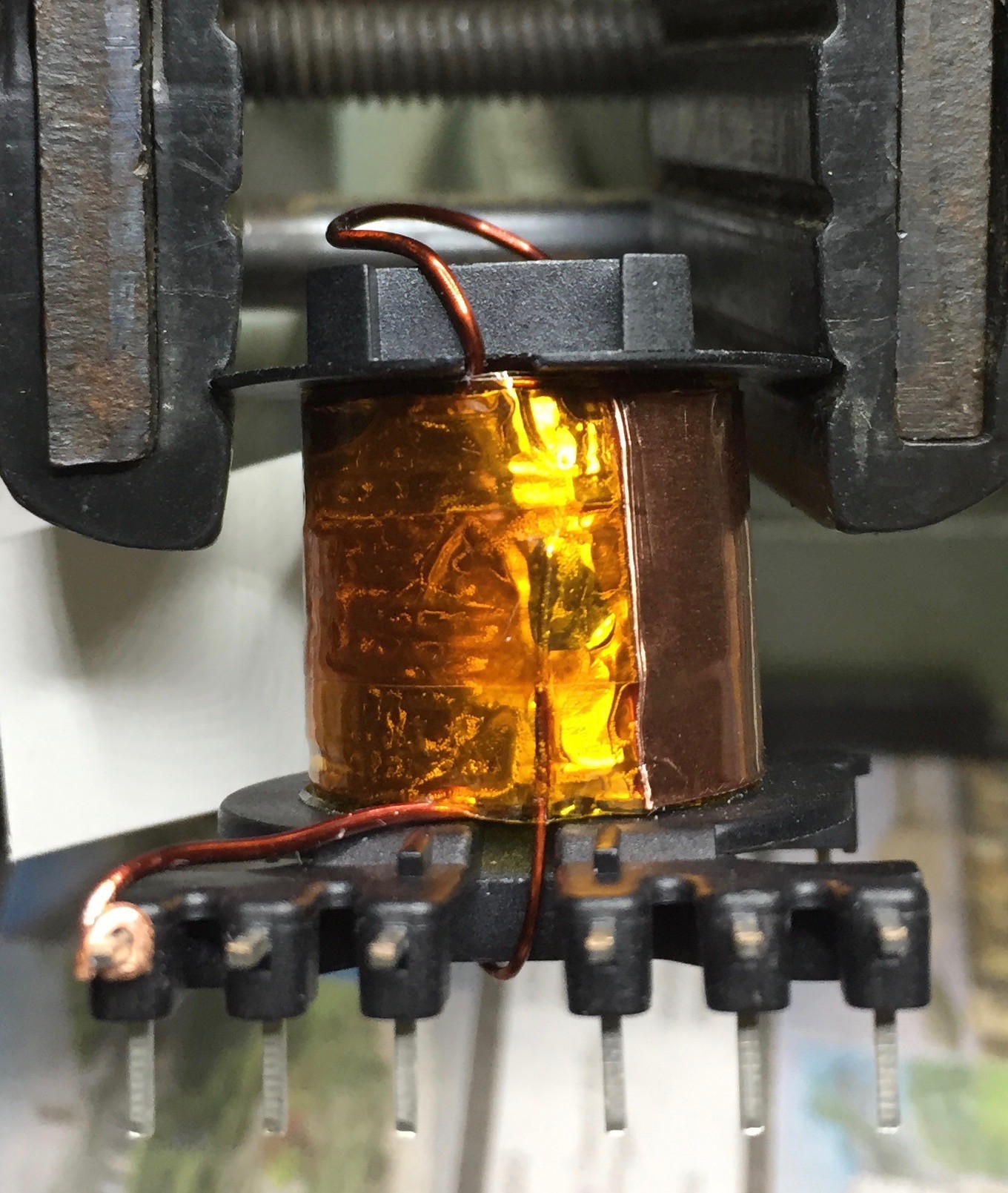
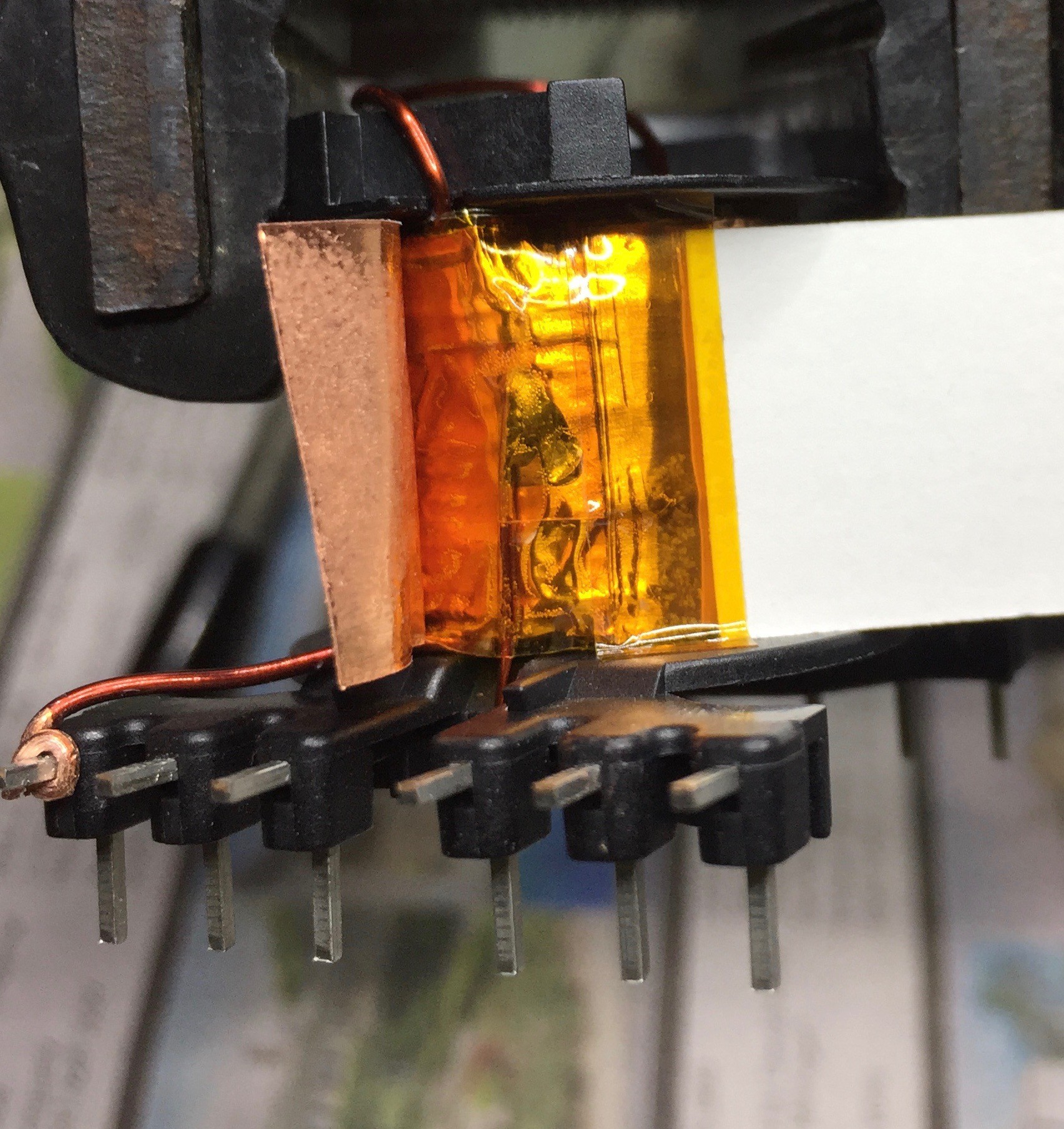
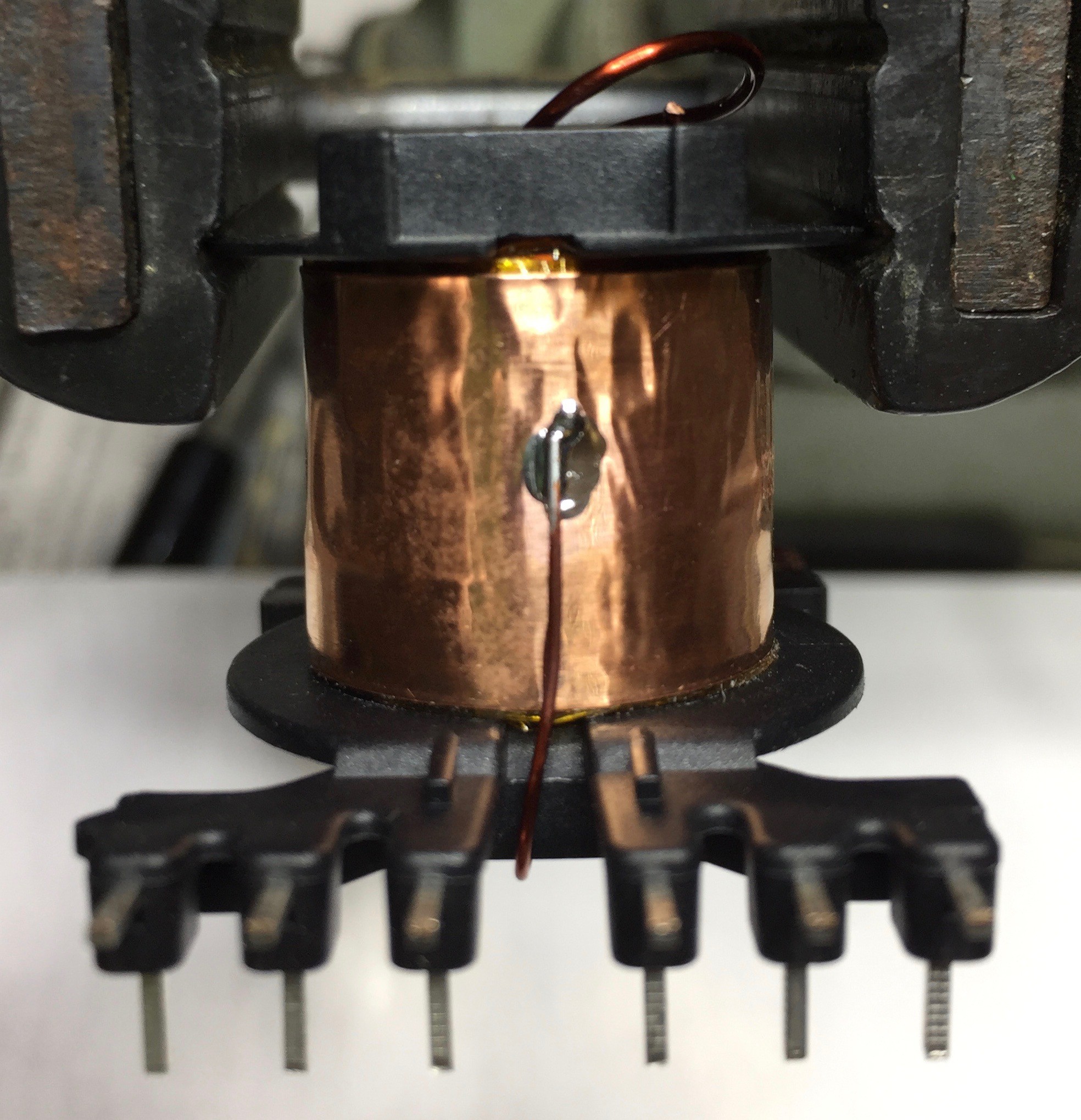
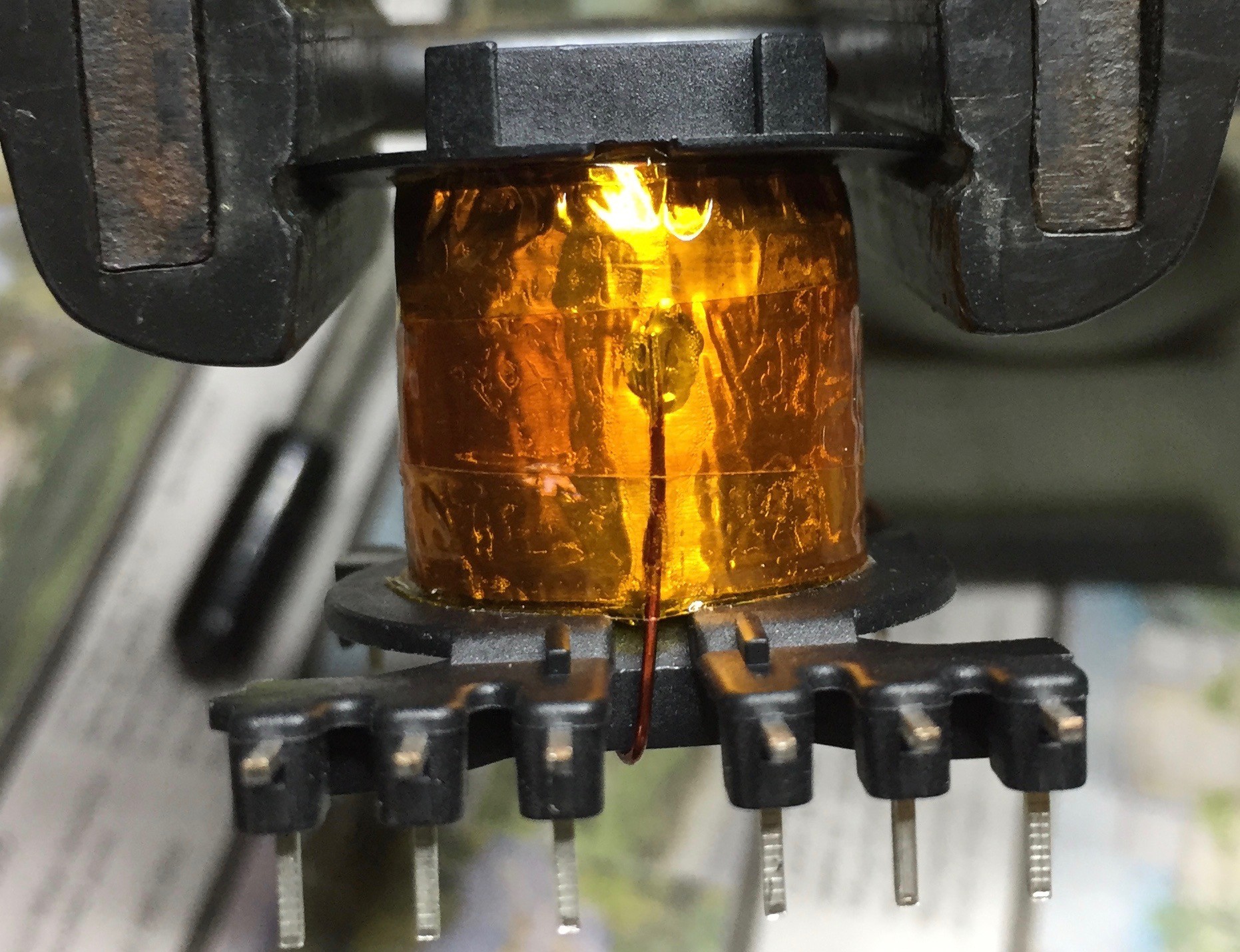
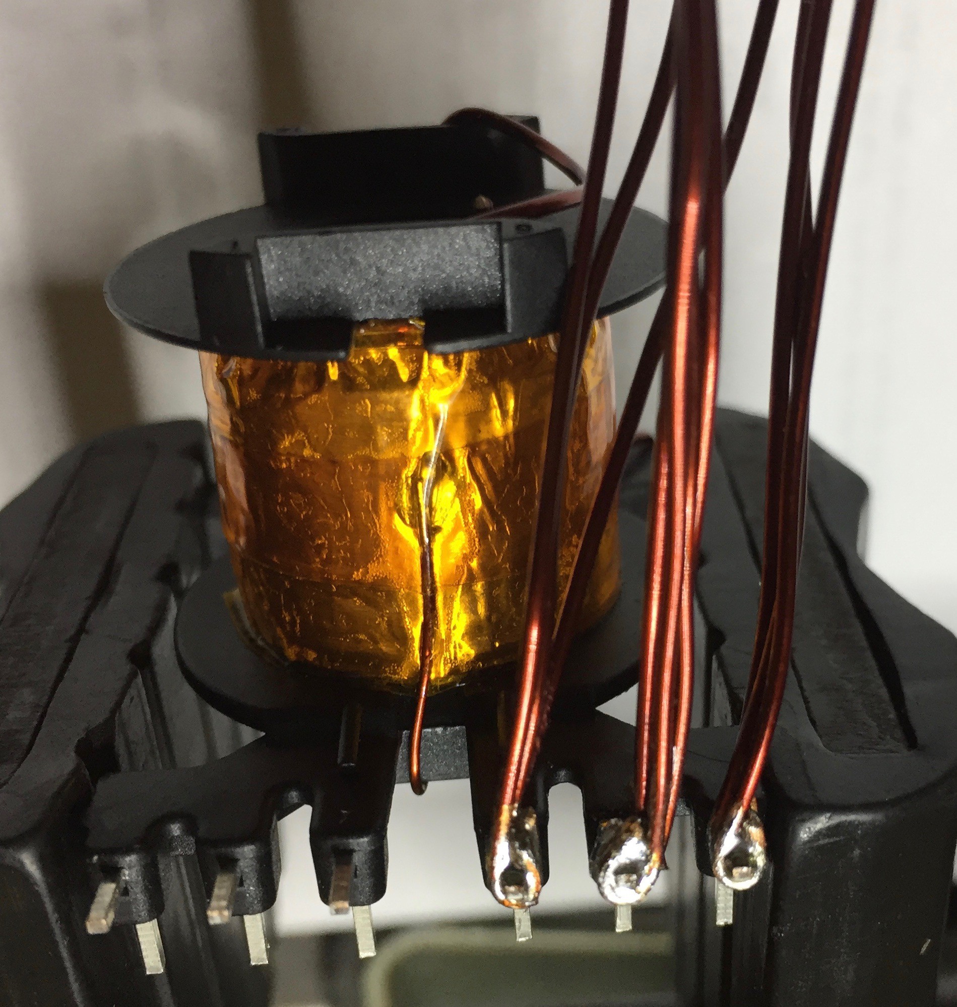
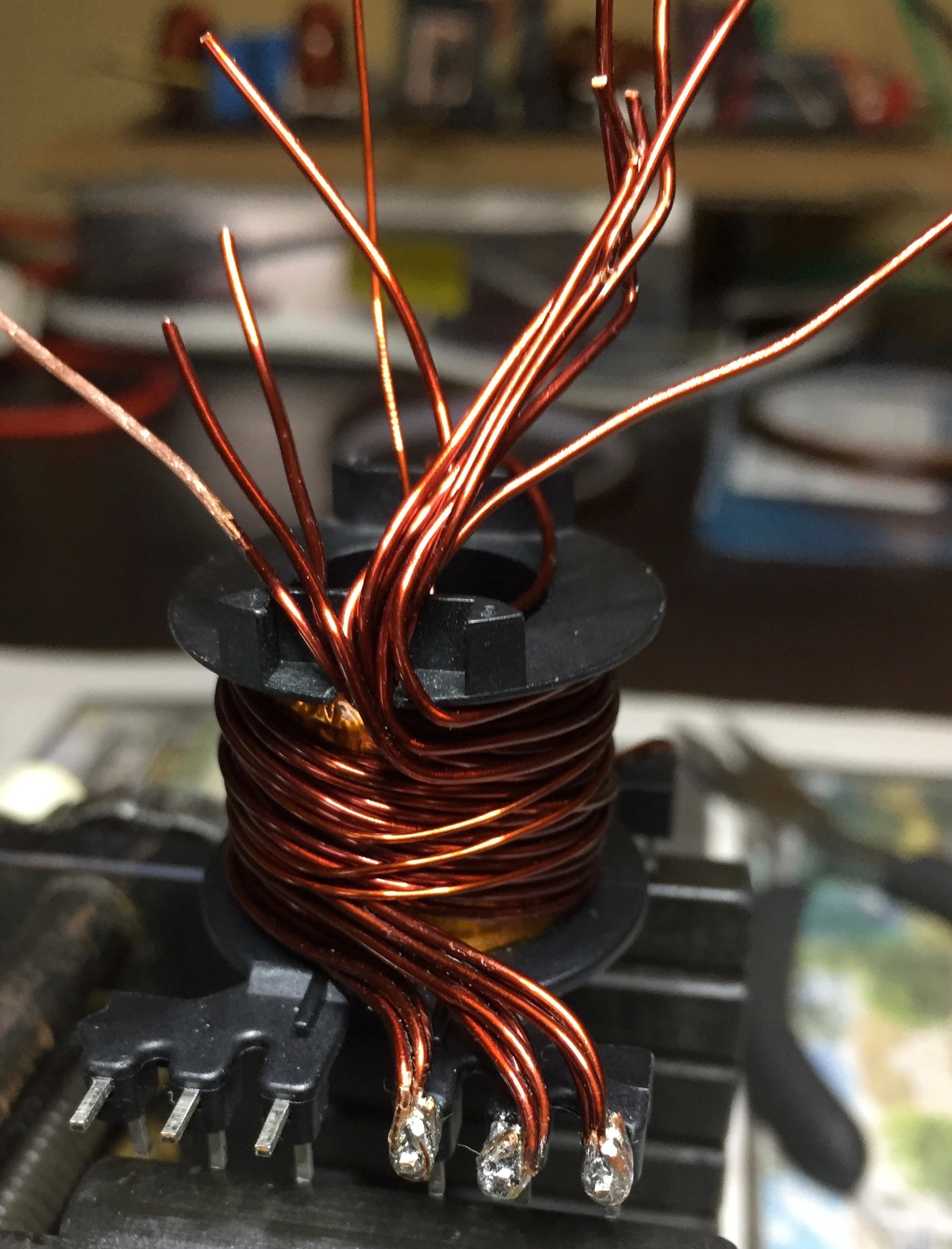
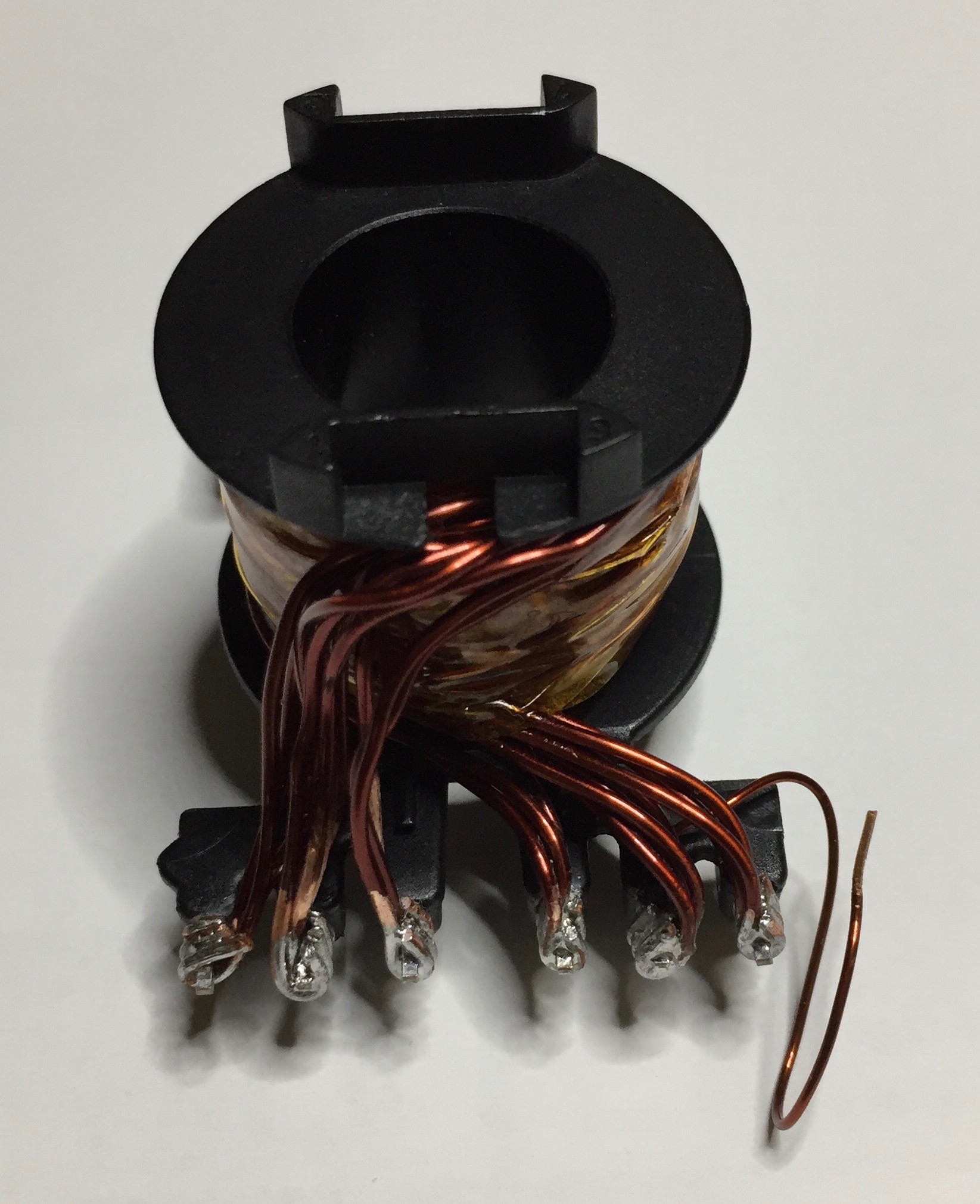

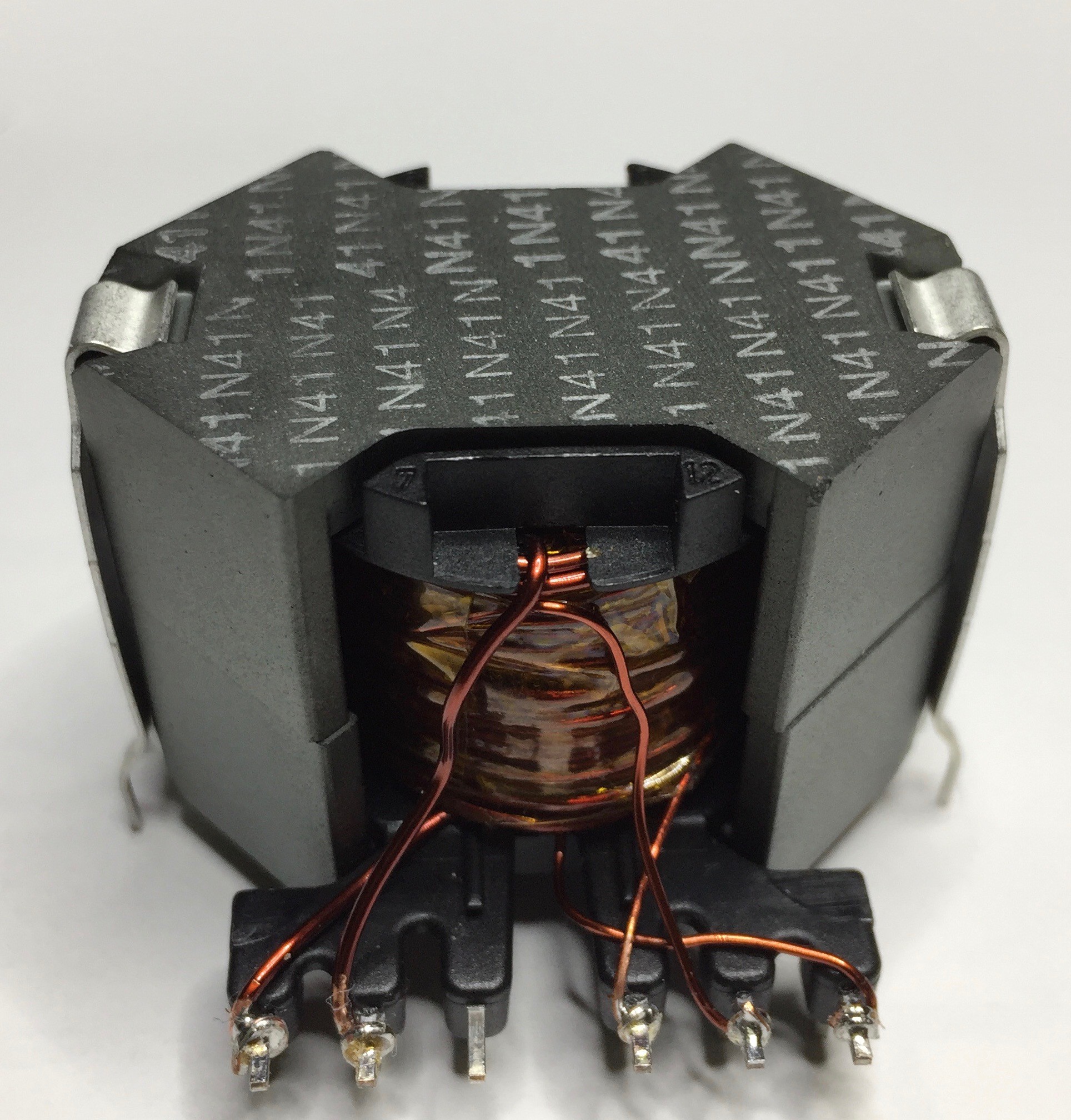
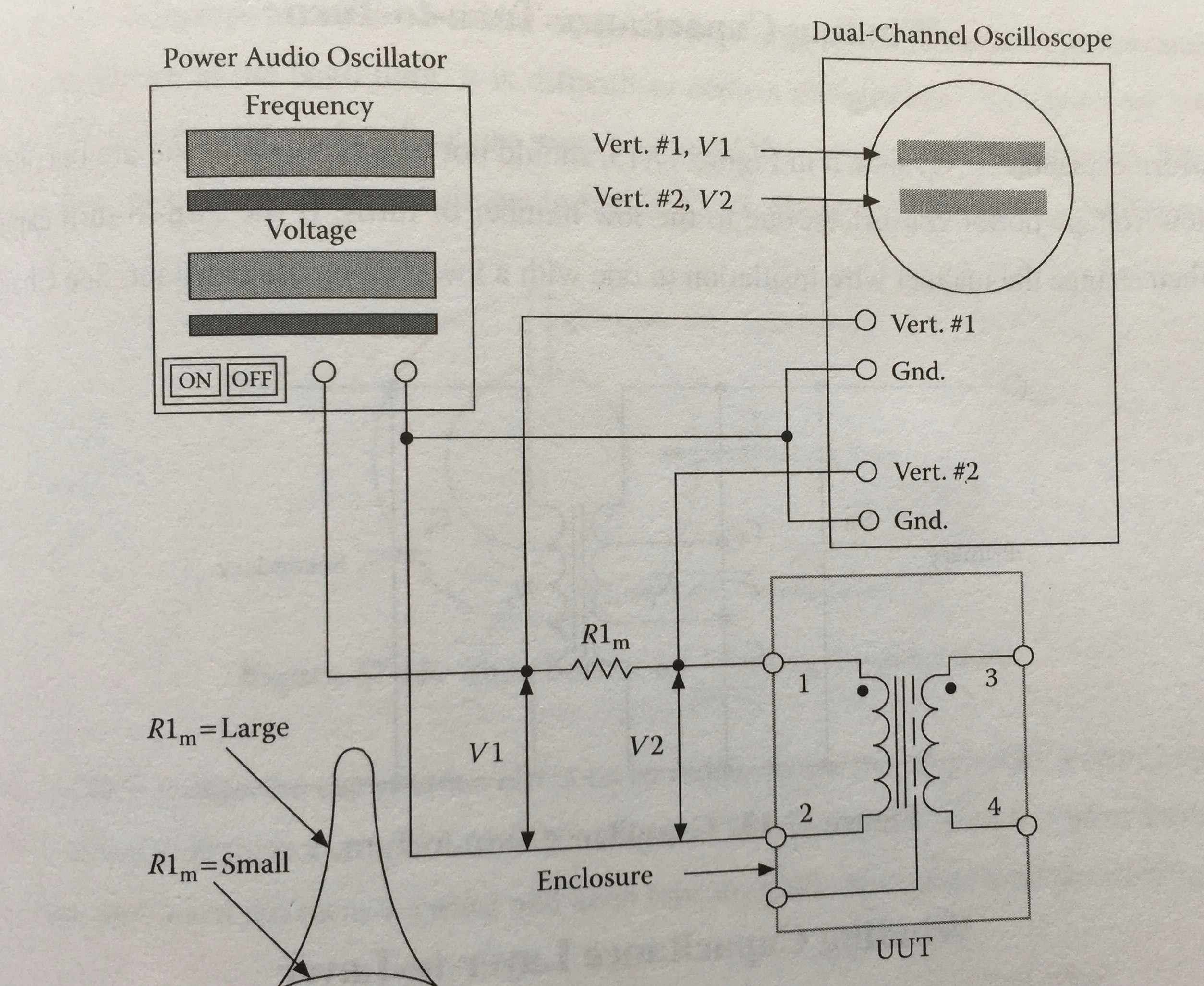
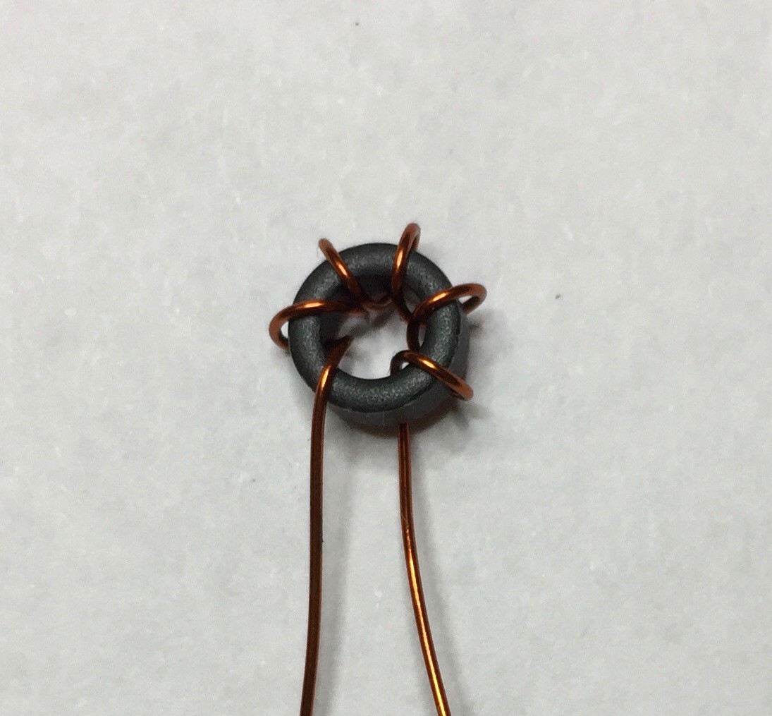


I had a DC blocking capacitor on the AC output in early prototypes but found it unnecessary. After that I didn't do much investigation on why but I suspect it's similar to the self-balancing effect you get with MOSFETs on the transformer bridge: an imbalance increases current on that leg of the bridge which raises junction temp, increasing their Rds(on), thereby reducing current. Somewhat ironic since the output inductors are designed as DC.
I haven't encountered problems running old-school gear. In fact, the cover photo with the TV has the audio running thru an early 90's Denon receiver/amp that uses a line transformer & linear supply.