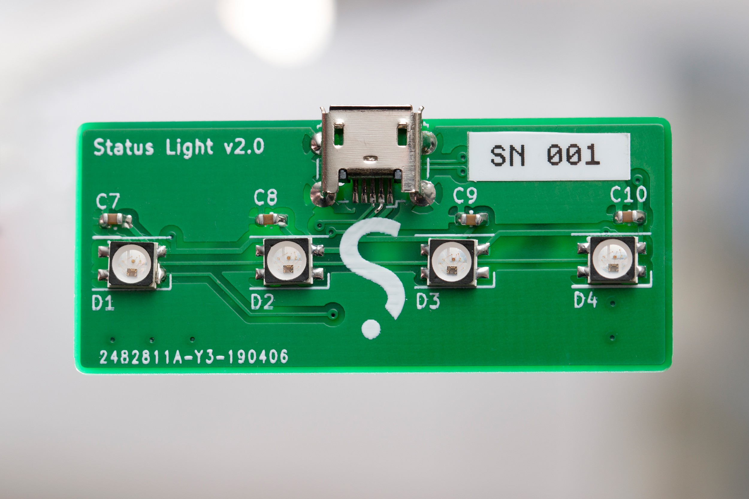
A slightly novelty notifier
To make the experience fit your profile, pick a username and tell us what interests you.
We found and based on your interests.
status-light-v1-enclosure-models.zipFusion360 and STL models for the original 2016 status light enclosure. This is only for archive.Zip Archive - 843.28 kB - 05/12/2019 at 09:57 |
|
|
status-light-v1-firmware-source.zipAVR-C source code for the original 2016 status light project. This is only for archive.Zip Archive - 116.58 kB - 05/12/2019 at 09:57 |
|
At 10pm on a Thursday evening in early April, it suddenly seemed like a great time to make another version of the status light I've been using for the last few years. Something small, simple and fun. Why not chuck together a schematic and a start a layout before calling it a night!
I'd been eyeing the STM32F070 for another project needing a basic, low-cost controller with a USB peripheral built in, and that seemed to fit the build here too. Sure, an ATTiny85 with V-USB is a little cheaper, but the options the STM32 brings to the table are worth the premium:
Most of these are overkill for a device that controls a handful of addressable LEDs, but the smooth remote debugging experience is probably worth the cost alone. The STM32 does need 3.3V regulation, but the part count is reduced overall compared to the V-USB approach.
There's not a whole lot to this piece of hardware. All of the spare pins on the micro are broken out so this can be used as a mini dev board for other devices that need USB control.
A few notes for next time:
PA0
). This is fine for bit-banging the LED data signal, but on this MCU model (C6
), PA0
has no useful special function! An SPI or UART peripheral could've been used to encode the SK6812's time-based signal as bytes and sent via DMA instead of blocking for 115uS, but it's not a big deal for this project.Again not much to see here. The pictured layout is slightly improved over the design that went to the fab - "2.0a" fixes an unnecessarily long ground return path for the crystal, though this hasn't caused any issues in the boards I had made so far...
I'd previously bought all of the components needed for this build, so I sent the board off and moved onto other projects while waiting. The PCB manufacture only took a couple of days, but the standard-post shipping I chose took significantly longer.
Three weeks later, the PCBs arrived and I spent an evening at the bench soldering. Assembly went fairly smoothly, with the regulator installed and tested first, then the STM32 installed and confirmed accessible over SWD:
The SK6812-mini LEDs went on, and toggling their data pin as fast as possible confirmed they were all working at full brightness. A little NOP wrangling later, the correct time-based data signal could be sent and the LEDs were ready to work. The encoding has slightly different timing than the WS2812(B), but it's the same concept.
The first issue arose when the board wouldn't communicate...
Read more »A couple of years ago I was part of the site-reliability team at Xero - a squad of in-flight cyber mechanics outnumbered 100 to 1 by a fleet of production servers. To cut through the daily noise of alerts, logging and system metrics, I figured a simple light on my desk to say "something's not right" would be a useful novelty. The catch? This was my second electronics projects, and I had no idea what I was doing.
Searching for "usb controllable led" in 2019 lists a bunch of devices you can outright buy, but back when I started this project in 2016 there didn't seem to be much around. At the time I referenced a single article about a "USB status cube" someone had built, but searching for that article now turned up numerous projects doing exactly the same thing as I ended up with: an AVR chip, V-USB and a bunch of programmable LEDs. I have no idea how I missed all of these at the time, but we can chock it up to blissful ignorance.
In any case, this is the story of my first PCB and how it's still a useful tool almost three years later. This isn't a build guide, but if you're building something similar you can use this as an example of what not to do.
In my first electronics project I'd skipped a schematic and PCB and simply used point-to-point wiring and some strip-board to hack it together. For the status light, a PCB was needed to arrange 9 surface-mount LEDs in a fixed pattern, along with the SMD WS2811 chips and microcontroller.
Now keep in mind at this point I had never laid my hands on any EDA software. I grabbed a copy of Eagle (because that's what I'd seen other people using - I recommend KiCAD now) and set to work bashing my fists on the keyboard until this monstrosity came out:
Among the overlapping, diagonal wires, lack of decoupling capacitors, lack of meaningful labels (what are those USB pins!!?) and haphazard organisation, I'd give this an F for "functional but utterly terrible". It definitely captures the "I have no idea what I'm doing, but I have a goal to achieve" spirit that comes with being a total newbie.
The crisscrossing wires were introduced during layout to make it possible to route the board single-sided, but it's a gross schematic regardless. Also note that the LEDs were desoldered/borrowed from a 12V WS2811 strip that used groups of generic RGB LEDs with separate driver ICs, so even though this design has 9 LEDs it's only three addressable columns.
For reference, here's the USB part of the schematic recreated to be actually meaningful:
Choosing to create a single-sided board with 50+ connections for my first PCB layout experience taught me two things:
You might notice that the layout pictured is version 1.2. The first attempt (picture) ended up a complete mess of bodges as I'd missed a reset pull-up for the AVR, had multiple unconnected ground pours, and had mirrored the ISP header. The original version also had one less LED in the centre column, which gave uneven brightness so a third was added.
I won't go into detail about making the PCB at home other than saying it taught me to avoid making PCBs at home unless absolutely necessary. Sure, do it once as a learning experience, but then you'll understand why it's usually better to pay someone else to do it.
The firmware for this original version of the project isn't particularly interesting or good, but you can download...
Read more »
Create an account to leave a comment. Already have an account? Log In.
Become a member to follow this project and never miss any updates
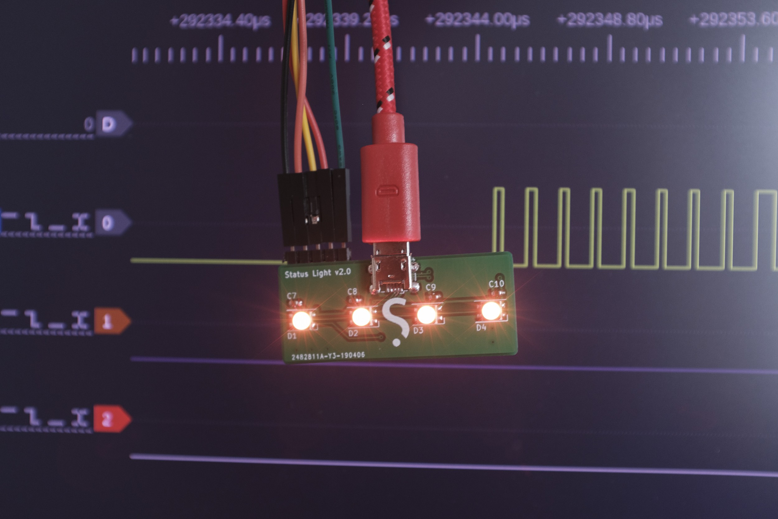
Are you selling these Status Light v2.0 boards?