Tensioning Timing Belts and Light-weighting the Legs:
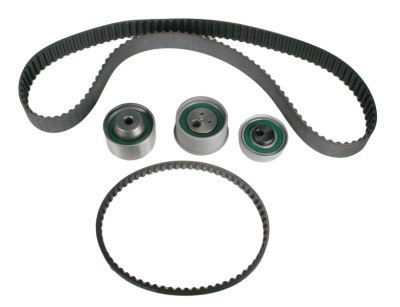
Up to this point in the design of the Leg Assembly, the timing belts haven’t had a method of tensioning. Normally in timing belt system design, an idler with an offset cam is utilized to provide the desired amount of tension (shown in the first picture below). However, I was unable to find a vendor for an offset cam timing belt tensioner that fit within the limited space and budget.
I designed a simple alternative solution. Instead of an offset-cam tensioner, I decided to add a plate to the Leg Motor Box Assembly with a series of ¼”-20 tapped holes at various heights. This plate enables small idler pulleys (essentially ¾”-diameter aluminum with two pressed pulleys to be mounted into any of the holes, providing any stepwise desired amount of tension.
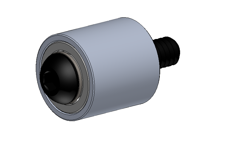
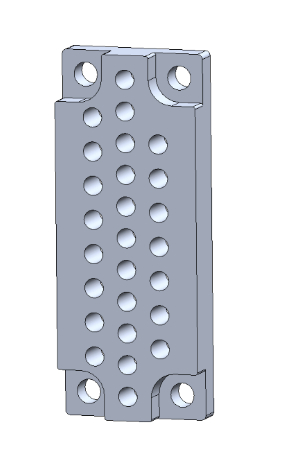
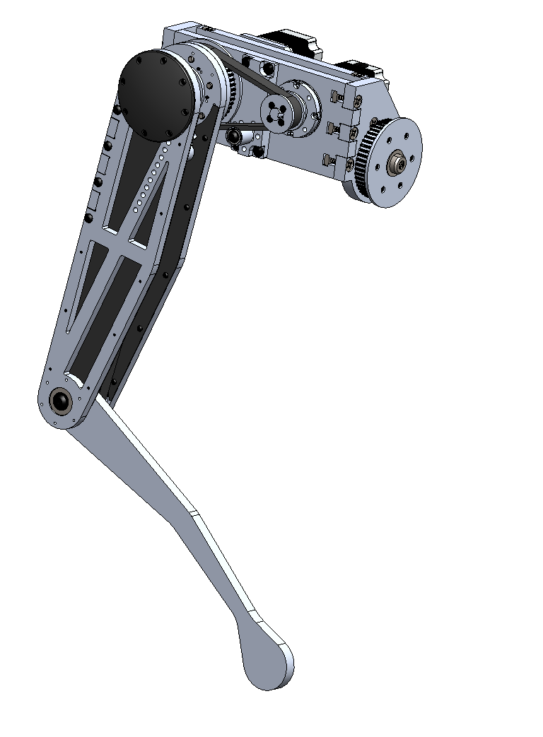
I then continued by adding a similar tensioning mechanism to the upper-leg assembly. Rather than three rows of offset holes, the longer geometry of the upper leg allowed me to add fewer holes at a small angle to the length-wise side of the edge of the timing belt that powers the lower-leg. For cosmetic reasons and to keep dust out of the upper-leg bearings, I also decided to add a 3D-printed bearing shield. In the short-term (just after the design is finished), I’ll print these on a Form 2 of Prusa – long-term I’ll have them printed very inexpensively using Multi-Jet Fusion through a 3D printing service bureau.
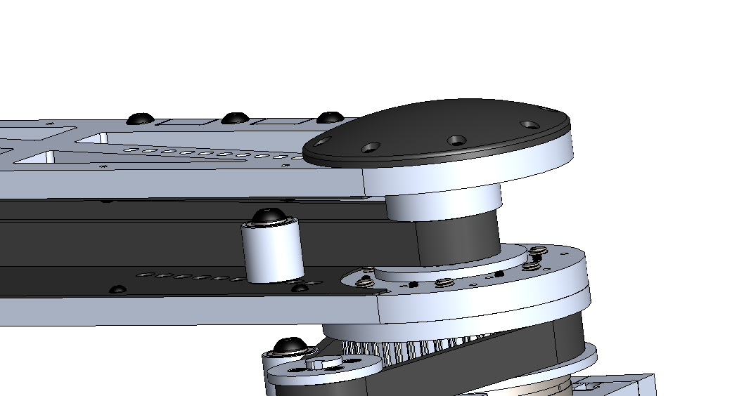
In order to minimize rotational inertia in the upper legs, I spent some time light-weighting Spike’s upper legs, while being sure to keep enough material to make sure the tensioner inside the upper leg assembly operates without issue. I also added waterjet carbon fiber plates to the inside of Spike’s legs for some additional rigidity and to make Spike more cosmetically-pleasing, though this step is unnecessary if you’re replicating Spike (unless you like the look, of course!). At this point, a full Leg Assembly has been designed designed, complete with an upper-leg, lower leg, and hip joint to provide three degrees of freedom. From here, I’ll have to mirror this assembly for the other three legs, and begin designing Spike’s body.
 Michael G
Discussions
Become a Hackaday.io Member
Create an account to leave a comment. Already have an account? Log In.