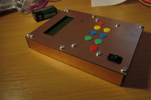
(AT) Mega Enigma, a 2560 Pro Mini Enigma Simulator
A minimalist 139x171x50mm Enigma Machine Simulator with working plugboard using an ATmega 2560 Pro Mini and a custom PCB.
A minimalist 139x171x50mm Enigma Machine Simulator with working plugboard using an ATmega 2560 Pro Mini and a custom PCB.
To make the experience fit your profile, pick a username and tell us what interests you.
We found and based on your interests.
aa-battery-system-ponoko.svgAll the pieces needed to add an AA battery compartment to a laser cut enclosure.svg+xml - 808.48 kB - 01/14/2020 at 01:42 |
|
|
aaa-battery-system-ponoko.svgAll the pieces needed to add an AAA battery compartment to a laser cut enclosuresvg+xml - 798.00 kB - 01/14/2020 at 01:42 |
|
|
The PicoEnigma boards were hard to solder because the part footprint for the Arduino Mega has an error, the pads are too large. When laying traces between pads, the traces do not have soldermask between traces and pads, solder bridges can occur between the sides of a trace and adjacent pads.
To detect this issue, run a DRC check with DRC Settings to "Professional" 0.01 If any issues pop up, fix them.
Fritzing Hack 1 : Fix issues with an existing part:
Create a new folder to hold the part being edited
Export the original part to this folder, rename the file from .fzpz to .zip and extract all the files
(delete .zip file after extracting files)
To create a new unique part name, increase the filenames by 1 (xxxx_2_pcb.svg - xxxx_3_pcb.svg)
Edit .fzp file using notepad++ and increase the filenames by 1 to correct the file names referenced inside
Edit the _pcb.svg file and manually adjust the size of the pads (change radius and stroke width)
Change one entry under the "copper0 group", change the values of r="xx" and stroke-width="xx" for a "<circle" tag
Confirm changes in svg files using Inkscape.
This example shows the new part being changed back to the old bigger values.
hange the remaining entries and verify with Inkscape.
Add all the files to a new zip file and rename to .fzpz
Import new part into Fritzing.
Fritzing Hack 2: Replace a bad part with a better part without affecting the routing.
To replace this part in an existing fzz file that uses it:
Create a new folder to hold the modified Fritzing board file.
Copy the .fzz file to be edited to this new folder.
rename the .fzz file to .zip, extract all the files
(delete .zip file after extracting files)
delete all files for old part
part.xxMYPARTxx_n.fzp
svg.breadboard.xxMYPARTxx_n_breadboard.svg
svg.icon.xxMYPARTxx_n_icon.svg
svg.pcb.xxMYPARTxx_n_pcb.svg
svg.schematic.xxMYPARTxx_n_schematic.svg
where _n_ is the version number for the old part
copy all files for new part from the modified parts folder created
verify the new files have a version number _m_ different from the old files
edit .fz file and correct the file reference for old part (change _n to _m in the line referencing MYPARTxx_n.fzp )
(increase part filaname by 1 to change to filename for new part)
Add all the files to a new zip file and rename to .fzz
Open file with Fritzing, verify traces go into pads
Export for production as gerber, load them to OSHPark and verify the copper goes all the way into the pads and that there is soldermask between traces and pads.
If Fritzing shows an error message saying that it cannot save the XXXX_drill.txt and/or XXXX_pnp.txt,
the path to the gerber files is too long, move the folder closer to the root of the drive (133 characters is too long)
This is a permanent fix, the resulting Fritzing .fzz file can be edited normally
Fritzing Hack 3: Correcting hole sizes in gerbers:
This procedure is used to adjust drillbit sizes after gerber files have been exported. This is not a permanent fix, but a gerber hack.
This change will have to be re-applied if the gerber files are exported again from a .fzz file
Export the fzz file for production as a gerber file
open drill file and verify drillbit size for new part is the same as old part
The drill file starts with definitions
; NON-PLATED HOLES START AT T1
; THROUGH (PLATED) HOLES START AT T100
M48
INCH
T1C0.137795
T100C0.039370
T101C0.038000
T102C0.100000
Each line defines a hole diameter and assigns it to a drillbit name.
This means that a drill (T101) is defined as being a (0.038 inch) hole
T1 is a mounting hole (non plated), T100 thru T103 are holes going through copper pads.
Further down we see
T101
X013095Y011636
X026095Y012636
X014095Y002636
X026095Y018636
meaning that the drilling machine now changes to bit 101 and starts hitting the X and Y coordinates listed
There are 96 lines below the T101 line...
Read more »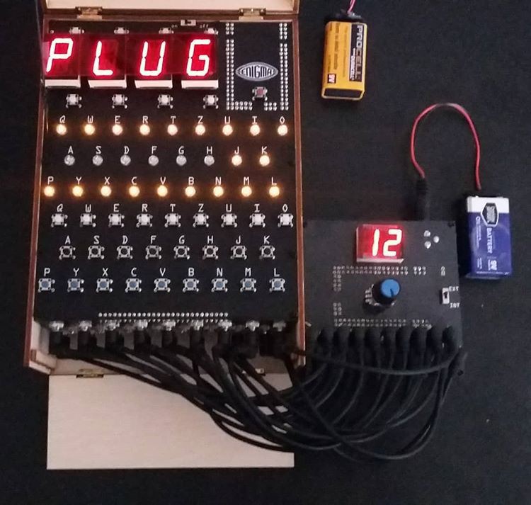
An external UHR Switch attachment has been developed for Mega Enigma
UHRSwitch page:
https://arduinoenigma.blogspot.com/p/uhrswitch-uhr-switch-for-megaenigma.html
BOM:
https://arduinoenigma.blogspot.com/2020/10/uhr-switch-bill-of-materials-bom.html
Theory of Operation:
https://arduinoenigma.blogspot.com/2020/05/designing-uhr-switch-for-arduino-based.html
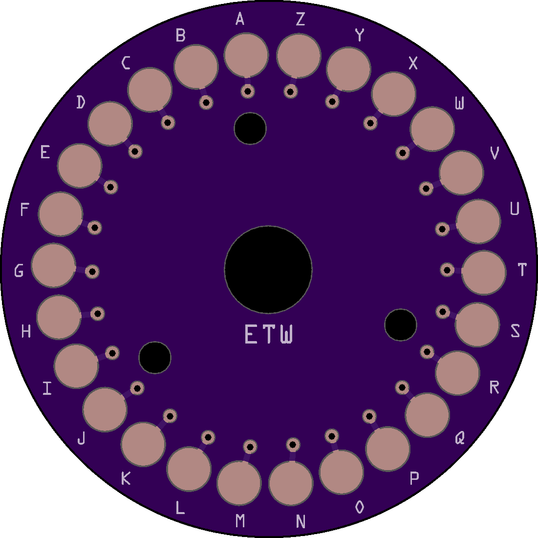
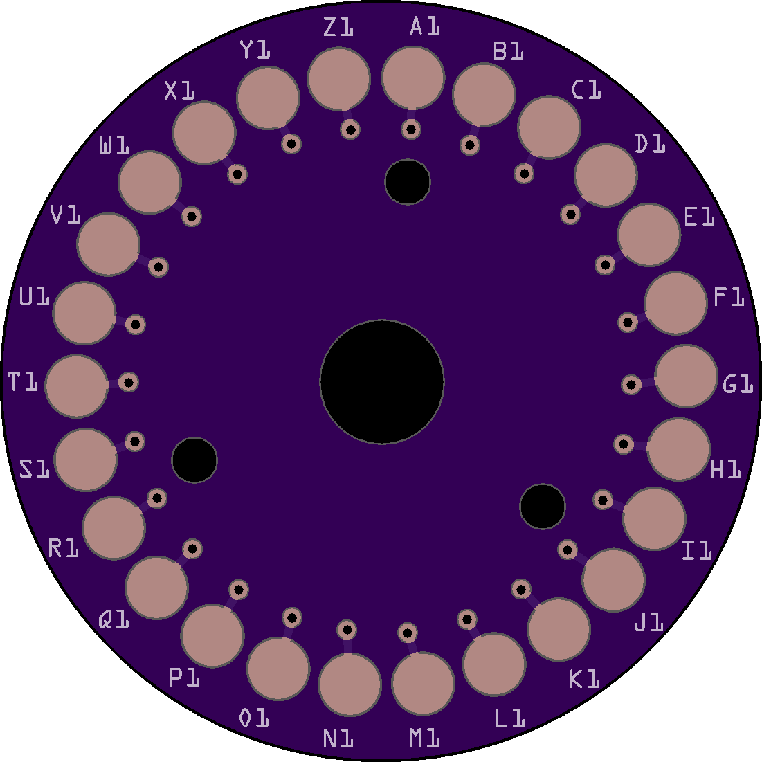
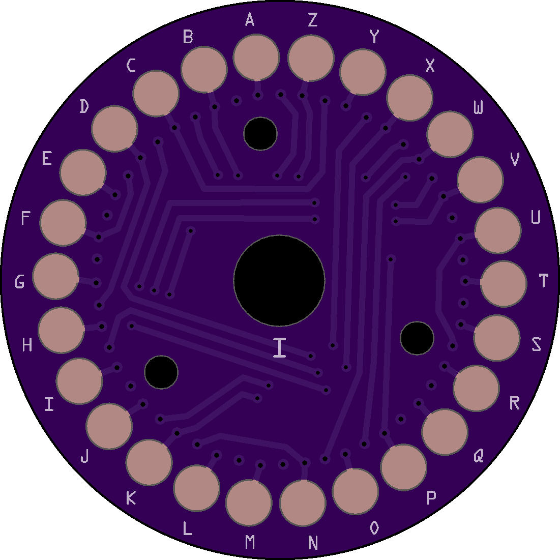

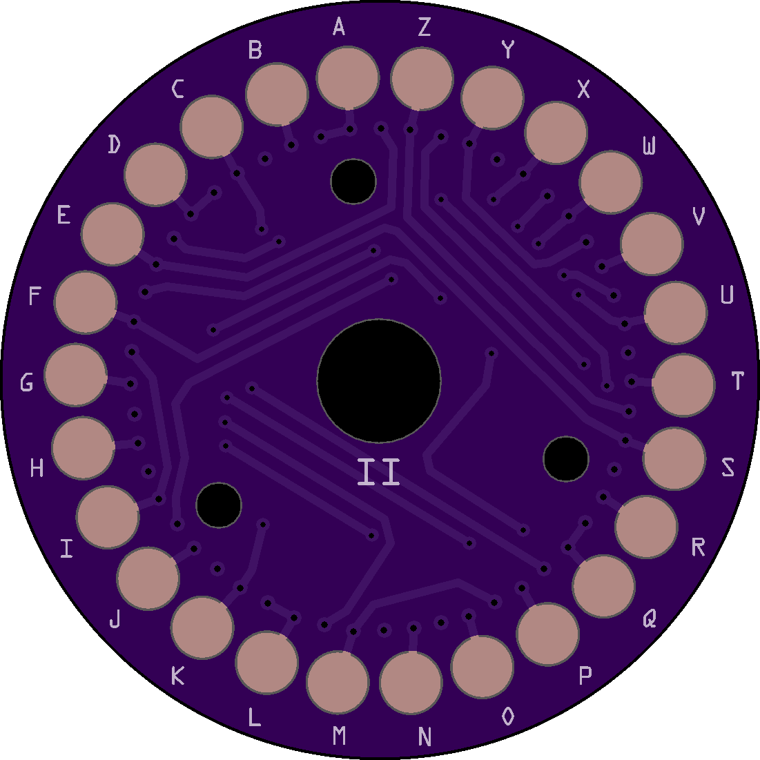

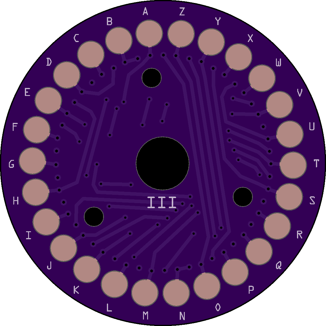
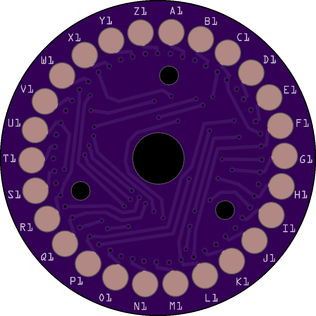
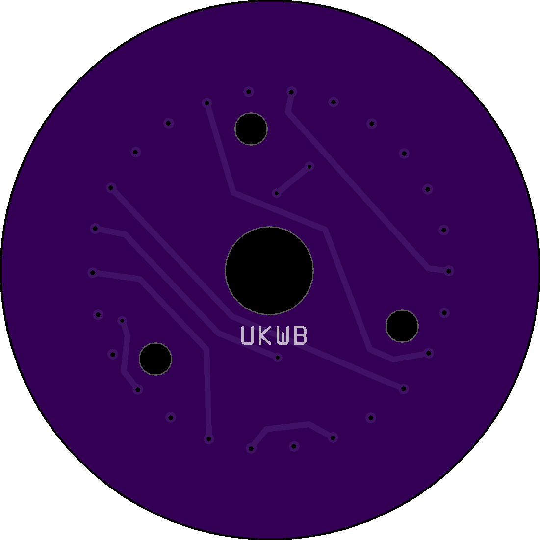
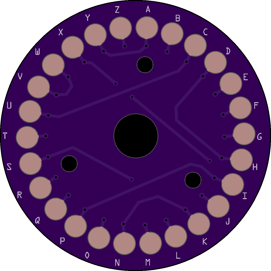
And finally, here is a picture of completed units:
Enigma Uno:
https://www.tindie.com/products/arduinoenigma/arduino-enigma-i-m3-m4-machine-simulator-w-case/
NanoEnigma:
https://www.ebay.com/itm/114230592101
PicoEnigma:
https://www.ebay.com/itm/114219267074
https://www.tindie.com/products/arduinoenigma/picoenigma-a-universal-enigma-machine-simulator/
Introducing PicoEnigma.
Runs the same Universal Enigma Machine Simulator as MegaEnigma, but with a slightly changed IO Layer owing to its 14 segment displays.
https://arduinoenigma.blogspot.com/p/picoenigma.html
To put batteries inside a laser cut enclosure, one has to think in 3D using 2D:
The pictures in this article will show how:
https://arduinoenigma.blogspot.com/2020/01/how-to-put-battery-compartment-inside.html
And now that there is a built in battery compartment, then the question of how long will it run on batteries becomes more important.
The following article shows a method of measuring run-time by writing timing checkpoints to EEPROM, no external components needed.
https://arduinoenigma.blogspot.com/2020/01/measuring-battery-run-time-by-writing.html
This simulator already had 5 UKWD rewirable reflectors, 4 were available to be used with the M3 machine, the other with the KD. The D reflector wiring can be changed in the field. The 5 reflectors included are examples of known wirings used at some point in time.A mechanism was needed to change the actual wiring of the reflector in this simulator.
Adding an item now to the menu system is easier than developing it from scratch. It is just a matter of inserting an item in the existing menu system. The UKWD sub menu has two special features, it is skipped if the currently selected machine did not have a D reflector, and the user cannot leave that menu until the pairs specified are correct.
Read more here:
https://arduinoenigma.blogspot.com/2019/10/ukwd-added-to-mega-enigma-universal.html
We are at a stage of the project where things are getting standardized and optimized. The program needs to print a space every once in a while to separate groups of characters, as well as send the CR LF sequence to start printing things in a new line. We are curious what is the best way to do that.
Let's start by saying that the most efficient way to print strings is to wrap them in the F("") macro. This keeps the string in PROGMEM, otherwise the string is stored in PROGMEM, then at runtime it is copied to precious RAM before printing and it is possible to run out of RAM if the sketch uses a lots of strings.
Example:
Serial.print(F("HELLO WORLD")); // DO THIS, 18 bytes code, 0 bytes ramdon't do this:
Serial.print("HELLO WORLD"); // DON'T DO THIS, 26 bytes code, 12 bytes ramNow, what what is the most efficient way to print a single space to separate two characters printed elsewhere? How about a newline / CR LF sequence?
The sketch below was created to test different ways to print a space and a new line in between the A and B letters.
First a very basic sketch was created and compiled. The program size and ram usage were recorded.
void testSerialSpace()     /*xls*/
{
  Serial.begin(9600);
  Serial.print(F("A"));
  Serial.print(F("B"));
}

void setup()
{
  testSerialSpace();
}

void loop()
{
}
Then different ways to print a space and a new line were added, one at a time and the memory usage was obtained by subtracting it from the baseline program.
The moral of the story is that the most efficient way to print a space is simply:
Serial.print(F(" ")); // adds 8 bytes code, 0 ramThings got a little more surprising in the newline department.
The obvious and wrong choice would be to print an empty string using the F("") macro.
Serial.println(F("")); // adds 26 bytes code and 4 bytes ramBut this added a whopping 26 bytes of code and 4 bytes of ram. Not sure why.
After trying different combinations the most efficient way to send a newline is to do a regular print, not a println and send a hex escaped string with the CR LF sequence
Serial.print(F("\x0d\x0a")); // adds 10 bytes code and 0 bytes ramThis result was a little unexpected. but now we know.
The full results are listed below, ranking from most efficient to least efficient. The strings printed without F("") are at the bottom of the list, with the absolute worst ways to send a single new line clocking at 40 bytes of code and 4 bytes of RAM.
//
// moral of the story:
// to print a space, use Serial.print(F(" "));
// to print a newline, use Serial.print(F("\x0d\x0a"));
//
//  Only prints AB
//  Sketch uses 1,794 bytes (0%) of program storage space. Maximum is 253,952 bytes.
//  Global variables use 182 bytes (2%) of dynamic memory, leaving 8,010 bytes for local variables. Maximum is 8,192 bytes.
//
//  Serial.print(F("HELLO WORLD"));
//  Sketch uses 1,812 bytes (0%) of program storage space. Maximum is 253,952 bytes.
//  Global variables use 182 bytes (2%) of dynamic memory, leaving 8,010 bytes for local variables. Maximum is 8,192 bytes.
//
//  Serial.print("HELLO WORLD");
//  Sketch uses 1,820 bytes (0%) of program storage space. Maximum is 253,952 bytes.
//  Global variables use 194 bytes (2%) of dynamic memory, leaving 7,998 bytes for local variables. Maximum is 8,192 bytes.
//
//  Serial.print(F(" "));
//  Sketch uses 1,802 bytes (0%) of program storage space. Maximum is 253,952 bytes.
//  Global variables use 182 bytes (2%) of dynamic memory, leaving 8,010 bytes for local variables. Maximum is 8,192 bytes.
//
//  Serial.print(F("\x0d\x0a"));
//  Sketch uses 1,804 bytes (0%) of program storage space. Maximum is 253,952 bytes.
//  Global variables use 182 bytes (2%) of dynamic memory, leaving 8,010 bytes for local variables. Maximum is 8,192 bytes.
//
//  Serial.print(" ");
//  Sketch uses 1,810 bytes (0%) of program storage space. Maximum is 253,952 bytes.
//  Global variables use 184 bytes (2%) of dynamic memory, leaving 8,008 bytes for local variables. Maximum is 8,192 bytes.
//
// Serial.print(...
Read more »
Create an account to leave a comment. Already have an account? Log In.
Become a member to follow this project and never miss any updates
 Jari Tulilahti
 jaromir.sukuba
 Denver