 Mike Rigsby
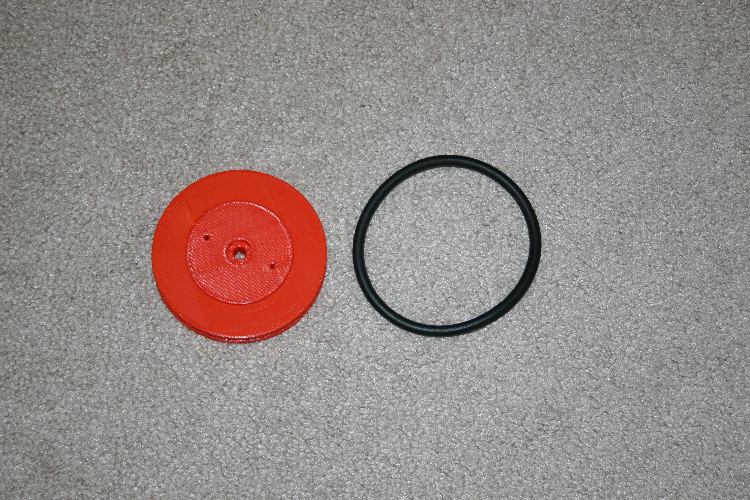
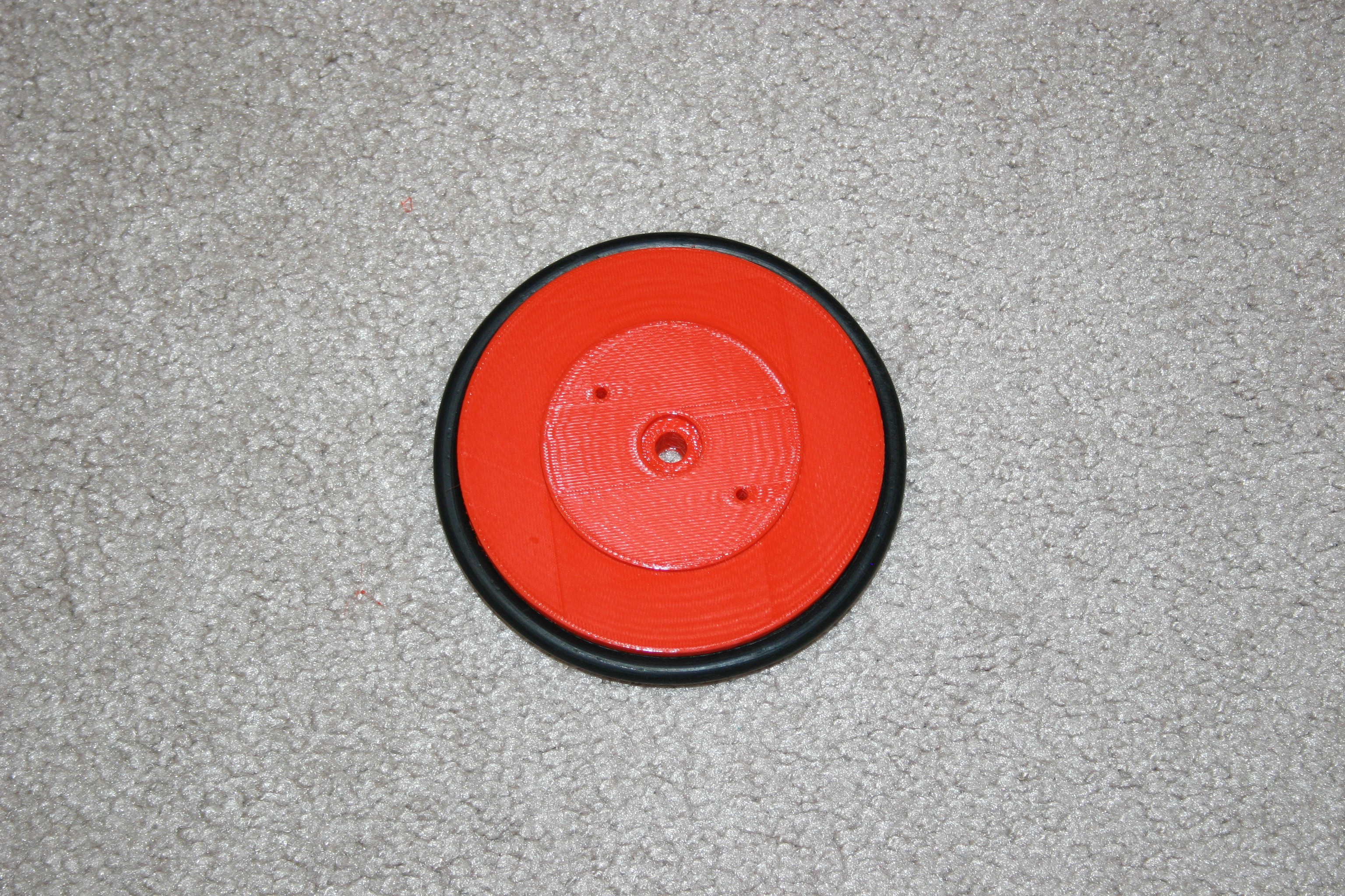
Take the 3d printed wheels and add vacuum cleaner belts for tires.
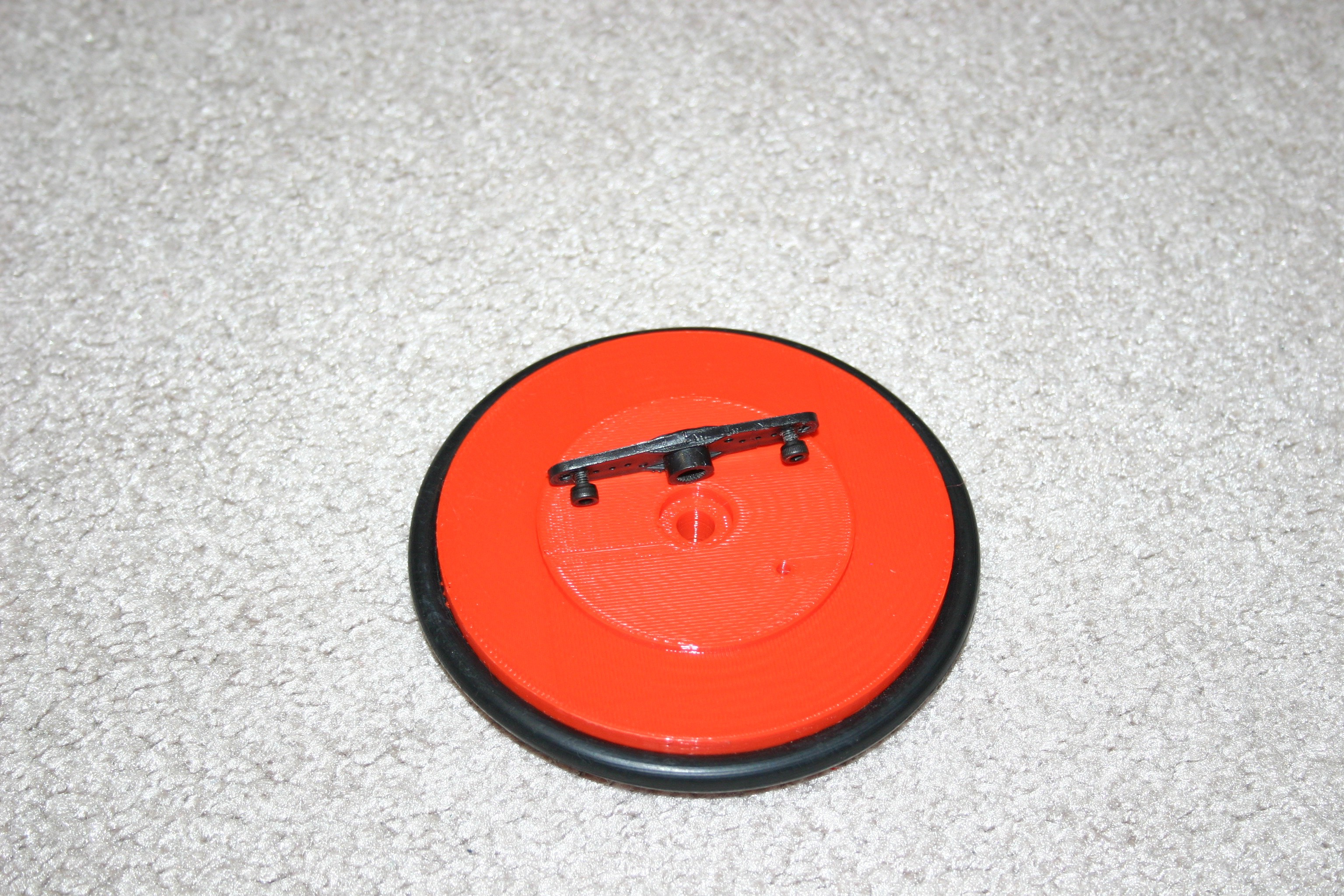
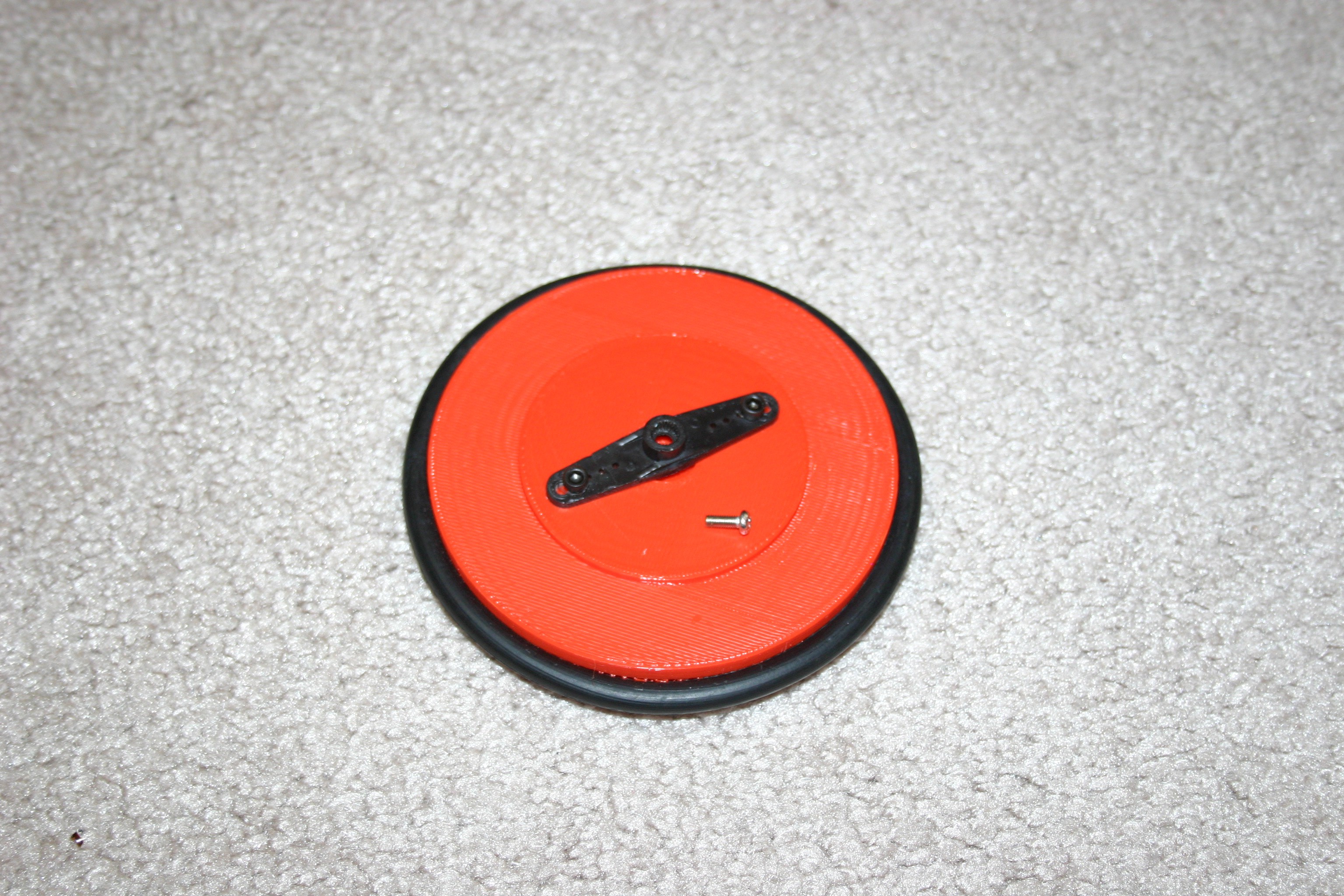
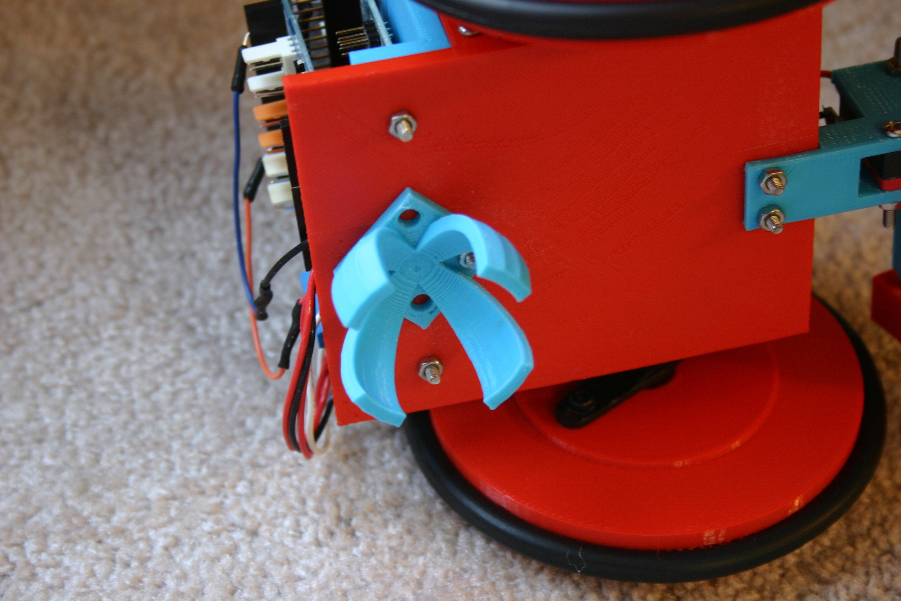
Attach the Servo horn using 3mm screws.
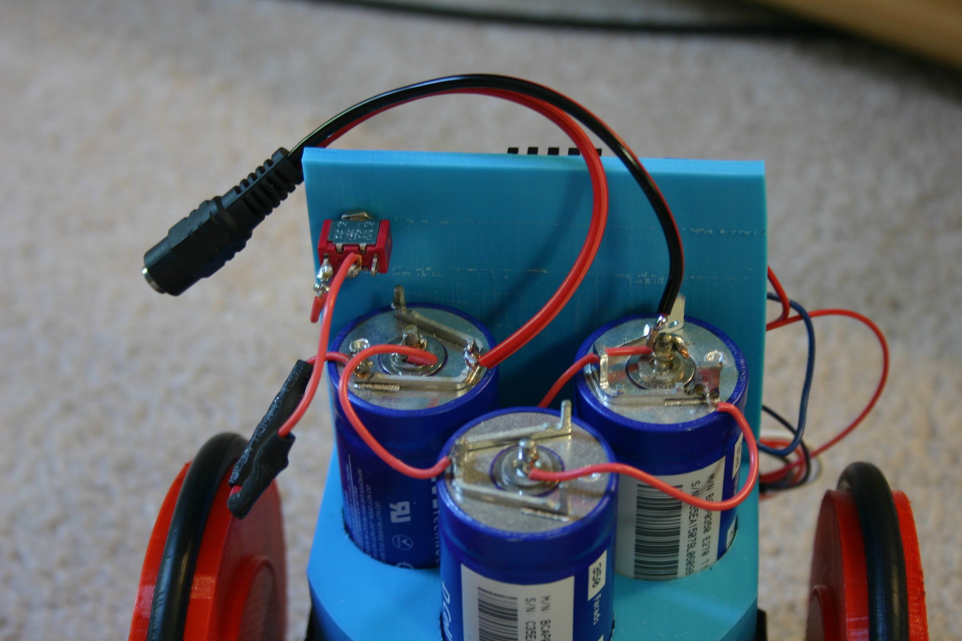
Solder the capacitors in series and place them in the 3d printed capacitor holder (along with the on/off switch). Solder the (female) charging cable.
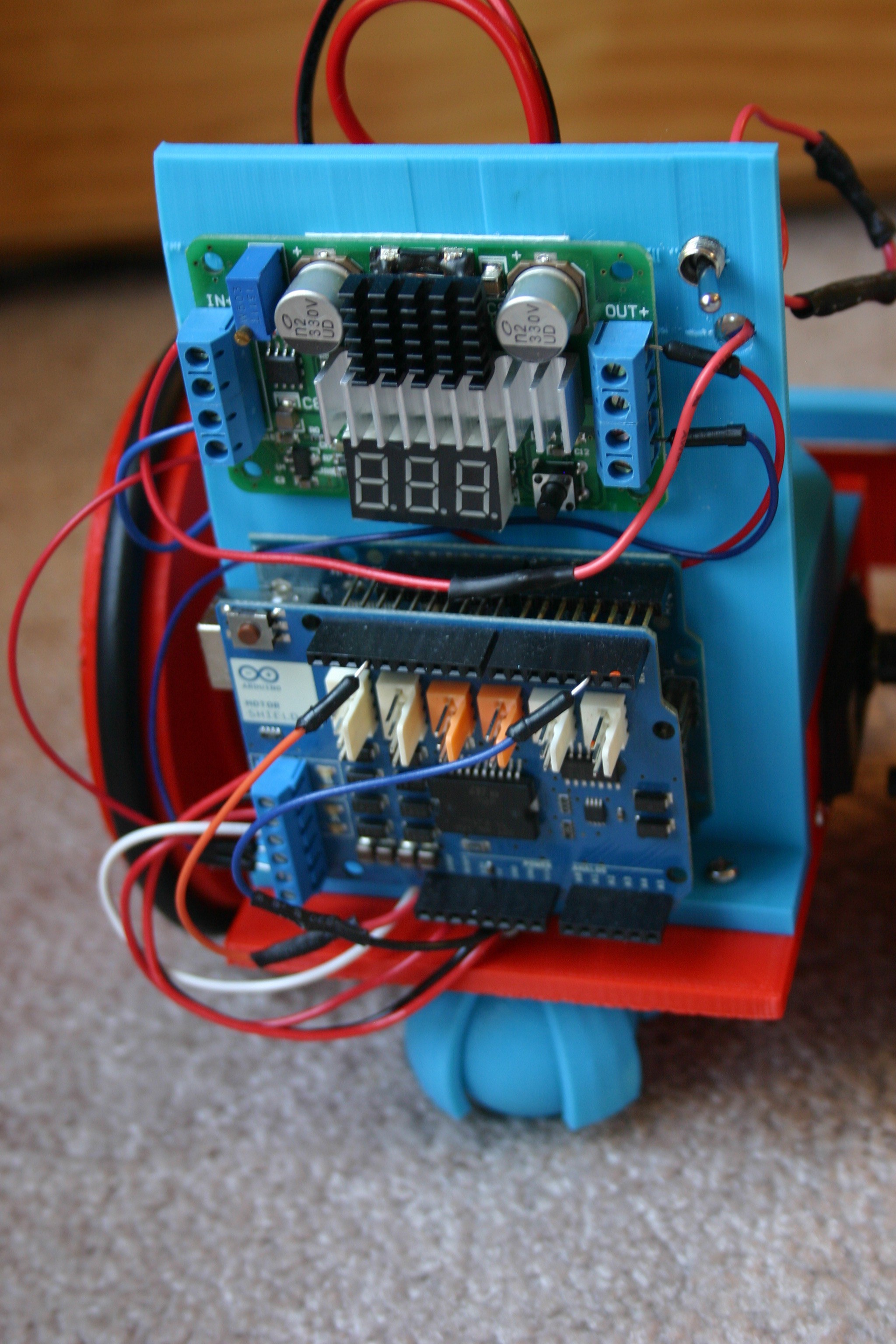
Attach the Arduino (with motor control shield) and dc-dc converter to the back of the blue capacitor holder. I used velcro for attachment.
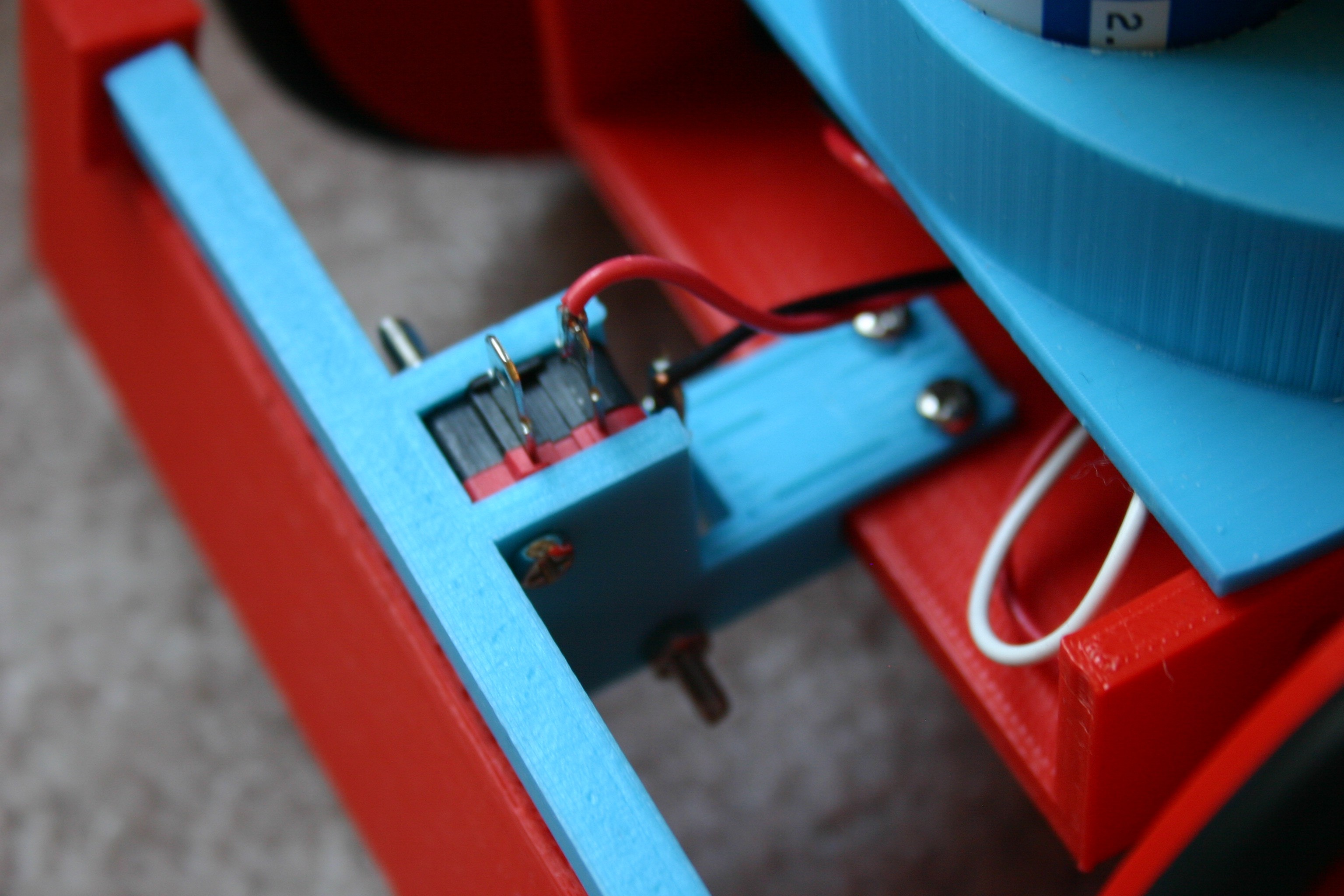
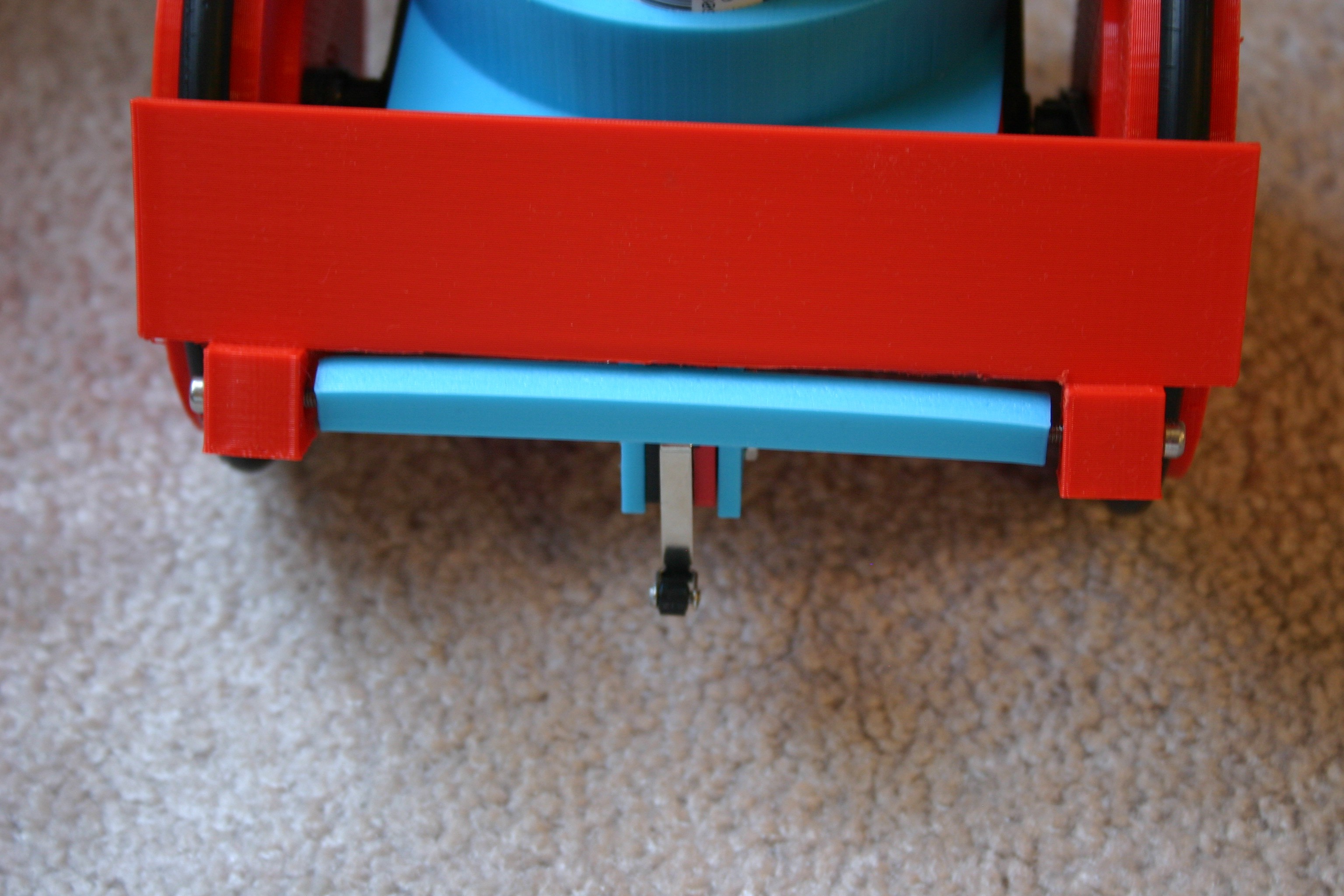
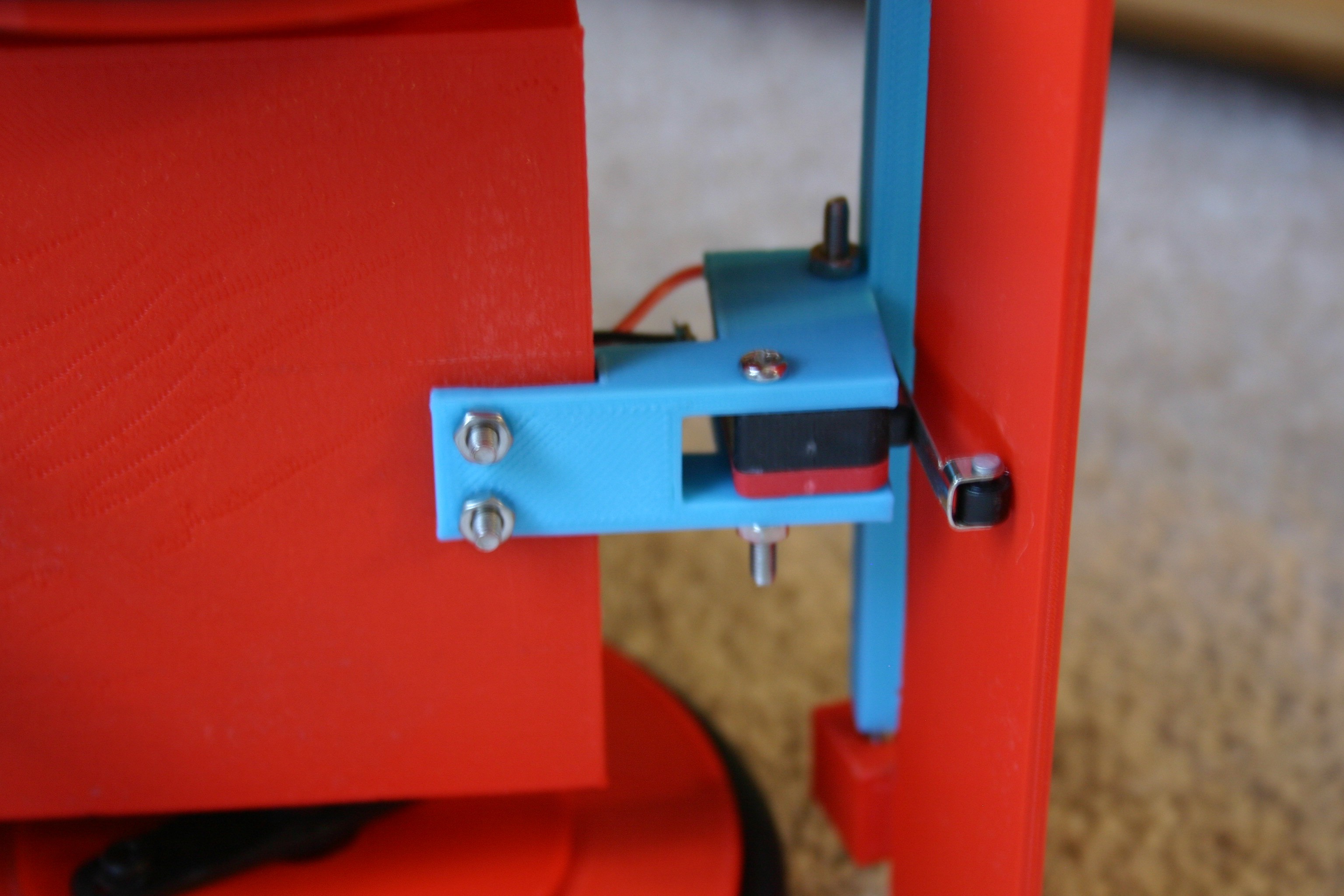
Attach the lever switch and bracket to the robot body.
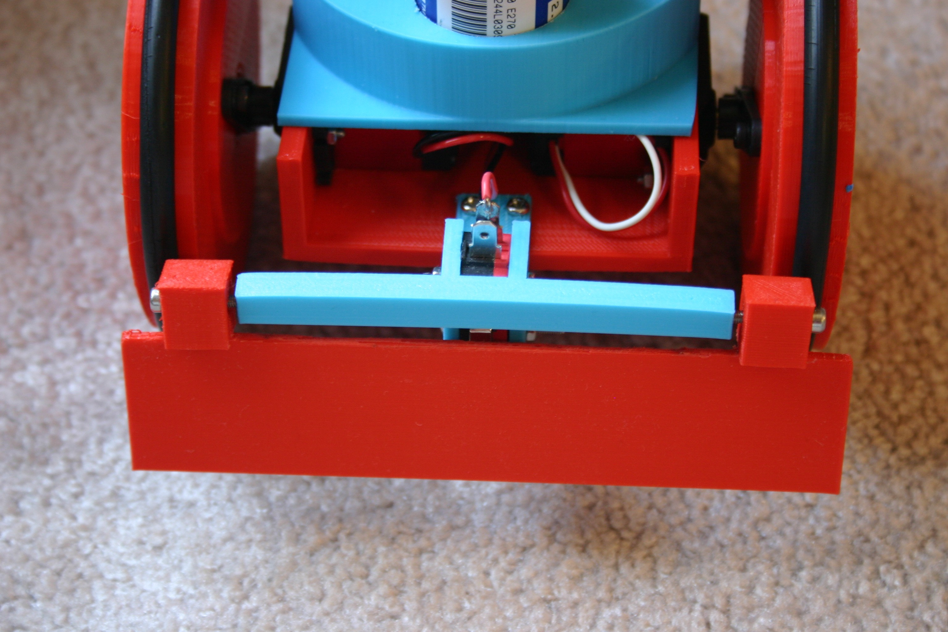
Add the "bump switch blade" to the lever switch bracket using 3mm screws. The blade should move very freely.
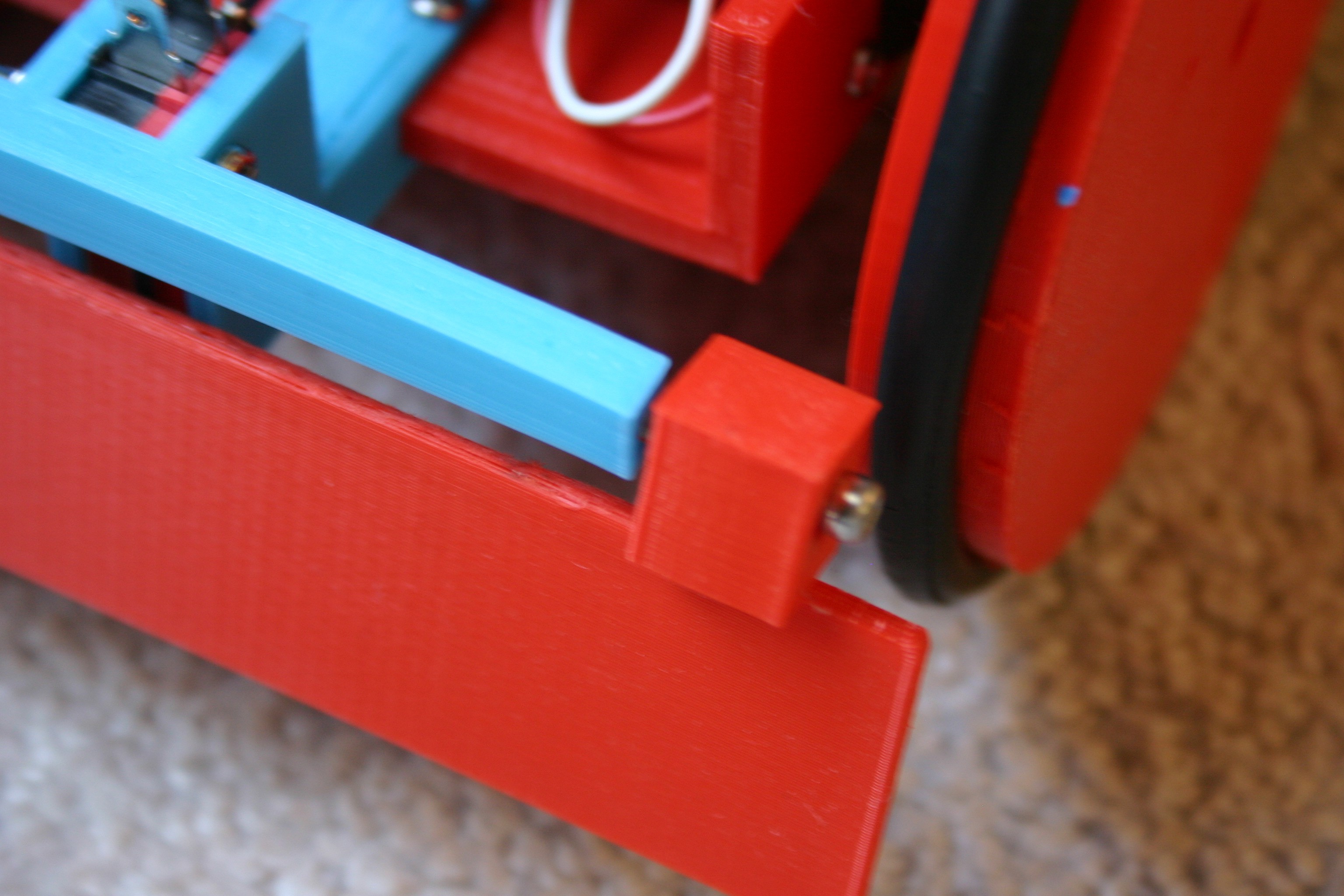
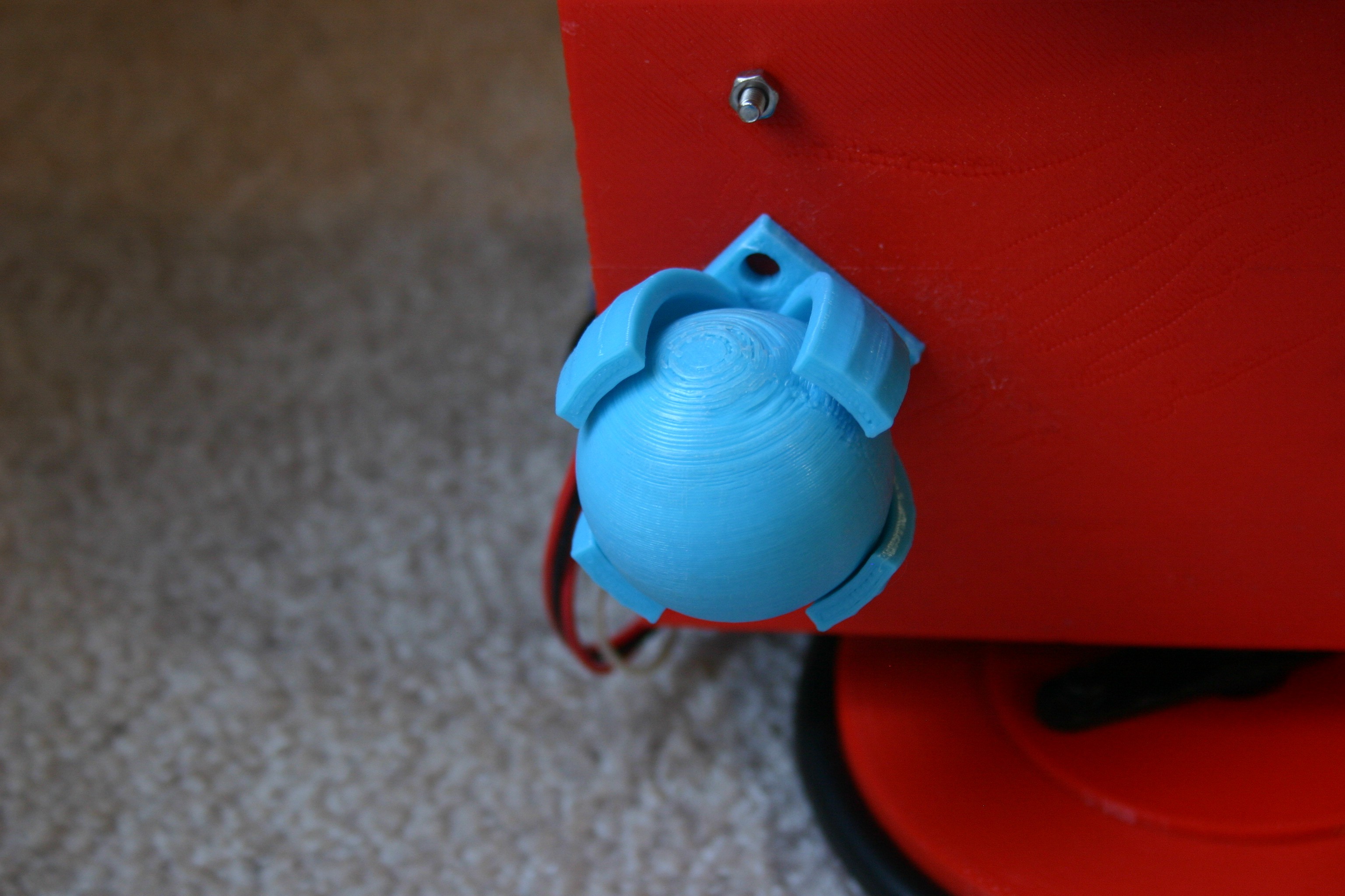
Secure the motors to the robot body (3mm screws). Add the wheels to the motor shaft (using the servo horn screw). Attach the capacitor holder to the robot body using screws. Attach the caster ball holder to the robot body using screws.
Insert the caster ball.
Set the output voltage for the converter to about 8 volts. Program the Arduino, charge the capacitors and she's ready to run.
Discussions
Become a Hackaday.io Member
Create an account to leave a comment. Already have an account? Log In.