 Tim Wilkinson
I'm continuing to experiment with detecting external forces acting on the robot joint, something that seems fundamental to any form of compliance. At the moment I'm interested in a situation where the joint is under no load (a robot leg taking a step) and as it come into contact with an obstacle (the ground) it responds to the external force to "soften the blow" rather than remaining rigid.
But because everything in the system is noisy, doing this with confidence is something I'm finding challenging.
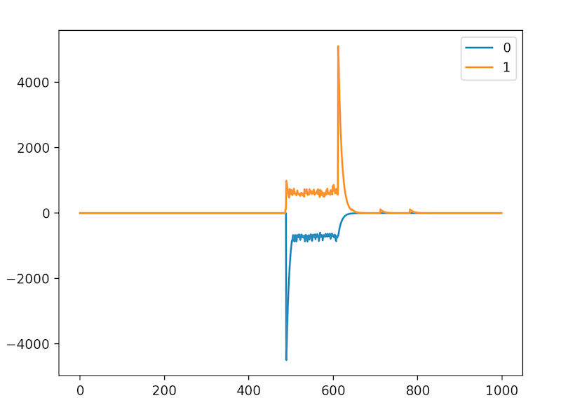
The graph above shows the minimum and maximum error (with decay) of a moving joint between the time when it receives an external force (which triggers movement) and comes to a stop (after a fixed period of time). Ignoring the start and end, the error is quite large and bounces around a fair bit due to the friction in the joint being non-uniform, errors in estimating joint velocity, and the ODrive doing its best to keep the velocity at a set point.
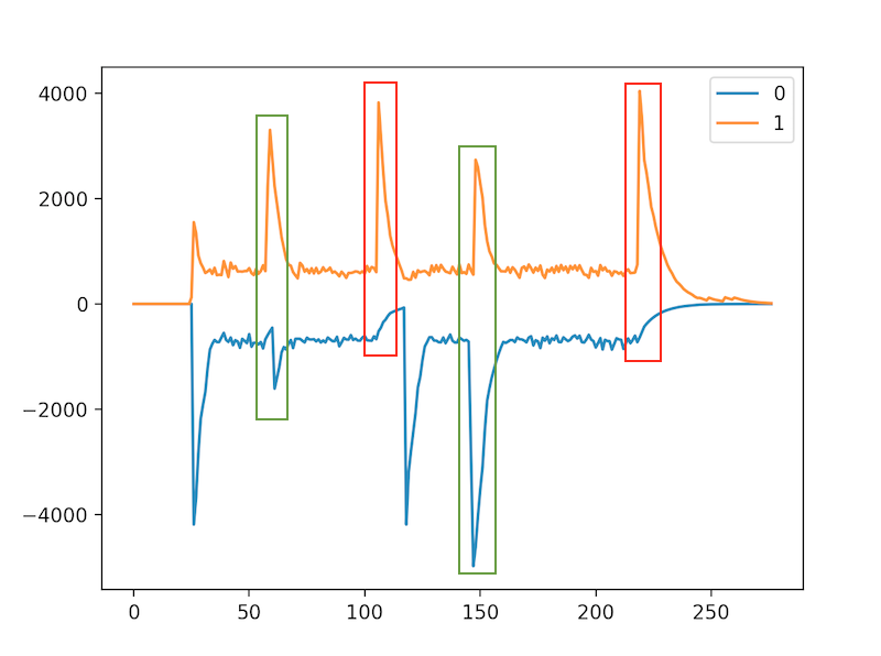
Here's another graph of the joint errors. This one contains more interesting events.
The red boxes highlight the points where the joint stops moving (without any external force) while the green boxes are points where an external force is applied to the moving joint. The first green box is for an anti-clockwise impulse, while the second green box is for a clockwise impulse. Note how, when an external force is applied, the error peak on one graph marginally proceeds the error on the other graph. This differs from the red boxes (where the joint comes to a stop without an external force) where the error only peaks on one graph. I think, maybe, that the way the errors changes might be a reliable way to detect, and respond to, an external force?
Discussions
Become a Hackaday.io Member
Create an account to leave a comment. Already have an account? Log In.
Perhaps you could amplify this red - blue difference by a factor such as velocity or decceleration, to add more contrast between a start event and a stop event.
Are you sure? yes | no