David Troetschel
-
Preliminary Optical Tests
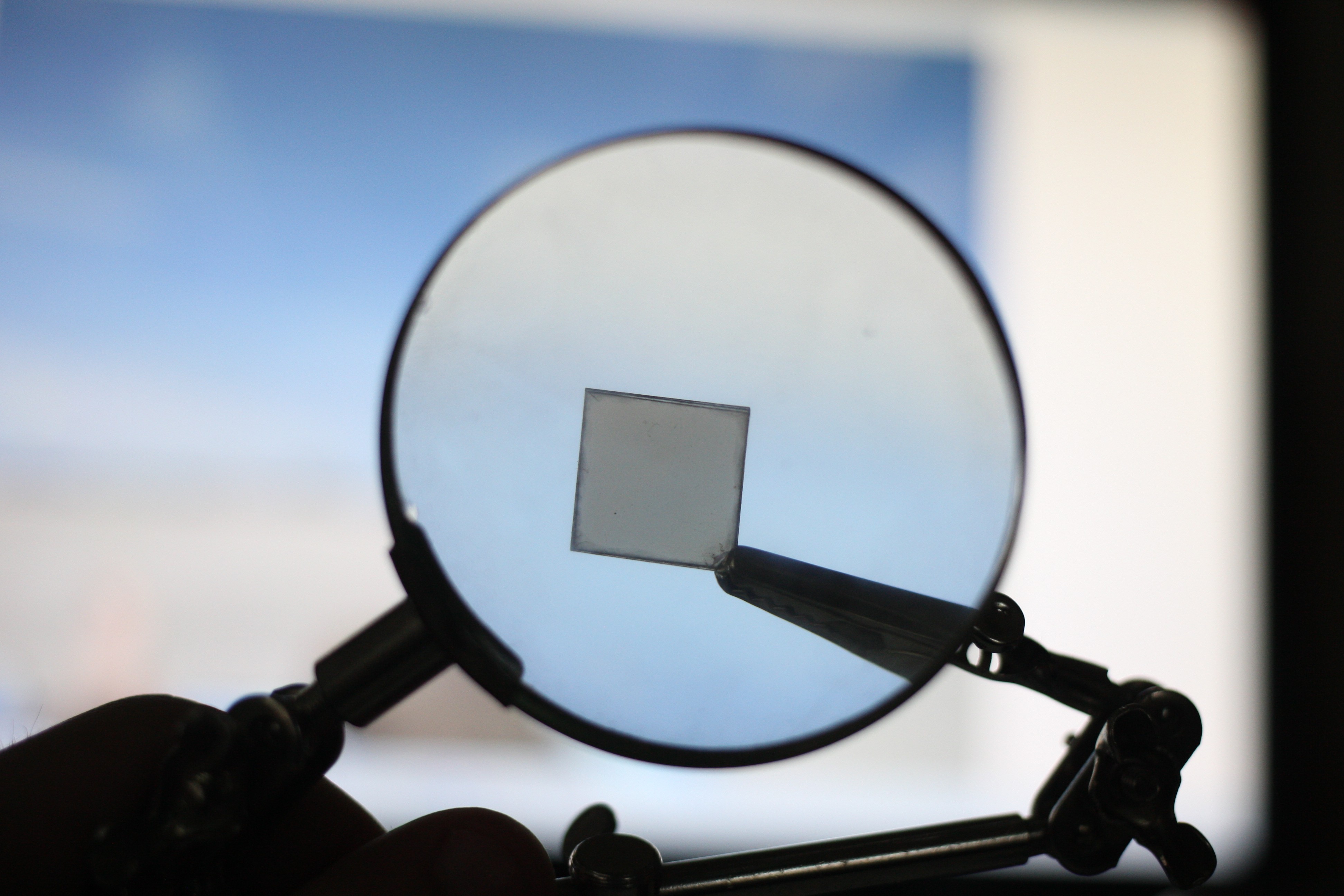
06/06/2019 at 22:51 • 0 commentsI conducted a brief optical experiment where we focused an led light from a cell phone through a magnifier and onto the mica sample. We observed the scattered light upon the wall afterwards. We panned the light source over the edge and across starting from the apparent left of the following images.
![]()
No conclusion is meant to be drawn from this information.
![]()
![]()
Looking into this more we're not sure if the coloration is from the mica or an interaction with the magnifier.
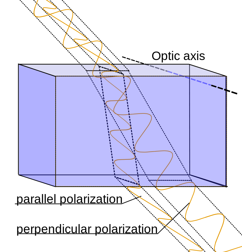
The greater investigation is into Birefringence.
![]()
To research more into this I ordered some polarized films which should arrive shortly. That deducts around $10 from the budget.
----
I have not done a comparison of apparent optical clarity and transmission yet. I think I will just make a light source and then a testing rig to take photos through with progressive layers. There should be a way to measure the change in brightness then. I will likely have to have the lens right upon the sample to eliminate over-bleed and lock in speed, etc. for a fair comparison.
I also started doing some snooping around for nose bridge cushions, most of which are silicone. (so I could make a custom mold...) Stick on ones seem very inexpensive and like the way to go, but I'll see where the next couple designs go.
-
Frame Outsourcing
06/04/2019 at 17:08 • 0 commentsBefore I get too far designing the frame "my way" (how I intuitively think they should be constructed) I looked deeper into how they are manufactured currently.
While I could adapt a design to fit the process shown, I'm not really interested in a bent wire frame. It also definitely doesn't make sense for 5-45 pairs initially.
I still think that investment casting of a solid frame is the way to go.
I'm curious to see how Gentle Monster makes their frames, I'm a big fan.
If I am casting around the lenses I need to consider metal temperature affects on the mica, going by the Wikipedia section "It has superior electrical properties as an insulator and as a dielectric, and can support an electrostatic field while dissipating minimal energy in the form of heat; it can be split very thin (0.025 to 0.125 millimeters or thinner) while maintaining its electrical properties, has a high dielectric breakdown, is thermally stable to 500 °C (932 °F), and is resistant to corona discharge. Muscovite, the principal mica used by the electrical industry, is used in capacitors that are ideal for high frequency and radio frequency. Phlogopite mica remains stable at higher temperatures (to 900 °C (1,650 °F)) and is used in applications in which a combination of high-heat stability and electrical properties is required. Muscovite and phlogopite are used in sheet and ground forms.[11]"
Anyways, looking at common melting temperatures and knowing that the design needs to stay sub 1600F a good number of metals are not going to happen.
https://www.engineeringtoolbox.com/melting-temperature-metals-d_860.html
Looking through this list the remaining possible metals could be:
Aluminum, Magnesium, Plutonium, Tin and Zinc.
I am curious what will happen to the mica if it goes above its melting point and if it can cool and reform or does it change? If the transition creeps maybe this will even be a benefit? I think that the first designs will be safe materials and then as funding allows move to other risky materials.
-
Embedded casting and prototype
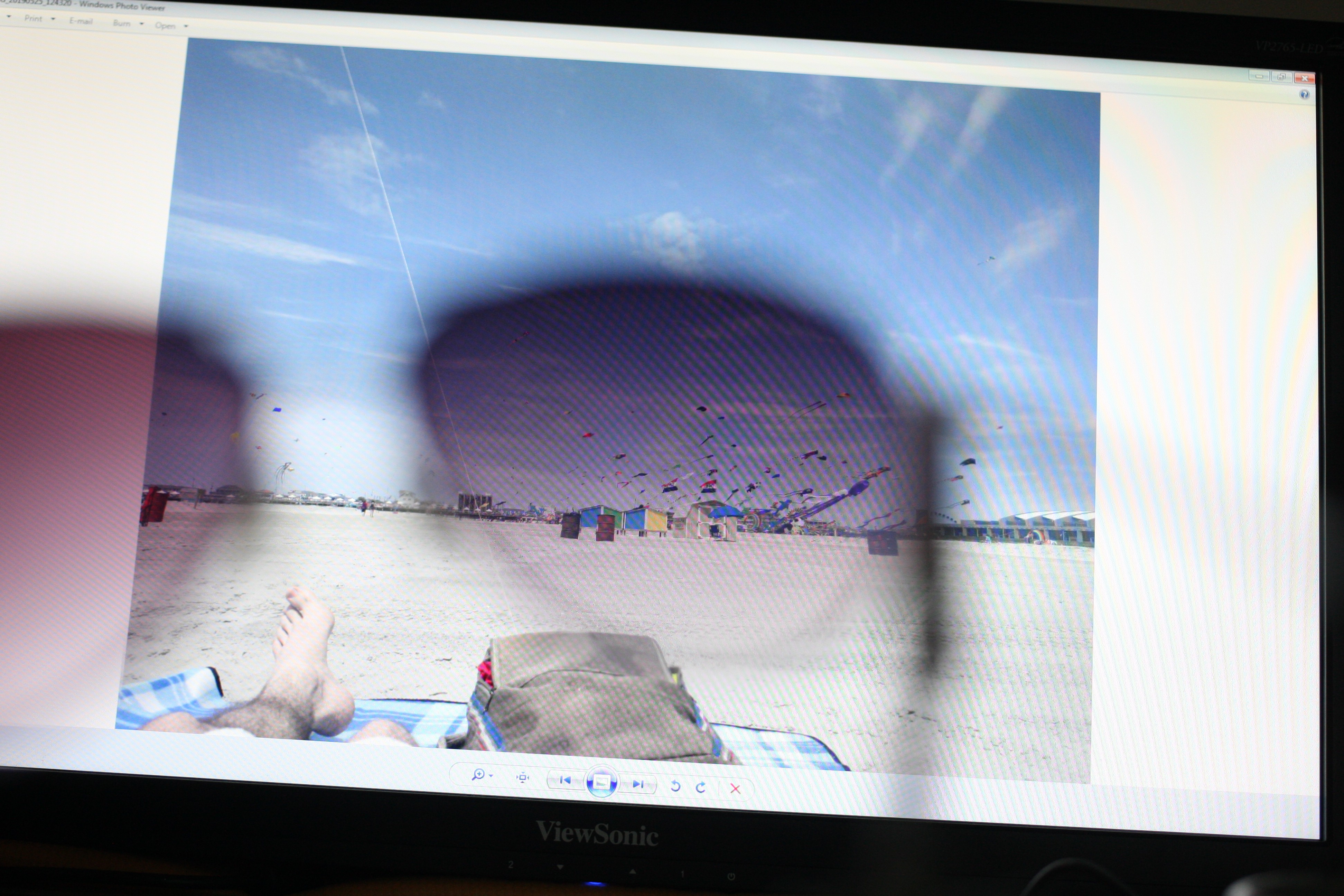
06/04/2019 at 00:53 • 0 commentsSince receiving the V2 grade mica I've been trying to do a comparison study of visible light transmission. My trials so far have been inconclusive but the V1 is certainly higher quality, no defects.
I tried comparing single, double and triple layers to a pair of stock sunglasses using a monitor as a back-drop. The images didn't come out very well.
![]()
![]()
The other images communicated almost nothing, not sure how to go about it a better way... Maybe next time I'm visiting my old campus I'll ask around, I need to talk to one of the engineering professors anyways to return a book (oops!)
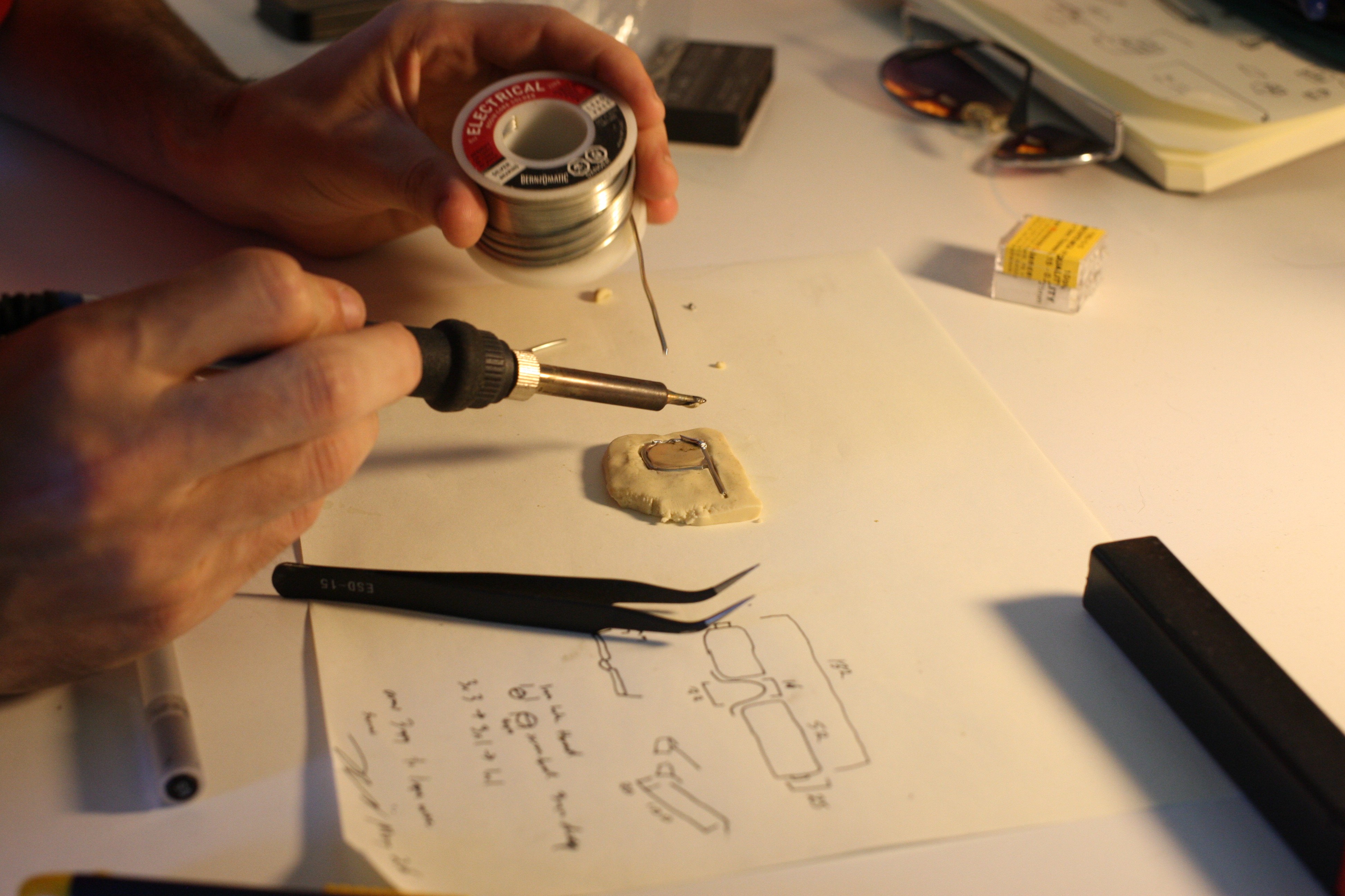
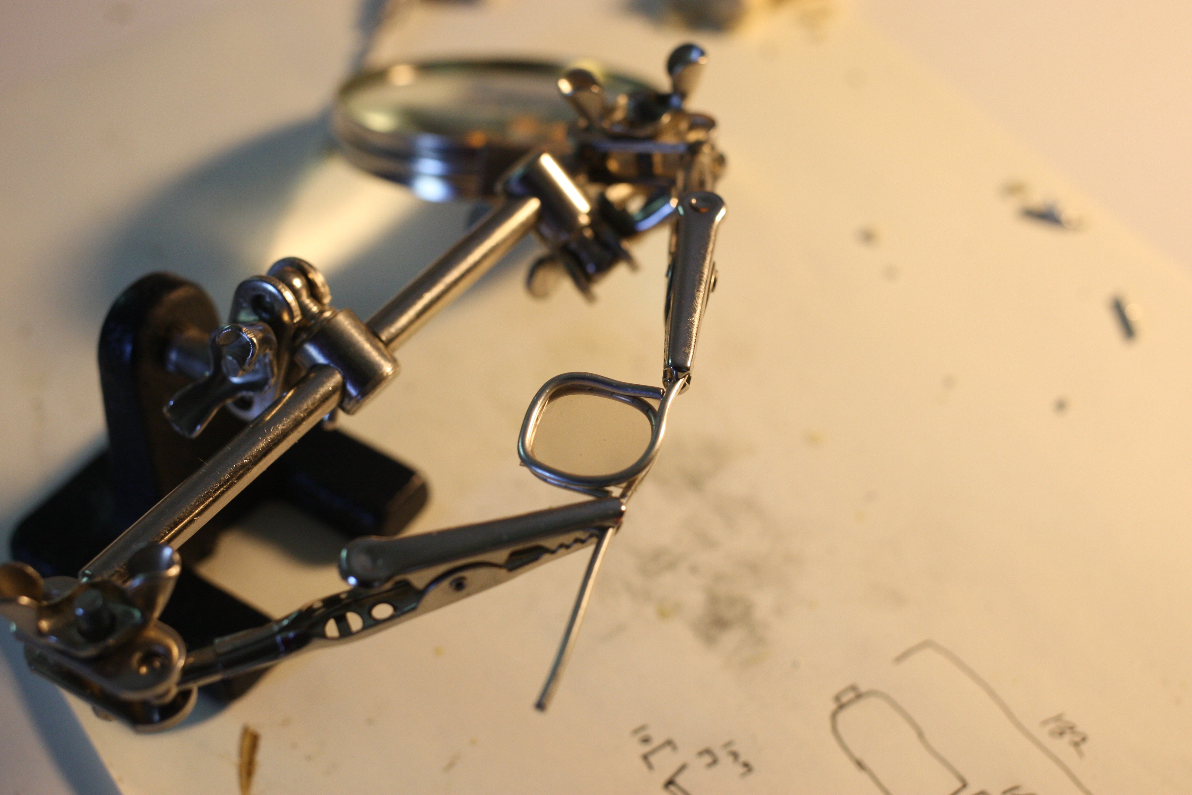
One of Micas unique properties is its heat resistance, so much so that there didn't seem like there would be any problem using solder directly on it, potentially a metal with a much higher melting point too. This could be used to make the frames more unique.
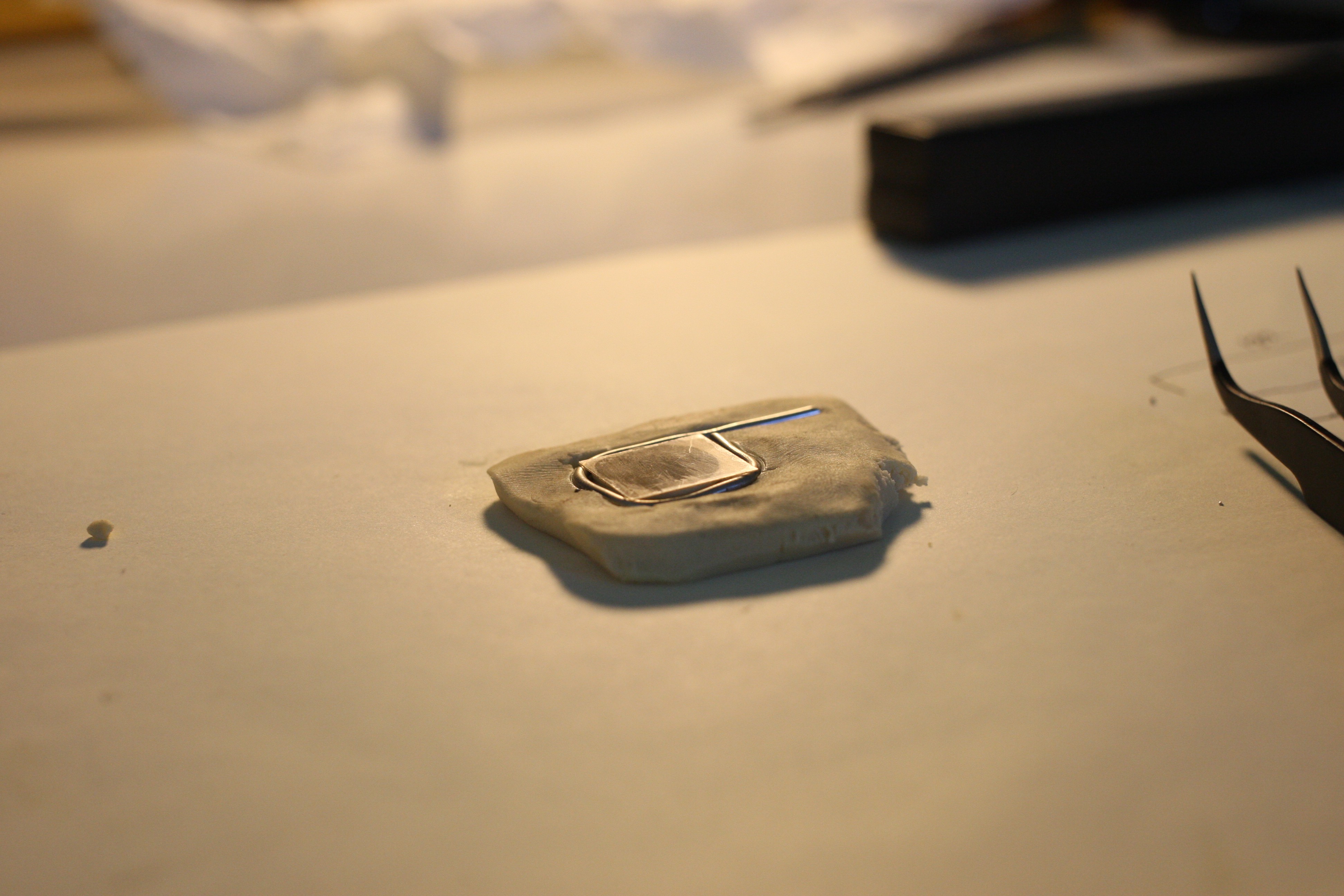
So I wanted to try embedding a lens in solder.
![]()
![]()
Okay; modelling clay and solder do not mix. Ended up contaminating the lens and scratching it up trying to clean before I tried alcohol. The alcohol ended up cleaning off the flux and gross stuff easily.
![]()
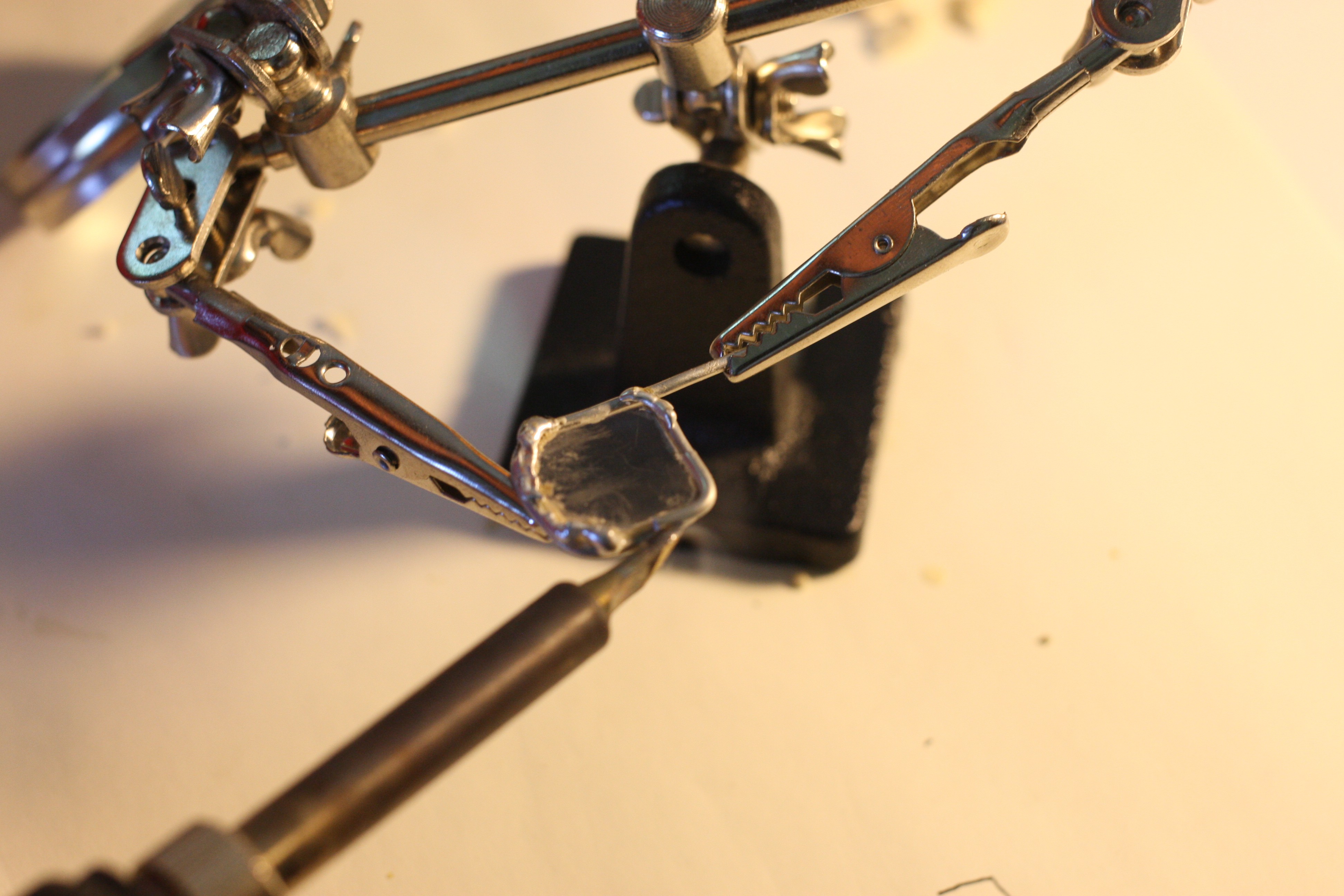
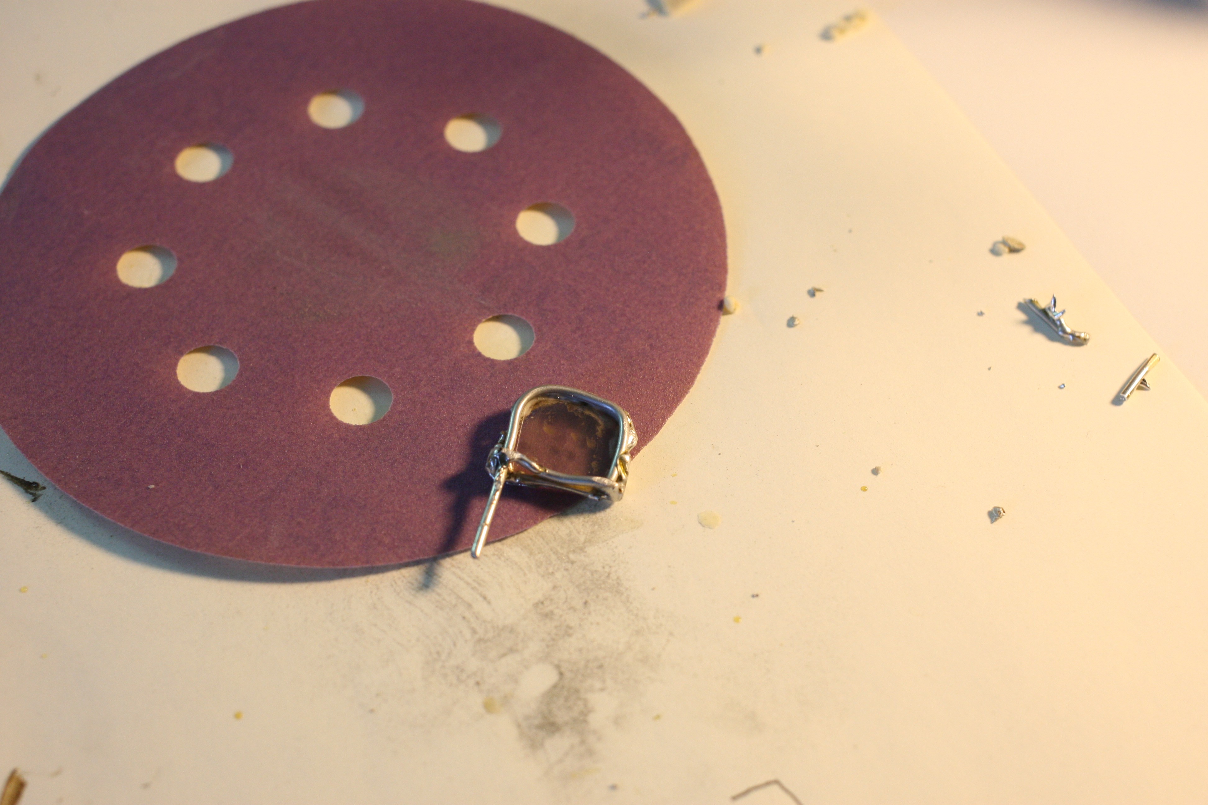
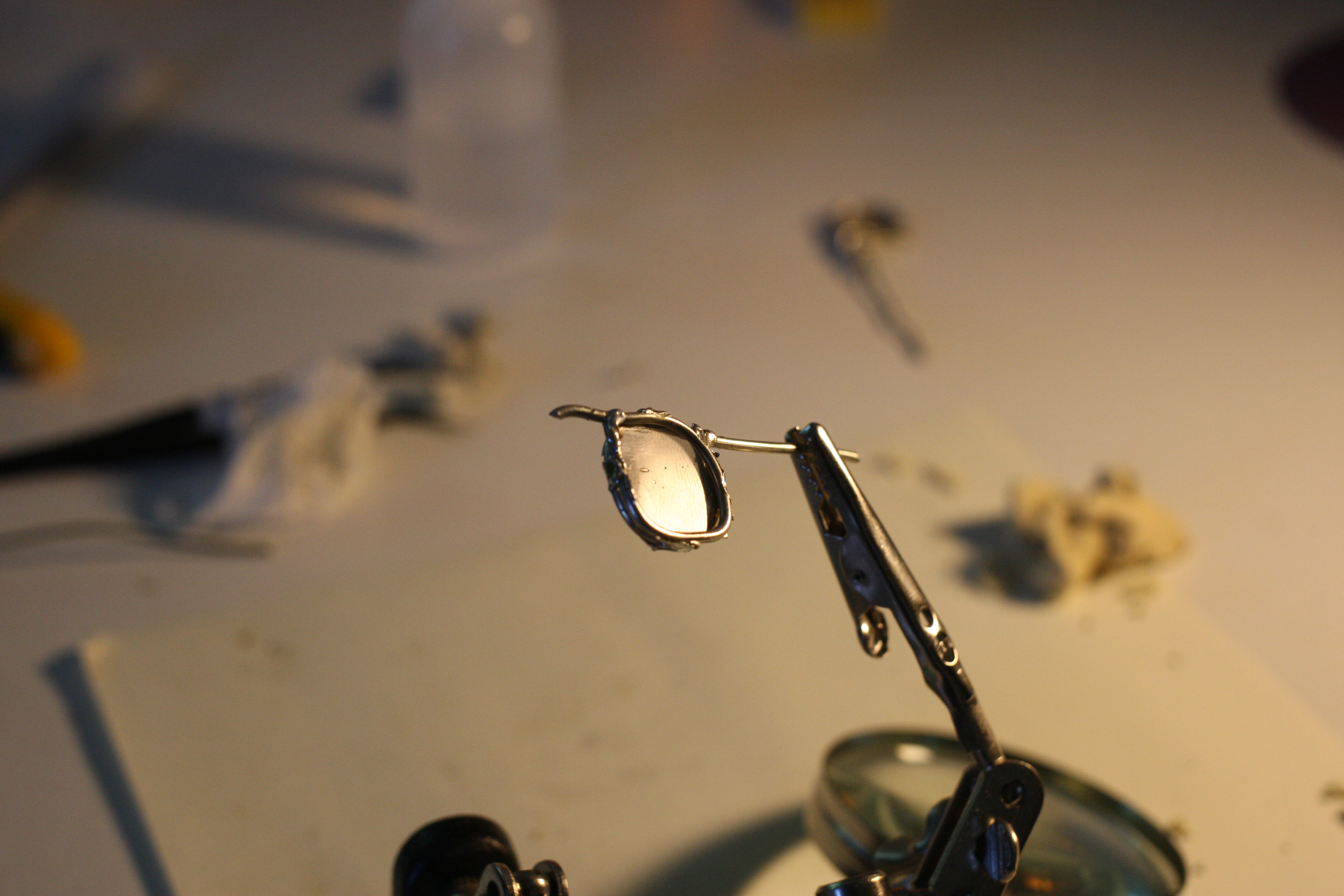
Using a single line of solder was not the best idea, super fragile. I ended up having to glob a lot on to get it stable and even completely botched a quarter. So I folded over a segment and clamp jointed before soldering.
![]()
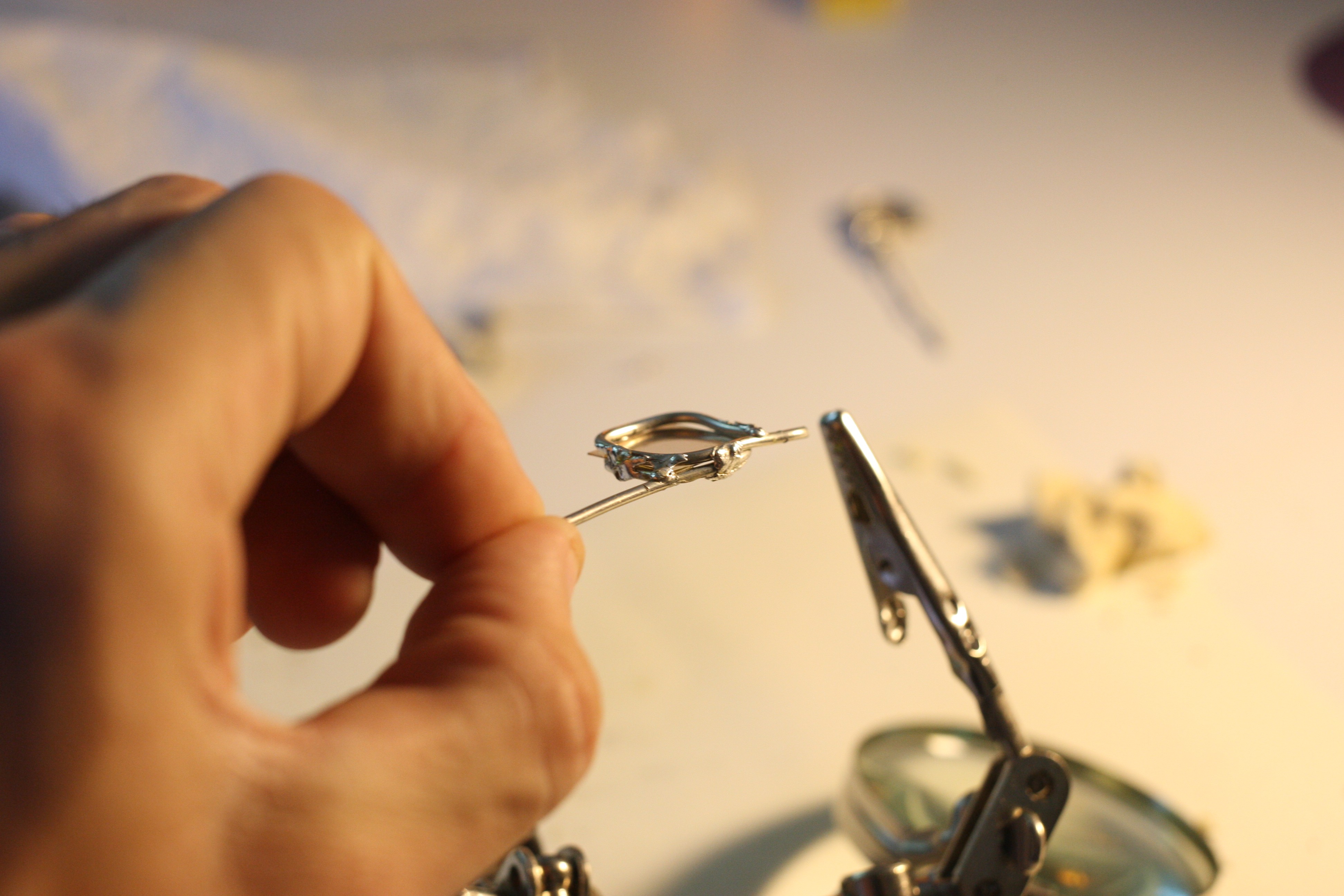
After a little cleaning I decided to go ahead and make a second assembly, this time with two loops clamping onto the lens.
![]()
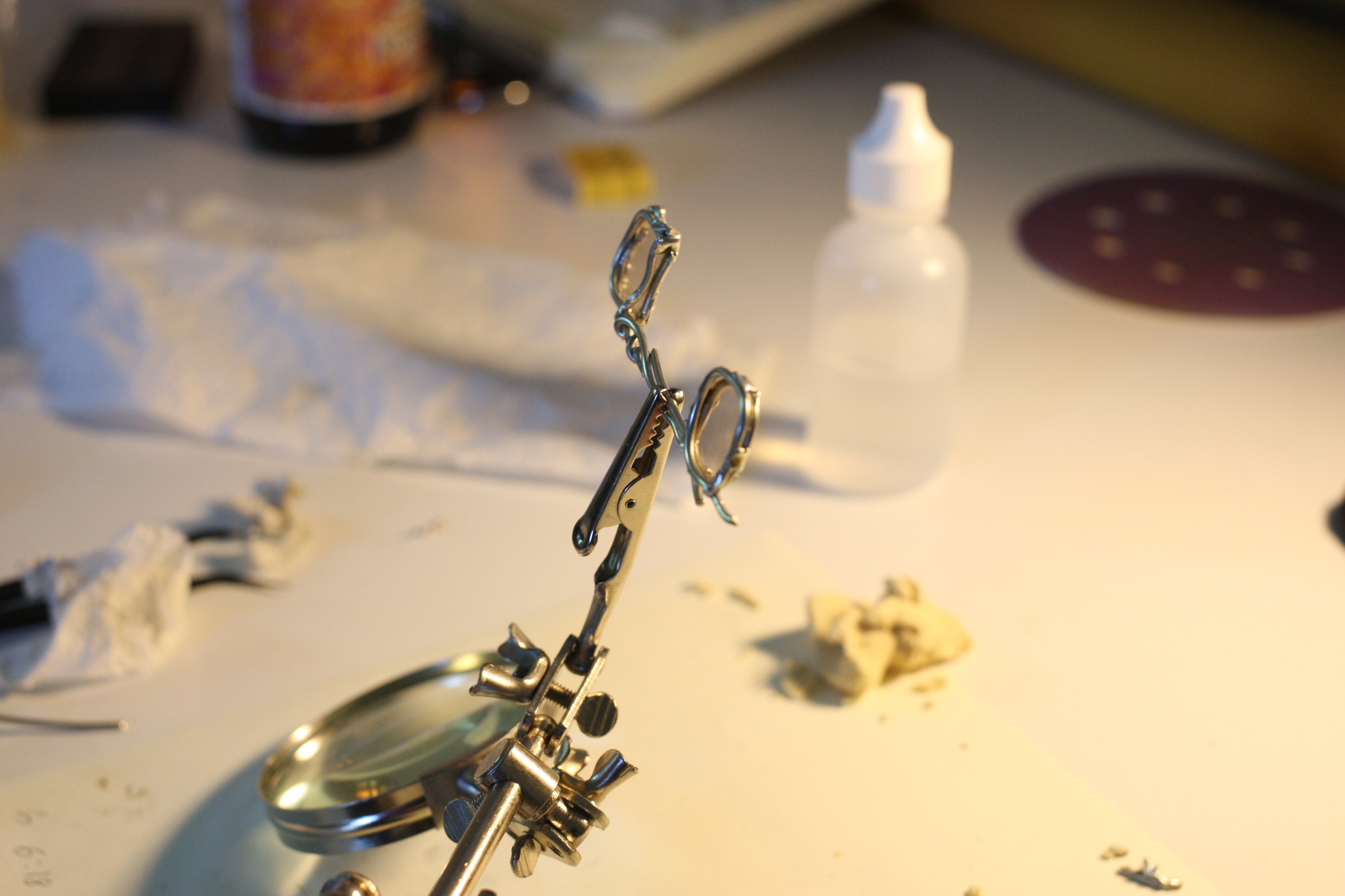
I then sealed all four sides.
![]()
![]()
After both lenses were finished I figured out the spacing as best I could and then joined them.
![]()
Then I made a crude nose bridge and added arms.
![]()
Alignment is definitely off, but tolerable. Orientation is also off on one lens. Considering the size of these test lenses I'm actually surprised how easy it is to look through them. Since the lenses are single sheet stacks there are no interesting visuals, only a slight fade and blur.
![]()
![]()
![]()
All in all, not too bad for a first prototype.
-
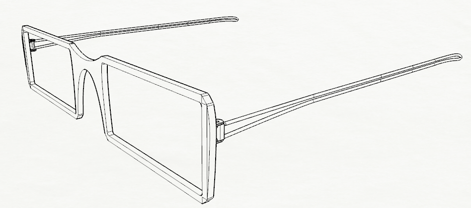
Second Frame
05/26/2019 at 21:45 • 0 commentsI realized that I was working in the wrong units for the wire arms, they were also too short to be usable. Scaling them up wasn't a big deal and they still look "right."
From there I also made a new frame, it will have a channel cut to accept the mica. I haven't modeled the nose bridge, which could really use a redesign and I will also need to integrate the arm pivots into the frame before this is really usable. Overall it seems possible though.
![]()
![]()
Some details like the arm screw size and inset will need to change.
The actual look of the frame could use some help too, but this is progress.
The frame is 2mm thick as shown. Arms are ~120mm long.
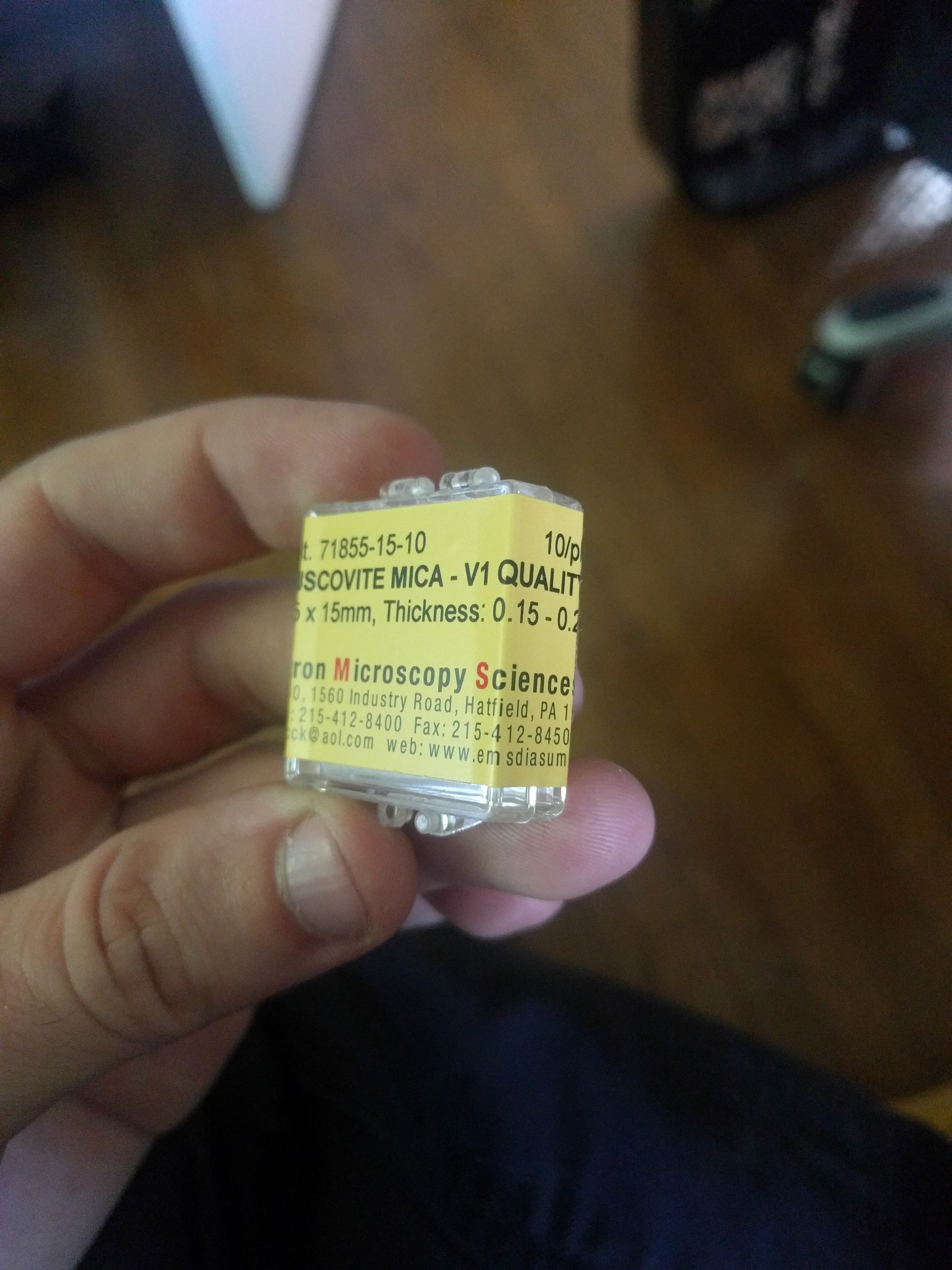
I also received the V1 Mica samples, haven't tried cutting or flex tests yet.
![]()
Yay for local businesses! Also note that I seriously blanked on the size; moral of the story, don't order supplies late at night. The upside is that I can do lots of tests now. This means that my *estimates* on how much the lenses will cost were pretty.... VERY off.
The lenses in the above model are 52x25mm very small for "sunglasses" The largest I can order locally are 50x75mm at $60. This means if I make the lenses 50x25 and don't make a single mistake I will be able to make fifteen pairs. $4 a pair (for the lenses) sounds pretty good to me, and honestly... fifteen pairs sounds like a decent small run.
So then the real question becomes whether a single sheet is dark enough or whether they will need to be stacked. The most I can imagine stacking them is three layers deep, for a combined thickness of around .6mm. That would drive costs of the lens assembly to $12-15 a pair, and only five frames. Assuming I choose this course of action it would allow for a budget of around $100 to produce each frame, which sounds doable.
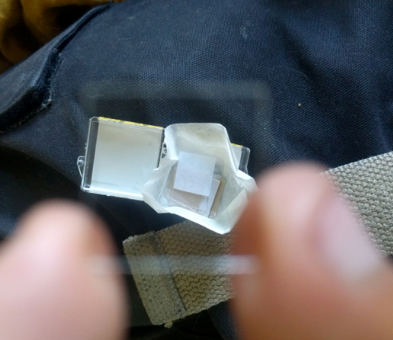
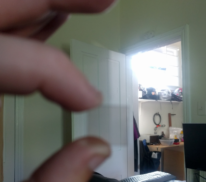
Anyways, here is a single sample.
![]()
![]()
Better photos will follow when I do testing.
-
Wire arm design
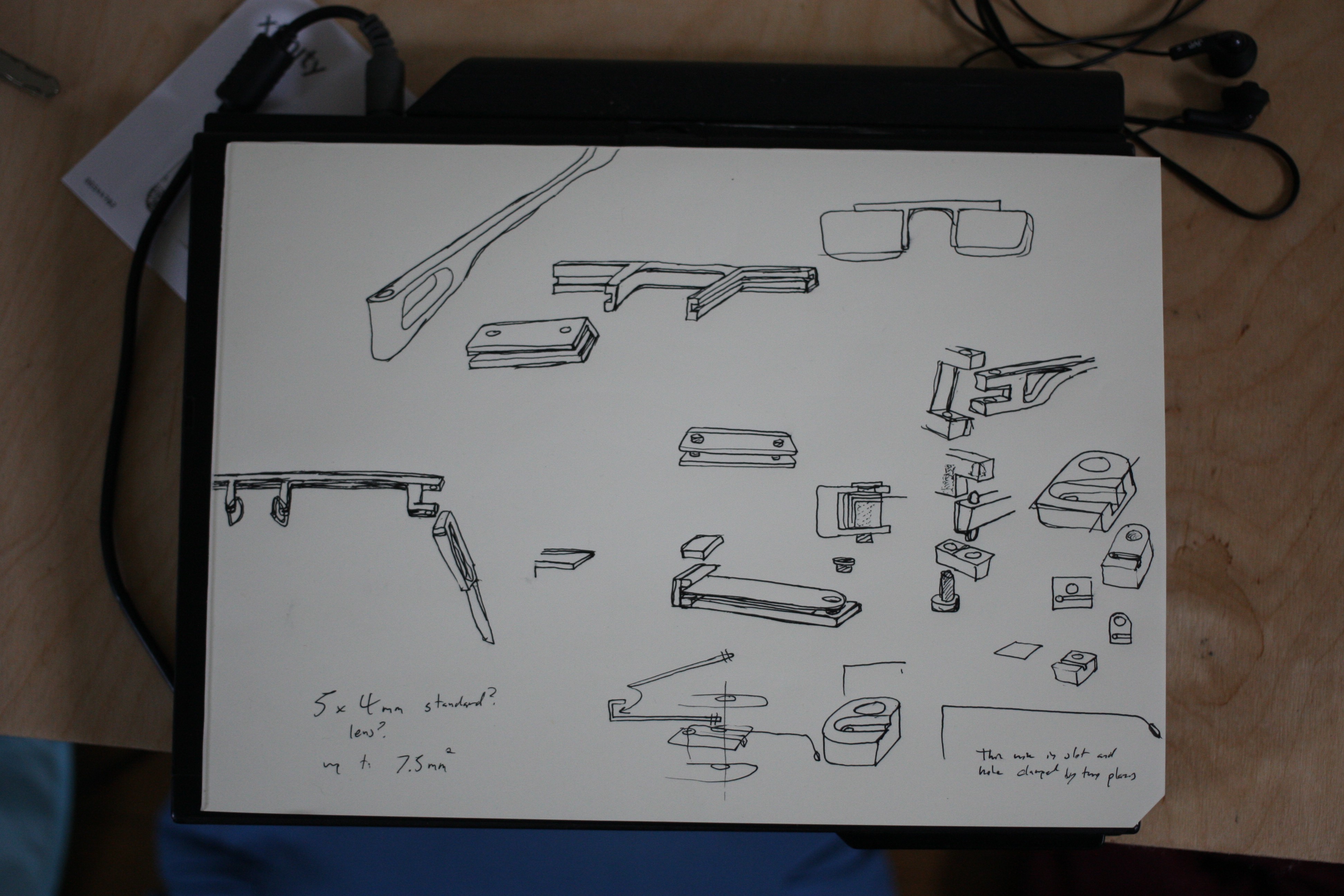
05/23/2019 at 17:32 • 0 commentsI started drawing out some ideas of how to trap the lens in a frame and came up with a couple ideas.
![]()
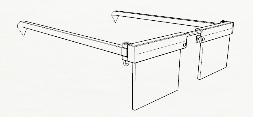
I jumped into modelling a pair using a leaf spring like retaining mechanism since one of the tricky aspects of this project will be allowing for variations in lens thickness.
![]()
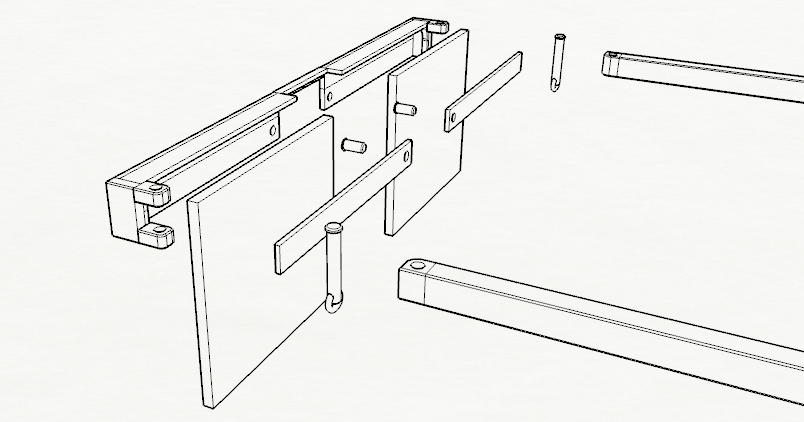
An exploded view
![]()
![]()
Not bad for a first draft.
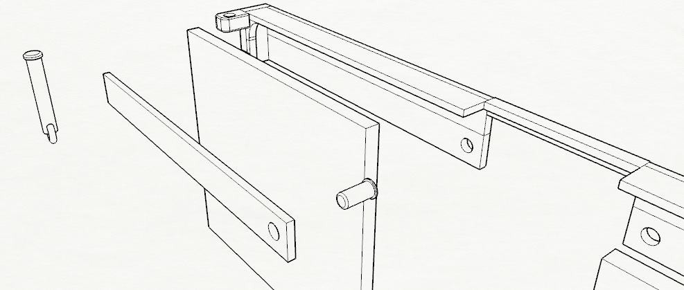
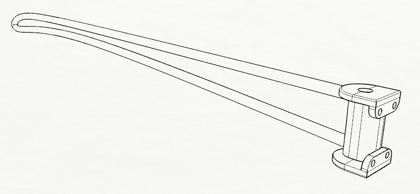
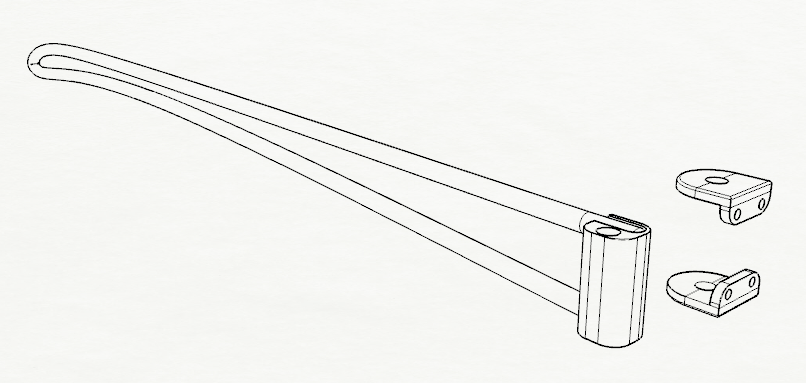
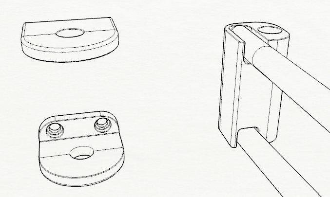
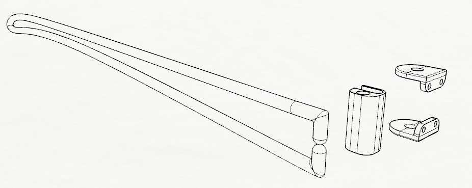
I also came up with a bent wire arm design where a single piece of wire fits into guide channels and then enclosed in the hinge mechanism to hold the assembly together. This would allow for easy sizing changes so I'm pretty keen on this. I will definitely have to go back later with real wire dimensions and such, so what I'm showing is pretty accurate, but still just an approximation. Hopefully it makes sense. The rotational post is off-center to allow for the folding action to be one way. I think the support (clamping structure?) is too complex and frankly.... too big. Even though it is rather small. Guess I'll have to see how it fits with a frame or integrate the supports into the frame itself.
![]()
![]()
![]()
![]()
For reference; the channel block as shown is 1mm tall, wire is .1mm diameter.
-
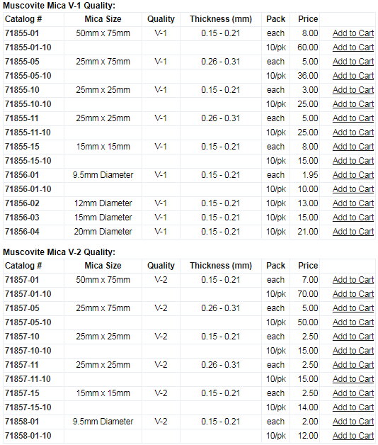
Purchasing Mica
05/23/2019 at 16:44 • 0 commentsI ended up buying 10 sheets of both V-1 and V-2 Mica via https://www.emsdiasum.com/microscopy/products/preparation/mica.aspx
Measuring a couple of pairs of glasses around our house it seems most lenses are around 5x4-5x5mm. Assuming there is no waste this means that about 45 (WHOA!) pairs could be made.... But lets not get too excited, I'll wait until I actually get the mica.
![]()
The total price of the order was around $29.
Thankfully the supplier is close by, so should be here soon.
-
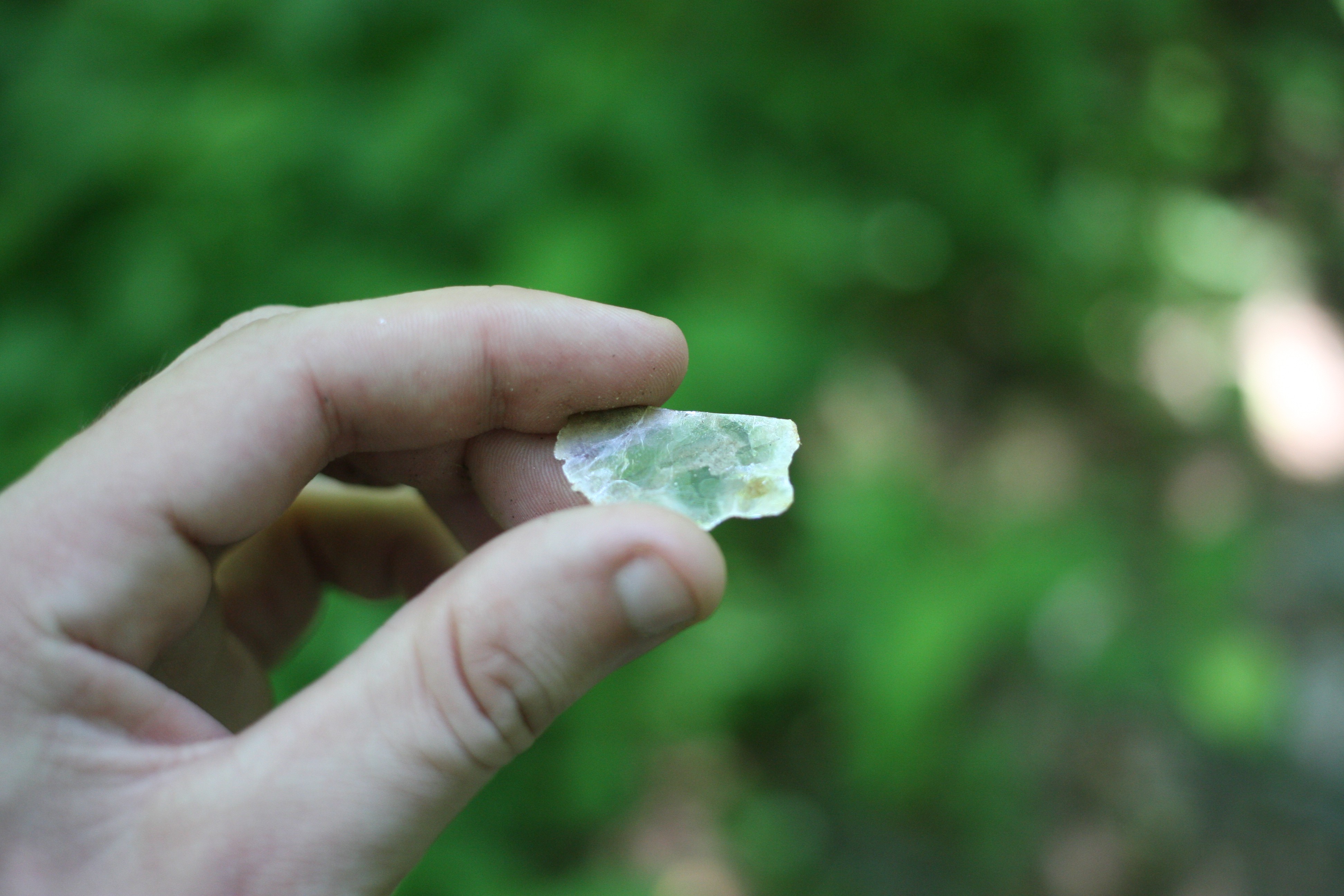
Mica hunting and shopping
05/23/2019 at 01:24 • 0 commentsWhile on a hike today I came across a nice small sheet of mica. I often joke around with my partner when we go for walks in the park that I'm going to make another pair "one of these days..." But today I was alone and so started actually brainstorming.
A scene as through the Canon 1D Mark III with a 40mm macro.
![]()
And the same scene through the mica (very poor quality mica.)
![]()
![]()
I saved this sample to compare to later examples.