 agp.cooper
The Mathematical Model
I am not going to go into the mathematics. It is high school maths (Cosine rule and solutions to quadratic equations). You just need to send time (i.e. a week) working through it.
What is important is what it does:
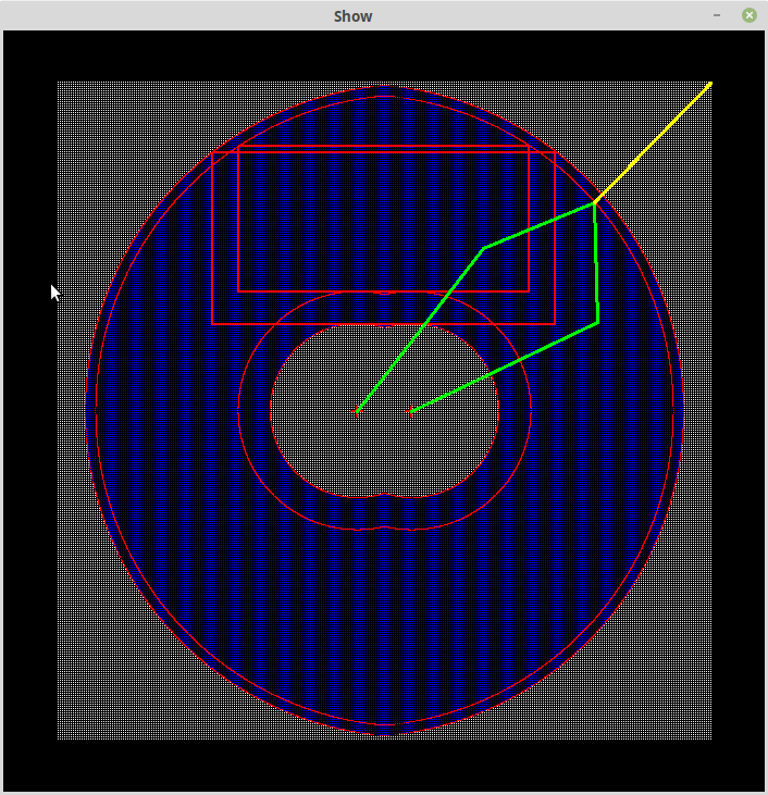
What you can see here is a test of the model:
- The white dots are the provided (test) coordinates, and the blue dots are the coordinates that were plottable by the machine (given the machine specifications).
- The red dots that outline of the blue dots are the machine physical limits.These red dots are a one to one transformations of the white dots.
- The large red rectangle is the largest 2:1 work area available for the given machine specification.
- The other red dots are for the soft constraint (i.e. the 30 to 150 degree far arm angle limit). These enclose work areas that have a degree of rigidity. Well at least if the 30 degree angle constraint is a good number to use.
- The yellow line shows the movement of the extreme top right point to the soft constraint boundary, and the arm positions (green). Demonstrating that the mathematics appears to be working.
- The only thing missing from this model test are the left and right elbow positions (next time!).
What Next?
How much force can be transmitted through the arms using a 30-150 degree far arm limit? Should I use a 45 to 135 degree far arm limit?
What arm lengths should I use to optimise the soft constraint work area?
What driver motor spacing is best? The closer the spacing, the more work area, but what about force transmission?
Why Truncate Unplottable Points?
Basically, he motion planner needs the transformed constrained points to navigate around these infeasible areas:
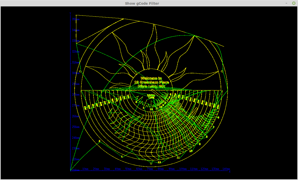
Consider the above drawing, although I don't have to plot the constrained points at the top of the page, but I do need to move the machine head via those points towards to first plottable point.
Alan
Discussions
Become a Hackaday.io Member
Create an account to leave a comment. Already have an account? Log In.