 Alessandro Sottocornola
In order to make the atmospheric discharges sensor more easily usable, i have made a breakout board containing the AS3935 integrated supply. The heart is clearly the IC, and i bring its power, the communication bus with external microcontroller circuits and the major control signals, to the outside. All the lines to connect externally or to be handled externally are brought to a line of pads with 2.54 mm gap on one side, to which we can apply a pinstrip. Data connection with the external world is serial, using an I²C-Bus or SPI bus; in the last case we will make use of the lines:
- MISO (Master Input Slave Output) which is to breakout boards output used to send data related to detected lightnings to Arduino;
- MOSI (Master Output Slave Input) which is the data output of Arduino used to communicate setting message or confirmation message to the breakout board;
- CS (Chip Select) which is the line of Arduino enabling the breakout board to interact on the SPI bus; CS is useful because several devices can use the SPI and in order to avoid data collegians we need every communication session to enable just one device per time.
- SCL (clock) corresponding to the signal synchronizing bus communication.
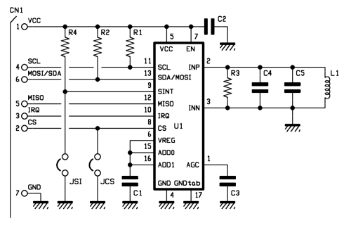
Note that pin 8 of the AS3935, i.e. the CS is kept at logic level high from its internal pull-up resistor if not specified otherwise, but it can be forced to logic zero by the JCS jumper where external management is not needed. For what concerns serial communication mode, this can be selected on the breakout board using the second jumper, labeled SI, intervening on pin 9 (Select Interface); the integrated AS3935 integrated works:
- in SPI mode if being at 9 is at logic zero;
- in I²C mode if Select Interface is at VDD.
In my application i chose the first option, so you can see the jumper has been closed.
I have pin IRQ (10), brought to terminal 3 of the CN1 connector, which communicates the microcontroller when IRQ is an output that AS3935 Brinks logic level high when a lightning is detected and the corresponding value is written in one of the internal registers (REG0x03[3:0]).
The input stage, which is the stage that allows me to detect the radioelectric disturbance corresponding to the lightning; this is related to pins 2 and 3, which are the radio-receiver input of the integrated circuit, which requires an anti-resonant circuit to the input in order to tune a certain bandwidth and exclude low-frequency disturbances which are not relevant to the purpose.
Application
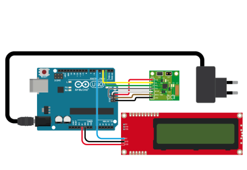
The project i am proposing is essentially made of three elements: lightning detector, available on the breakup board, an Arduino Uno board, which duty is to analyze the signal provided by the sensor, process it and show on serial LCD display (which is the third element of the circuit) the information extracted, i.e. the number of electric discharges detected that can be considered “spawn” of lightning along with estimated distance.
Everything must be connected as we can see in the wiring diagram visible in these pages, where the sensor breakout board interfaces with Arduino through the ISCP connector, since the latter carries the complete, 4-line SPI bus.
In order to manage the serial display, we use a software serial, emulated thanks to the SoftwareSerial.h library, which allows you to free the hardware serial for possible applications that need it. The sensor breakout board is connected, as mentioned, through an SPI bus, from which it receives all the settings and communicates data regarding lightning detection; the onboard chip is enough on itself to measure intensity and detect the course of the electrical discharges detected by the coil mounted on the breakout board, therefore the data provided to not require any special processing by Arduino.
The connection with the breakout board takes advantage of the SPI bus lines reported on the ICSP connector; then we have GND (ground) and Vcc (connected to +5V) used by the board to take power from...
Read more »


I am very interested in the project but when compiling the program the following error appears
Arduino: 1.6.9 (Windows 10), Placa:"Arduino Uno"
sketch_dec15a:3: error: prototype for 'AS3935::AS3935(byte (*)(byte), int, int)' does not match any in class 'AS3935'
AS3935::AS3935(byte (*SPItransfer)(byte),int csPin, int irq)
^~~~~~
In file included from C:\Users\pedro\AppData\Local\Temp\arduino_modified_sketch_455238\sketch_dec15a.ino:1:0:
C:\Users\pedro\OneDrive\Documentos\Arduino\libraries\AS3935\src/AS3935.h:9:7: error: candidates are: AS3935::AS3935(AS3935&&)
class AS3935 {
^~~~~~
C:\Users\pedro\OneDrive\Documentos\Arduino\libraries\AS3935\src/AS3935.h:9:7: error: AS3935::AS3935(const AS3935&)
C:\Users\pedro\OneDrive\Documentos\Arduino\libraries\AS3935\src/AS3935.h:43:2: error: AS3935::AS3935()
AS3935(void);
^~~~~~
sketch_dec15a:13: error: no 'byte AS3935::_SPITransfer2(byte, byte)' member function declared in class 'AS3935'
byte AS3935::_SPITransfer2(byte high, byte low)
^
sketch_dec15a:22: error: no 'byte AS3935::_rawRegisterRead(byte)' member function declared in class 'AS3935'
byte AS3935::_rawRegisterRead(byte reg)
^
sketch_dec15a:27: error: no 'byte AS3935::_ffsz(byte)' member function declared in class 'AS3935'
byte AS3935::_ffsz(byte mask)
^
sketch_dec15a:36: error: no 'void AS3935::registerWrite(byte, byte, byte)' member function declared in class 'AS3935'
void AS3935::registerWrite(byte reg, byte mask, byte data)
^
sketch_dec15a:47: error: no 'byte AS3935::registerRead(byte, byte)' member function declared in class 'AS3935'
byte AS3935::registerRead(byte reg, byte mask)
^
sketch_dec15a:56: error: no 'void AS3935::reset()' member function declared in class 'AS3935'
void AS3935::reset()
^
C:\Users\pedro\AppData\Local\Temp\arduino_modified_sketch_455238\sketch_dec15a.ino: In member function 'bool AS3935::calibrate()':
sketch_dec15a:64: error: 'INT_MAX' was not declared in this scope
int target = 3125, currentcount = 0, bestdiff = INT_MAX, currdiff = 0;
^~~~~~~
C:\Users\pedro\AppData\Local\Temp\arduino_modified_sketch_455238\sketch_dec15a.ino:64:51: note: suggested alternative: 'INT8_MAX'
int target = 3125, currentcount = 0, bestdiff = INT_MAX, currdiff = 0;
^~~~~~~
INT8_MAX
sketch_dec15a:73: error: 'AS3935_LCO_FDIV' was not declared in this scope
registerWrite(AS3935_LCO_FDIV,0);
^~~~~~~~~~~~~~~
sketch_dec15a:73: error: 'registerWrite' was not declared in this scope
registerWrite(AS3935_LCO_FDIV,0);
^~~~~~~~~~~~~
C:\Users\pedro\AppData\Local\Temp\arduino_modified_sketch_455238\sketch_dec15a.ino:73:3: note: suggested alternative: 'digitalWrite'
registerWrite(AS3935_LCO_FDIV,0);
^~~~~~~~~~~~~
digitalWrite
sketch_dec15a:74: error: 'AS3935_DISP_LCO' was not declared in this scope
registerWrite(AS3935_DISP_LCO,1);
^~~~~~~~~~~~~~~
sketch_dec15a:79: error: 'AS3935_TUN_CAP' was not declared in this scope
registerWrite(AS3935_TUN_CAP,currTune);
^~~~~~~~~~~~~~
C:\Users\pedro\AppData\Local\Temp\arduino_modified_sketch_455238\sketch_dec15a.ino:79:19: note: suggested alternative: 'AS3935_VERSION'
registerWrite(AS3935_TUN_CAP,currTune);
^~~~~~~~~~~~~~
AS3935_VERSION
sketch_dec15a:83: error: '_IRQPin' was not declared in this scope
prevIrq = digitalRead(_IRQPin);
^~~~~~~
sketch_dec15a:94: error: 'currdiff' was not declared in this scope
currdiff = target - currentcount;
^~~~~~~~
C:\Users\pedro\AppData\Local\Temp\arduino_modified_sketch_455238\sketch_dec15a.ino:94:5: note: suggested alternative: 'currIrq'
currdiff = target - currentcount;
^~~~~~~~
currIrq
sketch_dec15a:104: error: 'AS3935_TUN_CAP' was not declared in this scope
registerWrite(AS3935_TUN_CAP,bestTune);
^~~~~~~~~~~~~~
C:\Users\pedro\AppData\Local\Temp\arduino_modified_sketch_455238\sketch_dec15a.ino:104:17: note: suggested alternative: 'AS3935_VERSION'
registerWrite(AS3935_TUN_CAP,bestTune);
^~~~~~~~~~~~~~
AS3935_VERSION
sketch_dec15a:108: error: 'powerUp' was not declared in this scope
powerUp();
^~~~~~~
C:\Users\pedro\AppData\Local\Temp\arduino_modified_sketch_455238\sketch_dec15a.ino: At global scope:
sketch_dec15a:113: error: no 'void AS3935::powerDown()' member function declared in class 'AS3935'
void AS3935::powerDown()
^
sketch_dec15a:118: error: no 'void AS3935::powerUp()' member function declared in class 'AS3935'
void AS3935::powerUp()
^
sketch_dec15a:125: error: no 'int AS3935::interruptSource()' member function declared in class 'AS3935'
int AS3935::interruptSource()
^
sketch_dec15a:130: error: no 'void AS3935::disableDisturbers()' member function declared in class 'AS3935'
void AS3935::disableDisturbers()
^
sketch_dec15a:135: error: no 'void AS3935::enableDisturbers()' member function declared in class 'AS3935'
void AS3935::enableDisturbers()
^
sketch_dec15a:140: error: no 'int AS3935::getMinimumLightnings()' member function declared in class 'AS3935'
int AS3935::getMinimumLightnings()
^
sketch_dec15a:145: error: no 'int AS3935::setMinimumLightnings(int)' member function declared in class 'AS3935'
int AS3935::setMinimumLightnings(int minlightning)
^
sketch_dec15a:151: error: no 'int AS3935::lightningDistanceKm()' member function declared in class 'AS3935'
int AS3935::lightningDistanceKm()
^
sketch_dec15a:156: error: no 'void AS3935::setIndoors()' member function declared in class 'AS3935'
void AS3935::setIndoors()
^
sketch_dec15a:161: error: no 'void AS3935::setOutdoors()' member function declared in class 'AS3935'
void AS3935::setOutdoors()
^
Foram encontradas múltiplas bibliotecas para «AS3935.h»
Utilizado: C:\Users\pedro\OneDrive\Documentos\Arduino\libraries\AS3935
Não utilizado: C:\Program Files (x86)\Arduino\libraries\AS3935
exit status 1
prototype for 'AS3935::AS3935(byte (*)(byte), int, int)' does not match any in class 'AS3935'
Este relatório teria mais informação com a
opção «Mostrar mensagens detalhadas durante a
compilação» seleccionada nas Preferências.